Asus A7N8X: инструкция
Раздел: Бытовая, кухонная техника, электроника и оборудование
Тип: Компьютерные аксессуары
Инструкция к Компьютерным аксессуарам Asus A7N8X
Оглавление
- User Guide

Motherboard
®
A7N266-VM
User Guide

Product Name: A7N266-VM
Checklist
Manual Revision: 1.00 E1014
Release Date: March 2002
Copyright © 2002 ASUSTeK COMPUTER INC. All Rights Reserved.
No part of this manual, including the products and software described in it, may be reproduced,
transmitted, transcribed, stored in a retrieval system, or translated into any language in any
form or by any means, except documentation kept by the purchaser for backup purposes,
without the express written permission of ASUSTeK COMPUTER INC. (“ASUS”).
Product warranty or service will not be extended if: (1) the product is repaired, modified or
altered, unless such repair, modification of alteration is authorized in writing by ASUS; or (2)
the serial number of the product is defaced or missing.
Products and corporate names appearing in this manual may or may not be registered
trademarks or copyrights of their respective companies, and are used only for identification
or explanation and to the owners’ benefit, without intent to infringe.
The product name and revision number are both printed on the product itself. Manual revisions
are released for each product design represented by the digit before and after the period of
the manual revision number. Manual updates are represented by the third digit in the manual
revision number.
For previous or updated manuals, BIOS, drivers, or product release information, contact
ASUS at: http://www.asus.com or through any of the means indicated on the following page.
ASUS PROVIDES THIS MANUAL “AS IS” WITHOUT WARRANTY OF ANY KIND, EITHER EXPRESS
OR IMPLIED, INCLUDING BUT NOT LIMITED TO THE IMPLIED WARRANTIES OR CONDITIONS OF
MERCHANTABILITY OR FITNESS FOR A PARTICULAR PURPOSE. IN NO EVENT SHALL ASUS, ITS
DIRECTORS, OFFICERS, EMPLOYEES OR AGENTS BE LIABLE FOR ANY INDIRECT, SPECIAL,
INCIDENTAL, OR CONSEQUENTIAL DAMAGES (INCLUDING DAMAGES FOR LOSS OF PROFITS,
LOSS OF BUSINESS, LOSS OF USE OR DATA, INTERRUPTION OF BUSINESS AND THE LIKE),
EVEN IF ASUS HAS BEEN ADVISED OF THE POSSIBILITY OF SUCH DAMAGES ARISING FROM
ANY DEFECT OR ERROR IN THIS MANUAL OR PRODUCT.
SPECIFICATIONS AND INFORMATION CONTAINED IN THIS MANUAL ARE FURNISHED FOR
INFORMATIONAL USE ONLY, AND ARE SUBJECT TO CHANGE AT ANY TIME WITHOUT NOTICE,
AND SHOULD NOT BE CONSTRUED AS A COMMITMENT BY ASUS. ASUS ASSUMES NO
RESPONSIBILITY OR LIABILITY FOR ANY ERRORS OR INACCURACIES THAT MAY APPEAR IN
THIS MANUAL, INCLUDING THE PRODUCTS AND SOFTWARE DESCRIBED IN IT.
ii

About this guide
This user manual contains complete information for installing the ASUS
A7N266-VM motherboard.
Features
How this guide is organized
• Chapter 1: Product introduction. A summary of product features and
special attributes of new technologies.
• Chapter 2: Hardware information. A list of hardware setup procedures
and descriptions of all jumpers and connectors on the motherboard.
• Chapter 3: Powering up. Describes the power up sequence with
information on BIOS beep codes.
• Chapter 4: BIOS setup. How to change system settings using onboard
BIOS firmware. Detailed descriptions of the BIOS parameters are supplied.
• Chapter 5: Software support. A summary of contents on the
motherboard support CD ROM.
• Appendix and Glossary. Optional components and technical definitions.
• Index
Conventions used in this guide
To make sure that you perform set-up tasks properly, take note of the following
symbols used throughout this manual.
WARNING! Information to prevent injury to yourself.
CAUTION! Information to prevent damage to the components.
IMPORTANT! Information that you MUST follow to complete a task.
NOTE! Tips and helpful information.
iii

Contents
About this guide ..........................................................................................iii
How this guide is organized...............................................................iii
Safeguards
Conventions used in this guide..........................................................iii
Safety information ...................................................................................... vi
FCC/CDC statements.................................................................................vii
ASUS contact information ......................................................................... viii
Chapter 1: Product introduction ............................................. 1
Welcome! .................................................................................................... 1
1.1 Package contents.............................................................................. 1
1.2 Core Specifications ........................................................................... 2
1.3 Special Features ............................................................................... 3
1.4 Motherboard Components................................................................. 4
1.4.1 Component Locations ......................................................... 5
Chapter 2: Hardware information ............................................ 7
2.1 Motherboard installation .................................................................... 7
2.1.1 Placement direction ............................................................. 7
2.1.2 Screw holes......................................................................... 7
2.2 Layout contents................................................................................. 9
2.3 Before you proceed ......................................................................... 10
2.4 Central Processing Unit (CPU) ........................................................ 11
2.4.1 Overview ........................................................................... 11
2.4.2 Installing the CPU.............................................................. 12
2.5 System memory .............................................................................. 13
2.5.1 Overview ........................................................................... 13
2.5.2 Memory configurations ...................................................... 14
2.5.3 Installing a DIMM............................................................... 14
2.6 Expansion slots ............................................................................... 15
2.6.1 Installing an expansion card .............................................. 15
2.6.2 Configuring an expansion card .......................................... 16
2.6.3 PCI slots............................................................................ 17
2.6.4 AGP slot ............................................................................ 18
2.7 Jumpers .......................................................................................... 19
2.8 Connectors...................................................................................... 23
Chapter 3: Powering up ......................................................... 33
3.1 Starting up for the first time.............................................................. 33
3.2 Powering off the computer............................................................... 34
Chapter 4: BIOS setup ........................................................... 35
4.1 Managing and Updating Your BIOS ................................................. 35
iv

Contents
4.1.1 Upon First Use of the Computer System ........................... 35
4.1.2 Updating BIOS Procedures ............................................... 37
4.2 BIOS Setup Program ...................................................................... 39
4.2.1 BIOS Menu Bar ................................................................. 40
4.2.2 Legend Bar........................................................................ 40
4.3 Main Menu ...................................................................................... 42
4.3.1 Primary & Secondary Master/Slave ................................... 43
4.3.2 Keyboard Features ............................................................ 47
4.4 Advanced Menu .............................................................................. 49
4.4.1 Summary of Warning Messages ......................................... 51
4.4.2 Chip Configuration............................................................. 52
4.4.3 I/O Device Configuration ................................................... 54
4.4.4 PCI Configuration .............................................................. 56
4.4.5 Shadow Configuration ....................................................... 58
4.5 Power Menu .................................................................................... 59
4.5.1 Power Up Control .............................................................. 61
4.5.2 Hardware Monitor.............................................................. 62
4.6 Boot Menu....................................................................................... 63
4.7 Exit Menu ........................................................................................ 65
Chapter 5: Software support ................................................. 67
5.1 Install an operating system .............................................................. 67
5.2 Support CD information ................................................................... 67
5.3 A7N266-VM Motherboard Support CD ............................................ 68
5.3.1 Installation Menu ............................................................... 68
5.3.2 Installation Procedure........................................................ 69
5.3.3 Installation of PCI Drivers: Win98 ...................................... 70
5.3.4 Installation of Audio Codec Drivers: Win98 ........................ 71
5.3.5 Installation of NVIDIA MCP MAC Driver: Win98................. 72
5.3.6 Installation of NVIDIA GeForce2 GPU Driver: Win98 ......... 72
5.4 ASUS PC Probe.............................................................................. 73
5.5 ASUS Live Update .......................................................................... 78
5.6 3Deep Color Tuner .......................................................................... 79
5.7 CyberLink PowerPlayer SE ............................................................. 81
5.8 CyberLink VideoLive Mail ................................................................ 83
Chapter 6: Appendix ............................................................... 85
6.1 Glossary.......................................................................................... 85
6.2 Troubleshooting............................................................................... 89
Index ........................................................................................ 91
v

Safety information
Electrical safety
• To prevent electrical shock hazard, disconnect the power cable from the
electrical outlet before relocating the system.
• When adding or removing devices to or from the system, ensure that the
power cables for the devices are unplugged before the signal cables are
connected. Disconnect all power cables from the existing system before
you add a device.
• Before connecting or removing signal cables from the motherboard, ensure
that all power cables are unplugged.
• Seek professional assistance before using an adpater or extension cord.
These devices could interrupt the grounding circuit.
• Make sure that your power supply is set to the voltage available in your
area.
• If the power supply is broken, contact a qualified service technician or your
retailer.
Operational safety
• Before installing the motherboard and adding new devices, carefully read
all the manuals that came with the package.
• Before use ensure all cables are correctly connected and the power cables
are not damaged. If you detect any damage, contact the dealer immediately.
• To avoid short circuits, keep paper clips, screws, and staples away from
connectors, slots, sockets and circuitry.
• Avoid dust, humidity, and temperature extremes. Do not place the product
in any area where it may become wet.
• Mount the motherboard inside a standard PC enclosure.
• If you encounter technical problems with the product, contact a qualified
service technician or the dealer.
vi

FCC/CDC statements
Federal Communications Commission Statement
This device complies with FCC Rules Part 15. Operation is subject to the
following two conditions:
• This device may not cause harmful interference, and
• This device must accept any interference received including interference
that may cause undesired operation.
This equipment has been tested and found to comply with the limits for a
Class B digital device, pursuant to Part 15 of the FCC Rules. These limits
are designed to provide reasonable protection against harmful interference
in a residential installation. This equipment generates, uses and can radiate
radio frequency energy and, if not installed and used in accordance with
manufacturer’s instructions, may cause harmful interference to radio
communications. However, there is no guarantee that interference will not
occur in a particular installation. If this equipment does cause harmful
interference to radio or television reception, which can be determined by
turning the equipment off and on, the user is encouraged to try to correct the
interference by one or more of the following measures:
• Reorient or relocate the receiving antenna.
• Increase the separation between the equipment and receiver.
• Connect the equipment to an outlet on a circuit different from that to
which the receiver is connected.
• Consult the dealer or an experienced radio/TV technician for help.
The use of shielded cables for connection of the monitor to the
graphics card is required to assure compliance with FCC regulations.
Changes or modifications to this unit not expressly approved by the
party responsible for compliance could void the user’s authority to
operate this equipment.
Canadian Department of Communications Statement
This digital apparatus does not exceed the Class B limits for radio noise
emissions from digital apparatus set out in the Radio Interference
Regulations of the Canadian Department of Communications.
This class B digital apparatus complies with Canadian ICES-003.
vii

ASUS contact information
ASUSTeK COMPUTER INC. (Asia-Pacific)
Marketing
Address: 150 Li-Te Road, Peitou, Taipei, Taiwan 112
Telephone: +886-2-2894-3447
Fax: +886-2-2894-3449
Email: info@asus.com.tw
Technical Support
Tel (English): +886-2-2890-7123
Tel (Chinese): +886-2-2890-7113
Fax: +886-2-2890-7698
Email: tsd@asus.com.tw
Newsgroup: cscnews.asus.com.tw
WWW: www.asus.com.tw
FTP: ftp.asus.com.tw/pub/ASUS
ASUS COMPUTER INTERNATIONAL (America)
Marketing
Address: 6737 Mowry Avenue, Mowry Business Center, Building 2
Newark, CA 94560, USA
Fax: +1-510-608-4555
Email: info-usa@asus.com.tw
Technical Support
Fax: +1-510-608-4555
BBS: +1-510-739-3774
Email: tsd@asus.com
WWW: www.asus.com
FTP: ftp.asus.com/pub/ASUS
ASUS COMPUTER GmbH (Europe)
Marketing
Address: Harkortstr. 25, 40880 Ratingen, BRD, Germany
Fax: +49-2102-442066
Email: sales@asuscom.de (for marketing requests only)
Technical Support
Hotline: MB/Others: +49-2102-9599-0
Notebook: +49-2102-9599-10
Fax: +49-2102-9599-11
Support (Email): www.asuscom.de/de/support (for online support)
WWW: www.asuscom.de
FTP: ftp.asuscom.de/pub/ASUSCOM
viii
Chapter 1
Product introduction

ASUS A7N266-VM motherboard

Welcome!
®
Thank you for buying the ASUS
A7N266-VM motherboard!
®
™
™
™
The A7N266-VM is powered by AMD
Athlon
, Athlon
XP and Duron
processors and supplies advanced features to ensure long-lasting, superlative
®
performance. The ASUS
A7N266-VM motherboard is the prime choice for
home PCs and workstations.
~ Up to 1GB of system memory of the latest DDR RAM
~ High-resolution graphics via an AGP 4X slot
~ Digital Audio Interface for 3D sound
~ Onboard LAN PHY for instant networking (Optional)
~ Four USB ports plus one header for two more
~ UltraDMA100 data rates
The A7N266-VM is the perfect vehicle to get ahead in the world of power
computing!
1.1 Package contents
Check your A7N266-VM package for the following items.
ASUS A7N266-VM motherboard (MicroATX form factor: 9.6 in x 9.6 in)
ASUS A7N266-VM support CD
ASUS 2-port USB module
40-conductor IDE cable
Ribbon cable for a 3.5-inch floppy drive
COM 2 bracket
I/O shield (LAN model only)
Bag of extra jumper caps
User Guide
If any of the above items is damaged or missing, contact your retailer.
ASUS A7N266-VM motherboard user guide
1

1.2
Core Specifications
The A7N266-VM motherboard is designed and assembled according to the
highest standards. This ASUS motherboard represents the latest advances
and offers users the finest componentry available today...
®
™
™
™
AMD
Athlon
/ Athlon
XP and Duron
Socket A (462) Processor
®
North Bridge Chipset: the nVidia
220D GeForce MX Integrated GPU/
North Bridge controller chipset. The controller supports a 64bit DDR
memory controller and up to 1 GB of 266/200MHz DDR SDRAM memory.
The 64bit memory controller provides a exceptional 2.1 GB/second system
memory bandwidth.
®
™
South Bridge Chipset: Features the brand new nVidia
nForce
MCP-D integrated peripheral South Bridge controller operates at 800MB/
sec to communicate with the North Bridge for maximum bandwith required
for PCI, USB and support for Fast Ethernet devices. The chipset has an
™
integrated APU (Audio Processing Unit) for Dolby
digital encoding. The
controller supports standard UltraDMA/100/66/33 for burst mode data
transfer rates of up to 100MB/sec. Separate data paths for each IDE
channel are built-in for up to four IDE devices. The controller supports
six USB ports and is PCI rev 2.2 compliant. The MCP supplies an LPC
1.0 interface along with AT legacy functions, a clock synthesizer and meets
ACPI 1.0 and PCI Power Management 1.1 specifications.
PC2100 / PC1600 DDR Support: Equipped with two Double Data Rate Dual
Inline Memory Module (DDR DIMM) sockets to support up to 1GB of DDR
DRAM, the newest memory standard with the highest bandwidth and
lowest latency currently available. This new memory technology increases
performance by executing two actions per clock cycle, resulting in data
transfer rates of up to 2.1 GB/s for 133MHz DDR SDRAM and 1.6GB/s
for 100MHz DDR SDRAM.
UltraDMA/100 Support: Comes with an onboard PCI Bus Master IDE
controller with two connectors that support four IDE devices on two
channels. Supports UltraDMA100/66/33, PIO Modes 3 & 4, Bus Master
IDE DMA Mode 2, and Enhanced IDE devices, such as DVD-ROM, CD-
ROM, CD-R/RW, LS-120, and Tape Backup drives.
Multi-I/O Chipset: Offers complete support for a variety of I/O functions.
Provides two high-speed UART compatible serial ports and one parallel
port with EPP and ECP capabilities. UART2 can also be directed from
COM2 to the Infrared Module for wireless connections. The Super I/O
controller supports a floppy disk drive, PS/2 keyboard, and PS/2 mouse.
Connections: Parallel Port, PS/2 mouse Port, PS/2 keyboard, 2 USB ports,
Microphone, Line In Jack, Line Out Jack, Standard ATX power.
2
Chapter 1: Product introduction

Expansion: One AGP 4X, four USB ports, three PCI slots, S/PDIF digital
audio connector, front audio panel connector, infrared port.
1.3 Special Features
Temperature, Fan and Voltage Monitoring: CPU temperature is monitored
by ASUS ASIC through a thermal sensor mounted under the CPU. The
sensor signals the computer to prevent overheating and damage. The
CPU and system fans can be monitored for RPM and failure. System
voltage levels are monitored to ensure stable current to critical
motherboard components.
ACPI Ready: Advanced Configuration Power Interface (ACPI) provides more
Energy Saving Features for operating systems that support OS Direct
Power Management (OSPM).
Concurrent PCI: Concurrent PCI allows multiple PCI transfers from PCI
master busses to the memory and processor.
Auto Fan Off: The system fans powers off automatically even in sleep mode.
Dual Function Power Button: Push the power button for less than 4 seconds
when the system is operating places the system into sleep or soft-off
modes; press the power button for more than 4 seconds, and the system
enters the soft-off mode regardless of the BIOS setting.
™
Dolby
Integrated Audio
®
™
nVidia
GeForce2 MX
Integrated VGA technology
ASUS A7N266-VM motherboard user guide
3

1.4
Motherboard Components
Before installing the A7N266-VM motherboard, take time to familiarize yourself
with its configuration: understanding the motherboard makes upgrading easy.
Sufficient knowledge of specifications prevents accidental damage.
Location
®
™
™
Processor Support Socket A for AMD
Athlon
and Duron
Processors....... 1
®
Chipsets nVidia
220D North Bridge ..............................................2
Realtek 8201L PHY controller ........................................ 3
2Mbit Programmable Flash EEPROM .......................... 13
Multi-I/O controller .........................................................15
Main Memory Maximum 1GB support
2 DDR DIMM Sockets .....................................................4
Expansion Slots 3 PCI Slots ....................................................................16
1 Accelerated Graphics Port (AGP) 4X Slot ..................20
System I/O 2 IDE Connectors (UltraDMA100/66 Support) ................7
1 Floppy Disk Drive Connector .......................................8
1 System Panel Connector .............................................9
USB Headers (Ports 2/3, 4/5) ....................................... 11
1 COM2 Header ............................................................14
1 PS/2 Mouse Connector .................................(green) 21
1 PS/2 Keyboard Connector .......................... (purple) 31
1 Parallel Port................................................................23
1 Serial Ports (COM1) ...................................................29
USB Connectors (Ports 0/1)..........................................30
Hardware Monitoring System Voltage Monitor (integrated in ASUS ASIC) ..... 10
Special Feature Onboard LED ..................................................................6
Audio Features (on audio models only)
Audio Connectors..........................................................19
2-CH Audio Controller .................................................. 18
1 ASUS Front Audio Panel Connector ..........................17
1 Line Out Connector ......................................... (lime) 27
1 Line In Connector ................................... (light blue) 26
1 Microphone Connector .................................... (pink) 25
Power ATX Power Supply Connector.........................................5
Form Factor Micro-ATX
NOTE: Software driver support for the 6-CH audio system is available
for downloading at the ASUS website: www.asus.com
4
Chapter 1: Product introduction
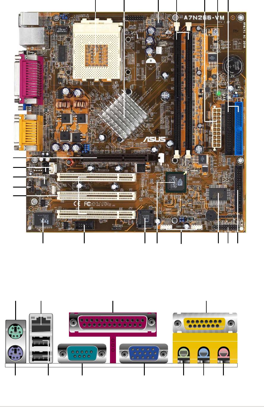
1.4.1 Component Locations
2461
3
5
7
20
19
18
17
16
11
81013 12 91415
21 23 24
22
31 30
29 28 252627
ASUS A7N266-VM motherboard user guide
5


Chapter 2
Hardware information

ASUS A7N266-VM motherboard
2.1 Motherboard installation
The A7N266-VM uses the Micro-ATX form factor, measuring 24.5 cm
(9.6 in.) x 24.5 cm (9.6 in.) - a standard fit for most large chassis.
WARNING! Unplug the power cord before installing the motherboard.
Failure to do so may cause you physical injury and damage motherboard
components.
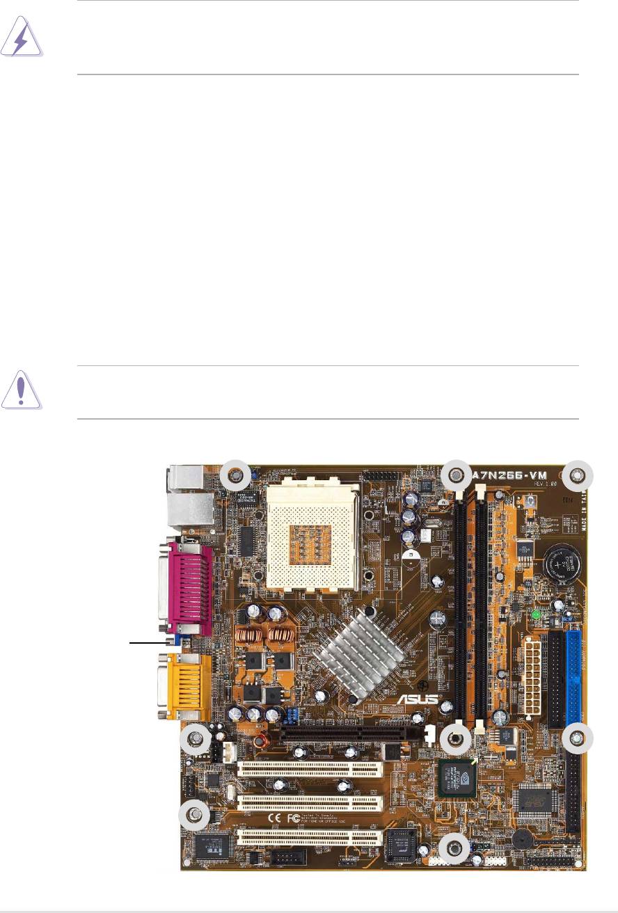
2.1.1 Placement direction
When installing the motherboard, take care to orient the chassis correctly:
The edge with external ports goes to the rear part of the chassis. Refer to the
image below. It may be more convenient to install major cables, the CPU
and modular components before fixing the motherboard inside the case frame.
2.1.2 Screw holes
Place eight (8) screws into the holes indicated by circles to secure the
motherboard to the chassis.
CAUTION! Do not overtighten the screws! Doing so may damage the
motherboard.
Place this side towards
the rear of the chassis
ASUS A7N266-VM motherboard user guide
7
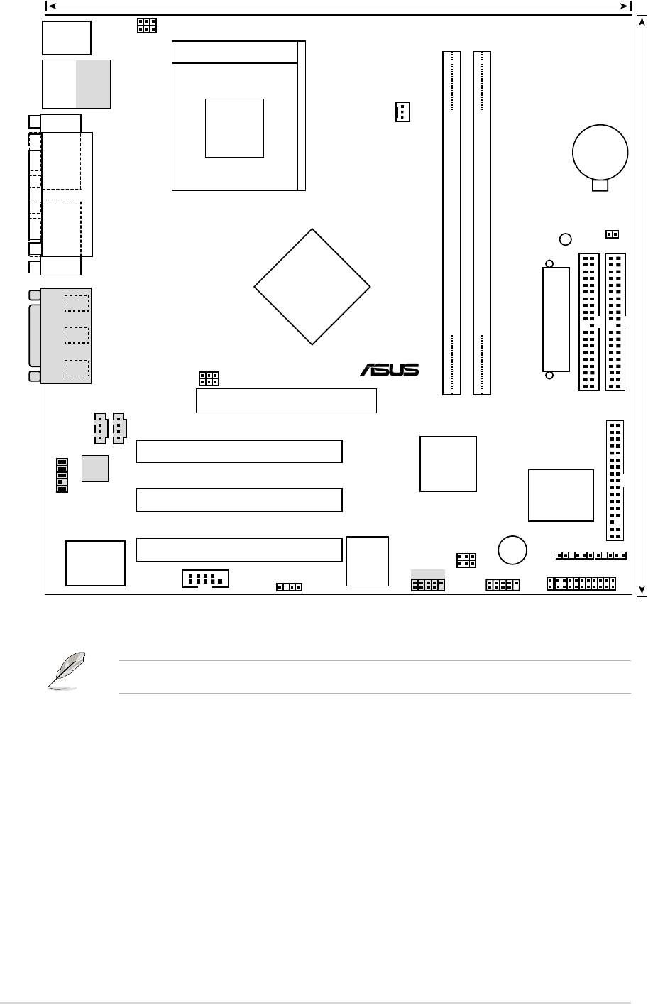
24.5cm (9.64in)
USBPWR01
A7N266-VM
PS/2
KBPWR1
T: Mouse
B: Keyboard
Socket 462
Bottom:
Top:
USB1
RJ-45
USB2
COM1
CPU_FAN
CR2032 3V
Lithium Cell
CMOS Power
PARALLEL PORT
CLRTC
PLED
Primary IDE
VGA
nVidia
220D
Line
Out
Chipset
Line
DDR DIMM1 (64/72 bit, 184-pin module)
DDR DIMM2 (64/72 bit, 184-pin module)
In
30.5cm (12.0in)
Mic
®
ATX Power Connector
GAME_AUDIO
In
BSEL0
BSEL1
0 1
2 3
Accelerated Graphics Port
CD_IN1
AUDIO_COM1
(AGP)
Secondary IDE
PCI 1
nVidia
FLOPPY
Audio
MCP-D
Codec
Chipset
ASUS
ASIC
AAPANEL1
PCI 2
with Hardware
Monitor
BUZZER
USBPWR23
USBPWR45
SMB
IR
PCI 3
Super
2Mb
I/O
BIOS
USB45
USB23
PANEL
COM2
SPDIF1
IDELED
Optional components are grayed in the above motherboard layout.
8
Chapter 2: Hardware information
