Asus A7N8X – страница 3
Инструкция к Компьютерным аксессуарам Asus A7N8X
Оглавление
- User Guide
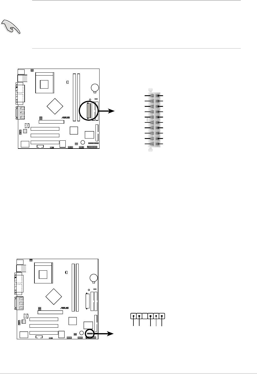
14) Power Supply Connectors (20 pin block ATXPWR)
This connector supports an ATX 12V power supply. The plug from the power
supply fits in only one orientation. Push down firmly ensuring that the pins
are aligned.
IMPORTANT! Make sure that the ATX 12V power supply offers at least
10mA on the +5-volt standby lead (+5VSB). The system may become
unstable and may experience difficulty powering up if the power supply
is inadequate. For Wake-On-LAN support, the ATX power supply must
supply at least 720mA +5VSB.
A7N266-VM
ATXPWR
+3.3VDC
+3.3VDC
-12.0VDC
+3.3VDC
COM
COM
PS_ON#
+5.0VDC
®
COM
COM
COM
+5.0VDC
COM
COM
-5.0VDC
PWR_OK
+5.0VDC
+5VSB
+5.0VDC
+12.0VDC
A7N266-VM ATX Power Connector
15) SMBus Connector (6-1 pin SMB)
This connector supports SMBus (System Management Bus) devices. SMBus
devices communicate by means of the SMBus with an SMBus host and/or
other SMBus devices. SMBus is a multi-device bus that permits multiple
chips to connect to the same bus and enable each one to act as a master by
initiating data transfer.
A7N266-VM
®
SMB
1
+3V
Ground
SMBCLK
A7N266-VM SMBus Connector
FLOATING
SMBDATA
ASUS A7N266-VM motherboard user guide
29
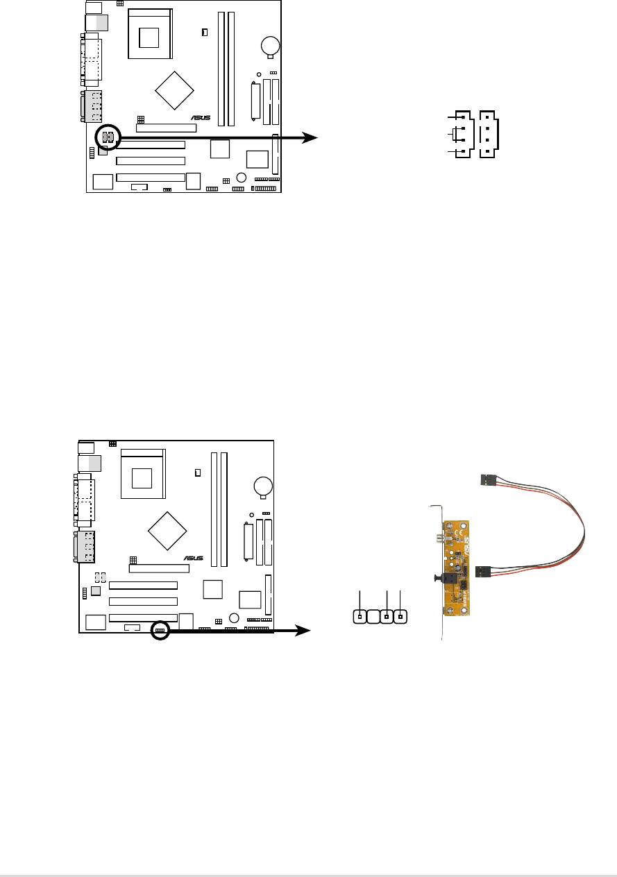
16) Internal Audio Connectors (Two x 4 pin CD_IN1, AUX) (Optional)
These connectors allow you to receive stereo audio input from sound sources
as a CD-ROM, TV tuner, or MPEG card.
A7N266-VM
CD_IN1
AUX
(Black)
(White)
®
Right Audio Channel
Ground
Left Audio Channel
A7N266-VM Internal Audio Connectors
17) Digital Audio Interfaces (4-1pin SPDIF1) (Optional)
These connectors supply an SPDIF audio cable that outputs digital audio.
A7N266-VM
SPDIF1
®
+5V
SPDIFOUT
GND
A7N266-VM Digital Audio Connector
30
Chapter 2: Hardware information
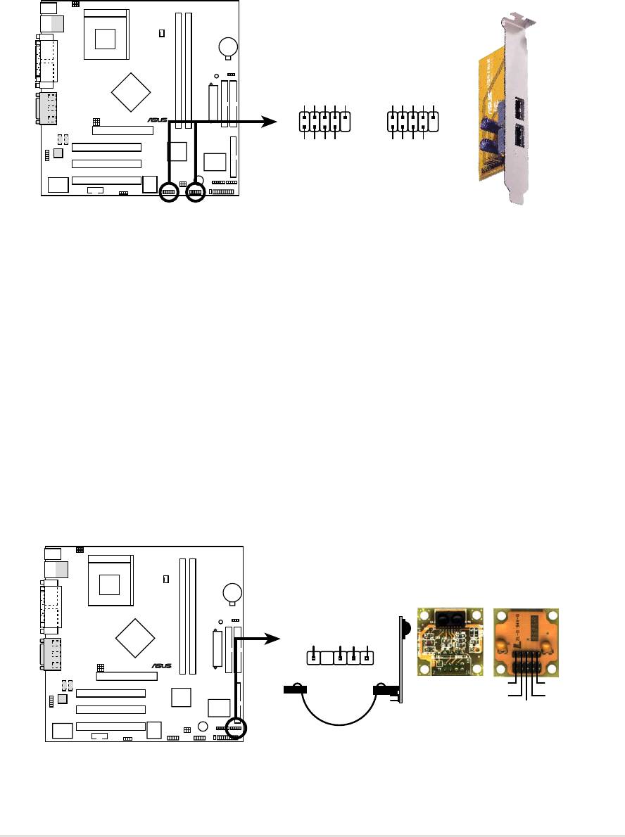
18) USB Headers (10-1 pin USB23, USB45)
If the USB port connectors on the back panel are inadequate, two USB
headers are available for four additional USB port connectors. Connect a 2-
port USB connector set to a USB header and mount the USB bracket to an
open slot in the chassis. (The USB connector set is optional and does not
come with the motherboard package.)
A7N266-VM
USB23USB45
USB Power
USBP4–
USBP4+
GND
NC
USB Power
USBP2–
USBP2+
GND
NC
15
15
®
610
610
GND
GND
USBP5–
USBP5+
USBP3–
USBP3+
USB Power
USB Power
A7N266-VM Front Panel USB Headers
19) Infrared module connector (5-1 pin IR)
This connector supports an optional wireless transmitting and receiving
infrared module. This module mounts to a small opening on system chassis
that support this feature. You must also configure the UART2 Use As
parameter in BIOS to set UART2 for use with IR. See section “4.4.2 I/O
Device Configuration” for details.
Use the five pins as shown in Back View and connect a ribbon cable from the
module to the motherboard SIR connector according to the pin definitions.
A7N266-VM
Front View Back View
IR
+5V
IRRX
GND
IRTX
®
1
IRTX
+5V
GND
(NC)
IRRX
A7N266-VM Infrared Module Connector
ASUS A7N266-VM motherboard user guide
31

The following 20-pin PANEL illustration is for items 20-26.
A7N266-VM
Keyboard Lock
Speaker
Connector
Power LED
PLED+
PLED-
Keylock
Ground
+5V
Ground
Ground
Speaker
®
PWR
GND
MLED+
MLED-
Reset
ExtSMI#
Ground
Ground
Reset SW
Message LED
ATX Power
SMI Lead
Switch*
* Requires an ATX power supply.
A7N266-VM System Panel Connectors
20) System Power LED Lead (3-1 pin PWR_LED)
This 3-1 pin connector supplies the system power LED. The LED lights up
when the system power is on, and the LED blinks when the system is in
sleep or soft-off mode.
21) Keyboard Lock Switch Lead (2 pin KEYLOCK)
This 2-pin connector supplies the case-mounted key switch for keyboard
locking.
22) System Warning Speaker Lead (4 pin SPEAKER)
This 4-pin connector supplies the case-mounted speaker to sound system
beeps and warnings.
23) System Message LED Lead (2 pin LED)
This 2-pin connector supports the system message LED to indicate receipt
of messages from a fax/modem. The normal status for this LED is ON,
when there is no incoming data signal. The LED blinks when data is received.
The system message LED feature requires an ACPI OS and driver support.
24) System Management Interrupt Lead (2 pin SMI)
This 2-pin connector permits switching to suspend mode, or “Green” mode,
in which system activity is instantly decreased to save power and to expand
the life of certain system components. Attach the case-mounted suspend
switch this 2-pin connector.
25) ATX Power Switch / Soft-Off Switch Lead (2 pin PWR)
The system power is controlled by a momentary switch attached to this
connector. Pressing the button switches the system between ON and SLEEP,
or ON and SOFT OFF, depending on the BIOS or OS settings. Pressing the
button while in the ON mode for more than 4 seconds turns the system off.
26) Reset Switch Lead (2 pin RESET)
This 2-pin connector supports the case-mounted reset switch for rebooting
the system without turning off the power switch.
32
Chapter 2: Hardware information
Chapter 3
Powering up

ASUS A7N266-VM motherboard
3.1 Starting up for the first time
1. After making all the connections, replace the system case cover.
2. Be sure that all switches are off.
3. Connect the power cord to the power connector at the back of the
system chassis.
4. Connect the power cord to a power outlet that is equipped with a surge
protector.
5. Turn on the devices in the following order:
a. Monitor
b. External SCSI devices (starting with the last device on the chain)
c. System power (if you are using an ATX power supply, you need to
switch on the power supply as well as press the ATX power switch
on the front of the chassis).
6. After applying power, the power LED on the system front panel case
lights up. For ATX power supplies, the system LED lights up when you
press the ATX power switch. If your monitor complies with “green”
standards or if it has a “power standby” feature, the monitor LED may
light up or switch between orange and green after the system LED
turns on. The system then runs the power-on tests. While the tests are
running, the BIOS beeps or additional messages appear on the
screen. If you do not see anything within 30 seconds from the time you
turned on the power, the system may have failed a power-on test.
Check the jumper settings and connections or call your retailer for
assistance.
Award BIOS Beep Codes
Beep Meaning
One short beep when No error during POST
displaying logo
Long beeps in an endless loop No DRAM installed or detected
One long beep followed by Video card not found or video card
three short beeps memory bad
High frequency beeps when CPU overheated;
system is working System running at a lower frequency
7. At power on, hold down <Delete> to enter BIOS Setup. Follow the
instructions in Chapter 4.
ASUS A7N266-VM motherboard user guide
33

3.2 Powering off the computer
You must first exit the operating system and shut down the system before
switching off the power. For ATX power supplies, you can press the ATX
power switch after exiting or shutting down the operating system. If you
use Windows 95/98/2000/XP, click the Start button, click Shut Down, then
click the OK button to shut down the computer. The power supply should
turn off after Windows shuts down.
The message “You can now safely turn off your computer” does not
appear when shutting down with ATX power supplies.
34
Chapter 3: Powering up
Chapter 4
BIOS setup

ASUS A7N266-VM motherboard
4.1 Managing and updating your BIOS
4.1.1 Using the computer system for the first time
It is recommended that you save a copy of the original motherboard BIOS
along with a Flash Memory Writer utility (AFLASH.EXE) to a bootable floppy
disk in case you need to reinstall the BIOS later. AFLASH.EXE is a Flash
Memory Writer utility that updates the BIOS by uploading a new BIOS file to
the programmable flash ROM on the motherboard. This file works only in
DOS mode. To determine the BIOS version of your motherboard, check the
last four numbers of the code displayed on the upper left-hand corner of your
screen during bootup. Larger numbers represent a newer BIOS file.
1. Type FORMAT A:/S at the DOS prompt to create a bootable system disk.
DO NOT copy AUTOEXEC.BAT and CONFIG.SYS to the disk.
2. Type COPY D:\AFLASH\AFLASH.EXE A:\ (assuming D is your CD-ROM
drive) to copy AFLASH.EXE to the boot disk you created.
NOTE! AFLASH works only in DOS mode. It does not work in the DOS
prompt within Windows, and does not work with certain memory drivers
that may be loaded when you boot from the hard drive. It is recommended
that you reboot using a floppy disk.
3. Reboot the computer from the floppy disk.
NOTE! BIOS setup must specify “Floppy” as the first item in the boot
sequence.
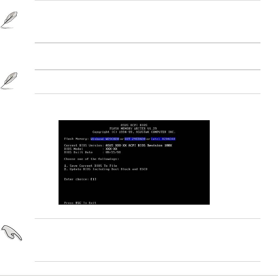
4. In DOS mode, type A:\AFLASH <Enter> to run AFLASH.
IMPORTANT! If the word “unknown” appears after Flash Memory:, the
memory chip is either not programmable or is not supported by the ACPI
BIOS and therefore, cannot be programmed by the Flash Memory Writer
utility.
ASUS A7N266-VM motherboard user guide
35
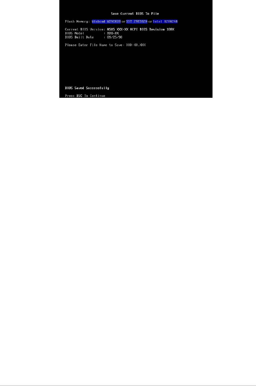
5. Select 1. Save Current BIOS to File from the Main menu and press
<Enter>. The Save Current BIOS To File screen appears.
6. Type a filename and the path, for example, A:\XXX-XX.XXX, then
press <Enter>.
36
Chapter 4: BIOS Setup
4.1.2 Updating BIOS procedures
CAUTION! Update the BIOS only if you have problems with the
motherboard and you are sure that the new BIOS revision will solve your
problems. Careless updating may result to more problems with the
motherboard!
1. FTP) (see ASUS CONTACT INFORMATION on page x for details) and
save to the boot floppy disk you created earlier.
2. Boot from the floppy disk.
3. At the “A:\” prompt, type AFLASH and then press <Enter>.
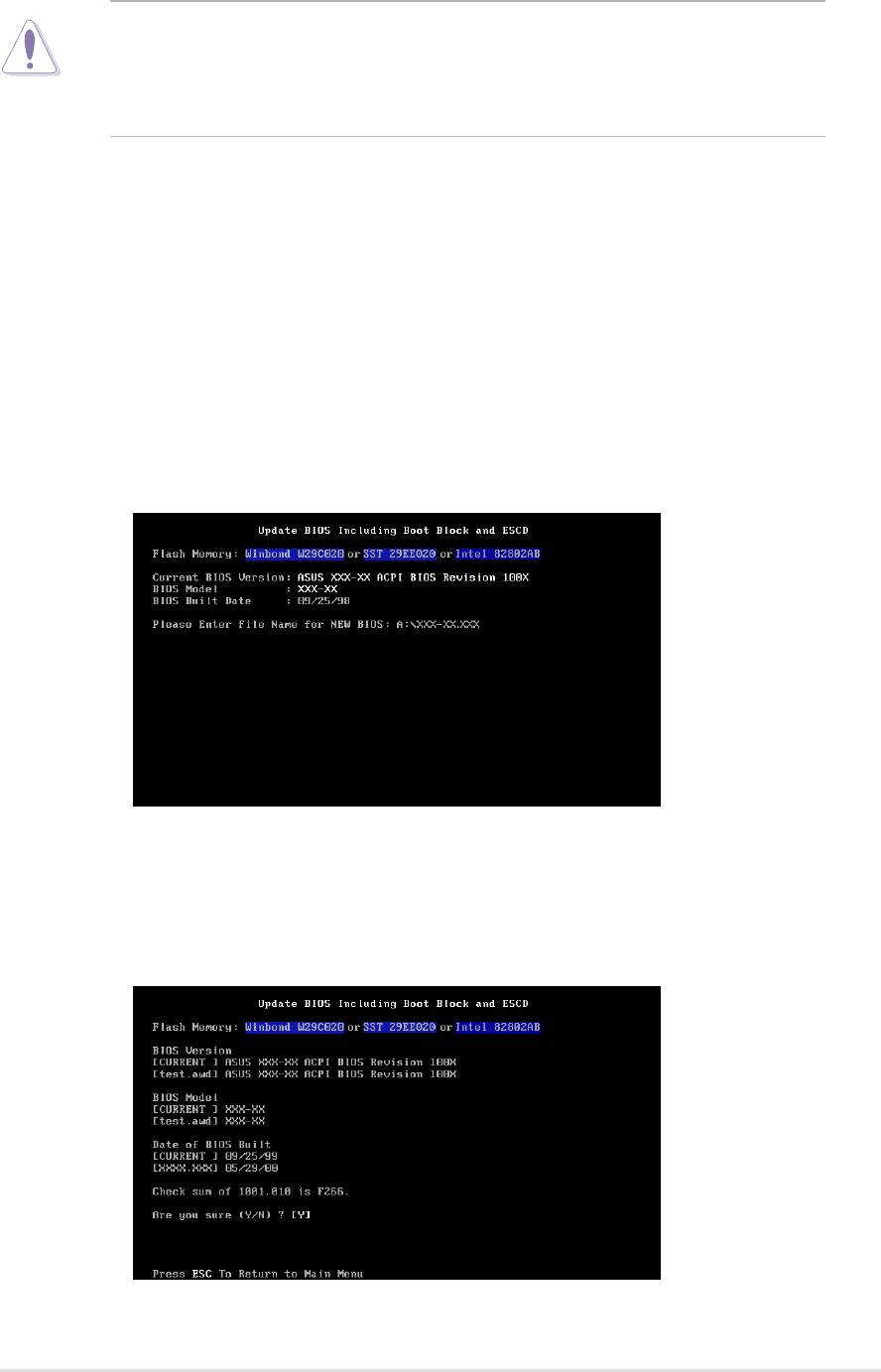
4. At the Main Menu, type 2 then press <Enter>. The Update BIOS Including
Boot Block and ESCD screen appears.
5. Type the filename of your new BIOS and the path, for example, A:\XXX-
XX.XXX, then press <Enter>.
To cancel this operation, press <Enter>.
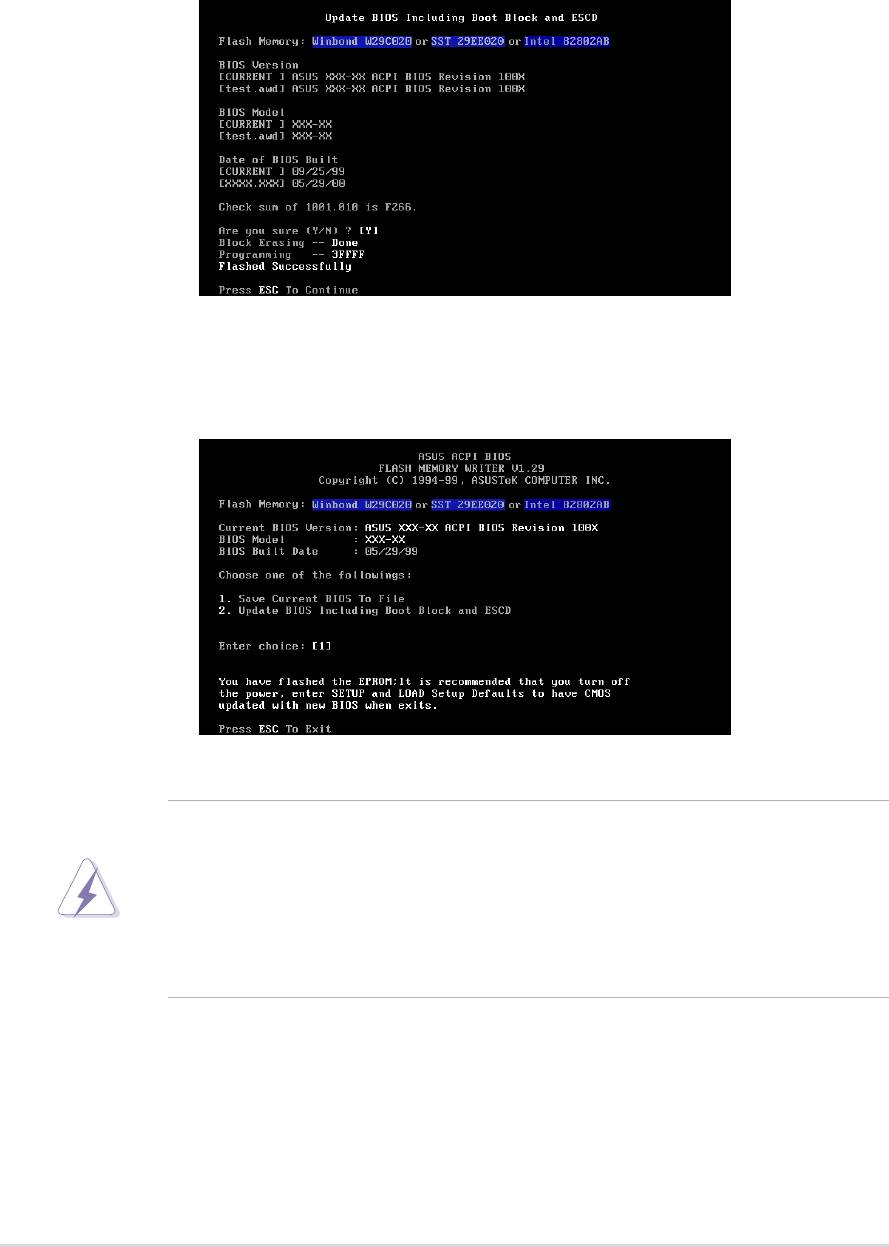
6. When prompted to confirm the BIOS update, press Y to start the
update.
ASUS A7N266-VM motherboard user guide
37
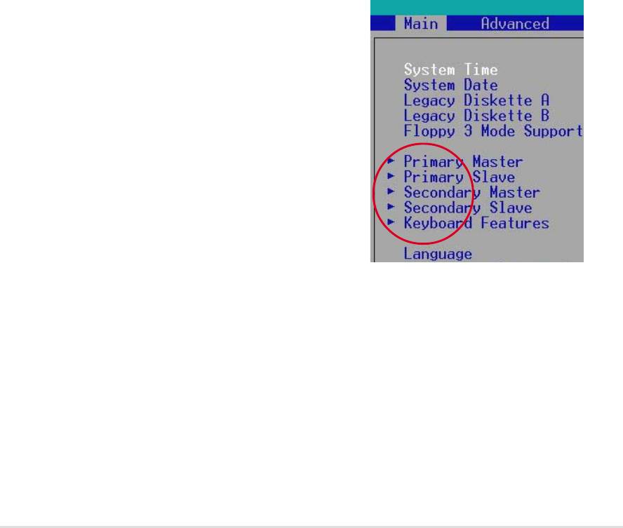
7. The utility starts to program the new BIOS information into the Flash
ROM. The boot block is updated automatically only when necessary.
This minimizes the possibility of boot problems in case of update failures.
When the programming is done, the message “Flashed Successfully”
appears.
8. Follow the onscreen instructions to continue.
WARNING! If you encounter problems while updating the new BIOS,
DO NOT turn off the system because this may cause boot problems.
Just repeat the process, and if the problem persists, load the original
BIOS file you saved to the boot disk. If the Flash Memory Writer utility is
not able to successfully update a complete BIOS file, the system may not
boot. If this happens, call the ASUS service center for support.
38
Chapter 4: BIOS Setup

4.2 BIOS Setup program
This motherboard supports a programmable EEPROM that you can update
using the provided utility described in section “4.1 Managing and updating
your BIOS.”
Use the BIOS Setup program when you are installing a motherboard,
reconfiguring your system, or prompted to “Run Setup”. This section explains
how to configure your system using this utility.
Even if you are not prompted to use the Setup program, you may want to
change the configuration of your computer in the future. For example, you
may want to enable the security password feature or make changes to the
power management settings. This requires you to reconfigure your system
using the BIOS Setup program so that the computer can recognize these
changes and record them in the CMOS RAM of the EEPROM.
The EEPROM on the motherboard stores the Setup utility. When you start
up the computer, the system provides you with the opportunity to run this
program. Press <Delete> during the Power-On Self Test (POST) to enter the
Setup utility, otherwise, POST continues with its test routines.
If you wish to enter Setup after POST, restart the system by pressing <Ctrl>
+ <Alt> + <Delete>, or by pressing the reset button on the system chassis.
You can also restart by turning the system off and then back on. Do this last
option only if the first two failed.
The Setup program is designed to make it as easy to use as possible. It is a
menu-driven program, which means you can scroll through the various sub-
menus and make your selections among the predetermined choices.
NOTE! Because the BIOS software is constantly being updated, the
following BIOS setup screens and descriptions are for reference purposes
only, and may not exactly match what you see on your screen.
ASUS A7N266-VM motherboard user guide
39

4.2.1 BIOS menu bar
The top of the screen has a menu bar with the following selections:
MAIN Use this menu to make changes to the basic system
configuration.
ADVANCED Use this menu to enable and make changes to the
advanced features.
POWER Use this menu to configure and enable Power Management
features.
BOOT Use this menu to configure the default system device used
to locate and load the Operating System.
EXIT Use this menu to exit the current menu or to exit the Setup
program.
To access the menu bar items, press the right or left arrow key on the keyboard
until the desired item is highlighted.
4.2.2 Legend bar
At the bottom of the Setup screen is a legend bar. The keys in the legend bar
allow you to navigate through the various setup menus. The following table
lists the keys found in the legend bar with their corresponding functions.
Navigation Key(s) Function Description
<F1> or <Alt + H> Displays the General Help screen from any-
where in the BIOS Setup
<Esc> Jumps to the Exit menu or returns to the main
menu from a sub-menu
Left or Right arrow Selects the menu item to the left or right
Up or Down arrow Moves the highlight up or down between fields
- (minus key) Scrolls backward through the values for the
highlighted field
+ (plus key) or spacebar Scrolls forward through the values for the high-
lighted field
<Enter> Brings up a selection menu for the highlighted
field
<Home> or <PgUp> Moves the cursor to the first field
<End> or <PgDn> Moves the cursor to the last field
<F5> Resets the current screen to its Setup Defaults
<F10> Saves changes and exits Setup
40
Chapter 4: BIOS Setup
General help
In addition to the Item Specific Help window, the BIOS setup program also
provides a General Help screen. You may launch this screen from any menu
by simply pressing <F1> or the <Alt> + <H> combination. The General Help
screen lists the legend keys and their corresponding functions.
Saving changes and exiting the Setup program
See “4.7 Exit Menu” for detailed information on saving changes and exiting
the setup program.
Scroll bar
When a scroll bar appears to the right of a help window, it indicates that
there is more information to be displayed that will not fit in the window. Use
<PgUp> and <PgDn> or the up and down arrow keys to scroll through the
entire help document. Press <Home> to display the first page, press <End>
to go to the last page. To exit the help window, press <Enter> or <Esc>.
Sub-menu
Note that a right pointer symbol (as shown on
the left) appears to the left of certain fields. This
pointer indicates that you can display a sub-
menu from this field. A sub-menu contains
additional options for a field parameter. To
display a sub-menu, move the highlight to the
field and press <Enter>. The sub-menu appears.
Use the legend keys to enter values and move
from field to field within a sub-menu as you would
within a menu. Use the <Esc> key to return to
the main menu. Take some time to familiarize
yourself with the legend keys and their
corresponding functions. Practice navigating through the various menus and
sub-menus. If you accidentally make unwanted changes to any of the fields,
use the set default hot key <F5> to load the Setup default values. While
moving around through the Setup program, note that explanations appear in
the Item Specific Help window located to the right of each menu. This window
displays the help text for the currently highlighted field.
ASUS A7N266-VM motherboard user guide
41
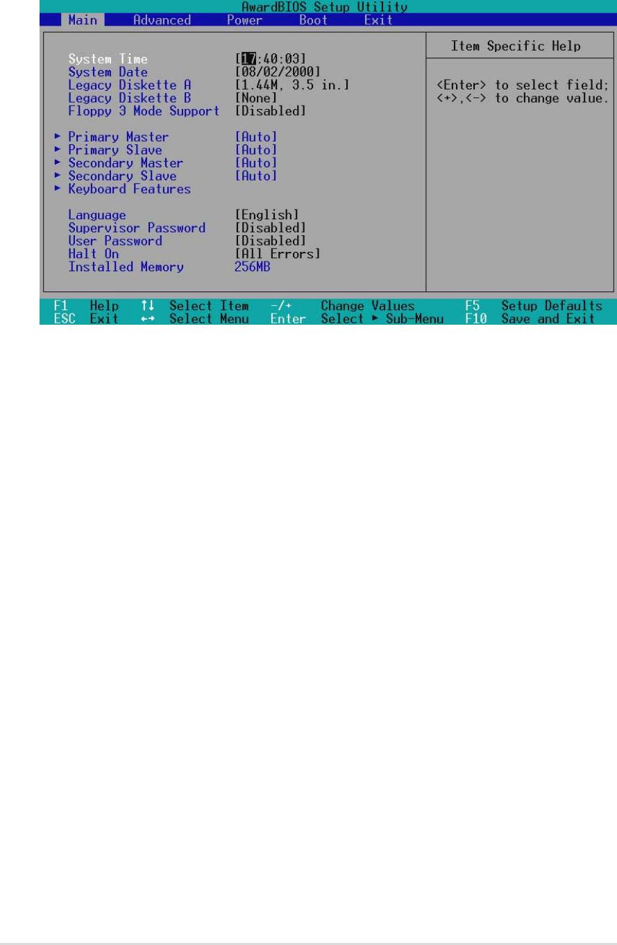
4.3 Main Menu
When you enter the Setup program, the following screen appears.
System Time [XX:XX:XX]
Sets the system to the time that you specify (usually the current time). The
format is hour, minute, second. Valid values for hour, minute and second are
Hour: (00 to 23), Minute: (00 to 59), Second: (00 to 59). Use the <Tab> or
<Shift> + <Tab> keys to move between the hour, minute, and second fields.
System Date [XX/XX/XXXX]
Sets the system to the date that you specify (usually the current date). The
format is month, day, year. Valid values for month, day, and year are Month:
(1 to 12), Day: (1 to 31), Year: (up to 2084). Use the <Tab> or <Shift> +
<Tab> keys to move between the month, day, and year fields.
Legacy Diskette A [1.44M, 3.5 in.]
Sets the type of floppy drive installed. Configuration options: [None] [360K,
5.25 in.] [1.2M , 5.25 in.] [720K , 3.5 in.] [1.44M, 3.5 in.] [2.88M, 3.5 in.]
Floppy 3 Mode Support [Disabled]
This is required to support older Japanese floppy drives. The Floppy 3 Mode
feature allows reading and writing of 1.2MB (as opposed to 1.44MB) on a
3.5-inch diskette. Configuration options: [Disabled] [Enabled]
42
Chapter 4: BIOS Setup
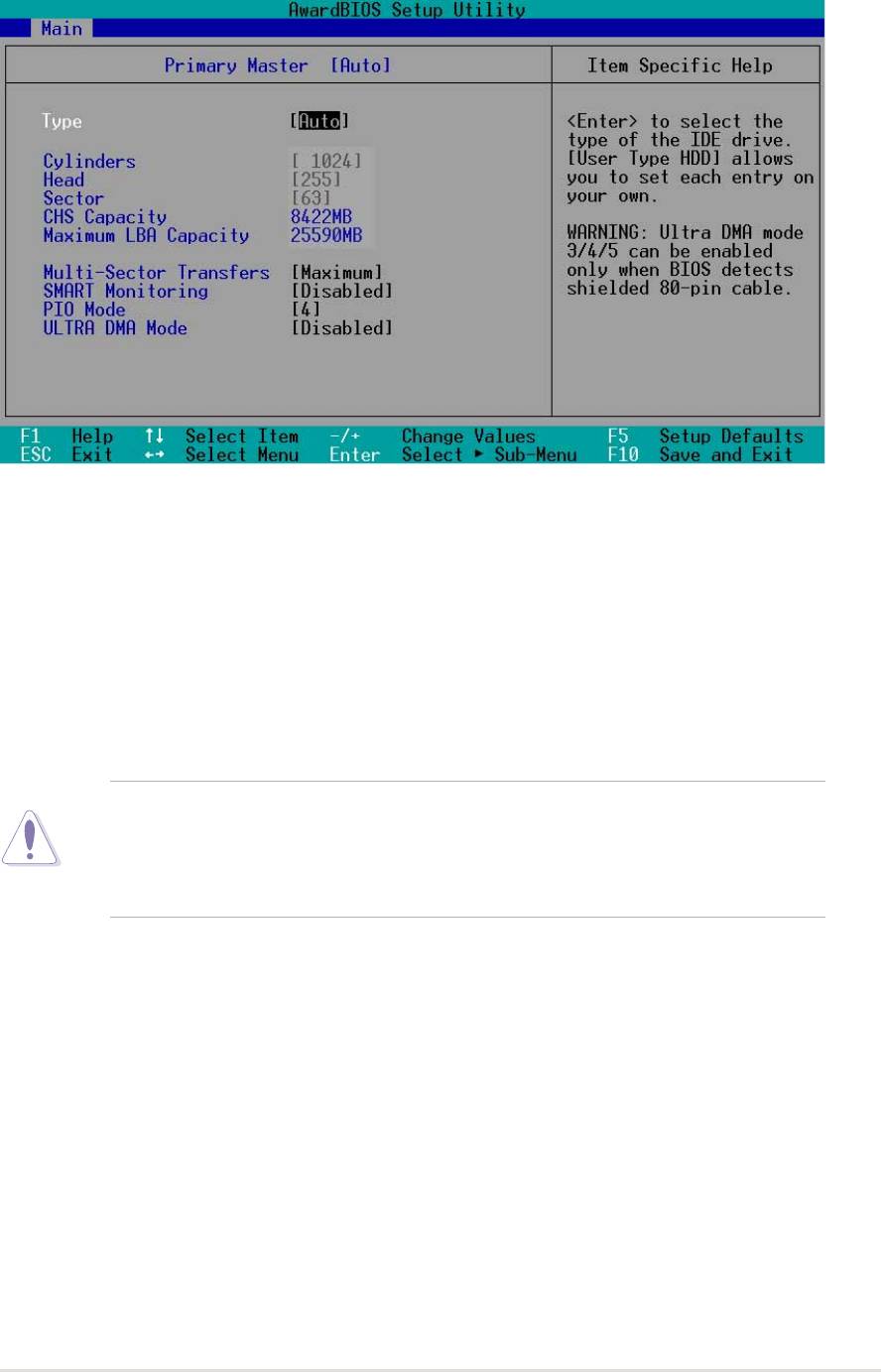
4.3.1 Primary and Secondary Master/Slave
Type [Auto]
Select [Auto] to automatically detect an IDE hard disk drive. If automatic
detection is successful, Setup automatically fills in the correct values for the
remaining fields on this sub-menu. If automatic detection fails, this may be
because the hard disk drive is too old or too new. If the hard disk was already
formatted on an older system, Setup may detect incorrect parameters. In
these cases, select [User Type HDD] to manually enter the IDE hard disk
drive parameters. Refer to the next section for details.
CAUTION! Before attempting to configure a hard disk drive, make sure
you have the correct configuration information supplied by the drive
manufacturer. Incorrect settings may cause the system to fail to recognize
the installed hard disk.
ASUS A7N266-VM motherboard user guide
43
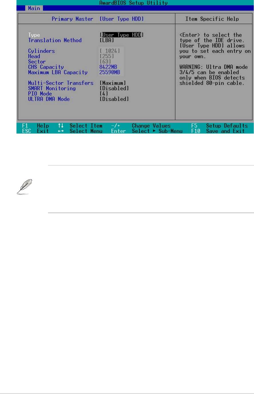
[User Type HDD]
Manually enter the number of cylinders, heads and sectors per track for the
drive. Refer to the drive documentation or on the drive label for this information.
NOTE! After entering the IDE hard disk drive information into BIOS, use
a disk utility, such as FDISK, to partition and format new IDE hard disk
drives. This is necessary so that you can write or read data from the hard
disk. Make sure to set the partition of the Primary IDE hard disk drives to
active.
If no drive is installed or if you are removing a drive and not replacing it,
select [None].
Other options for the Type field are:
[CD-ROM] - for IDE CD-ROM drives
[LS-120] - for LS-120 compatible floppy disk drives
[ZIP] - for ZIP-compatible disk drives
[MO] - for IDE magneto optical disk drives
[Other ATAPI Device] - for IDE devices not listed here
After making your selections on this sub-menu, press the <Esc> key to return
to the Main menu. When the Main menu appears, the hard disk drive field
displays the size for the hard disk drive that you configured.
44
Chapter 4: BIOS Setup
