Asus P3-P5G31: инструкция
Раздел: Компьютерная техника, комплектующие, аксессуары
Тип: Мультимедийный Компьютер
Инструкция к Мультимедийному Компьютеру Asus P3-P5G31
English
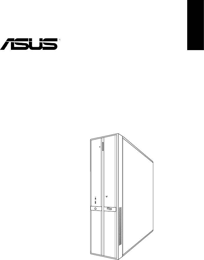
P3-Series
ASUS PC (Desktop Barebone)
Installation manual
'
9;
9
(
G
X
K
H
UT
K
Download the latest manual from the ASUS website: www.asus.com
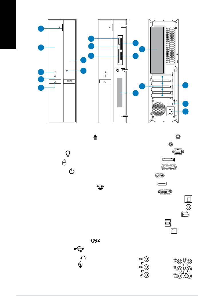
Front/Rear panel features
Front (Close)
Front (Open)
Rear
English
15
16
1. Optical drive eject button ( )
2. Optical drive bay cover
3. Power LED (
)
4. HDD LED (
)
5. Power button ( )
6. Front panel cover
7. Open the front panel cover (
)
®
8. Memory Stick
/Pro™card slot (MS)
9. Card reader LED (
R/W)
®
10. CompactFlash
card slot (CF)
®
11. SmartMedia
card slot (SM)
12. Secure Digital™/MultimediaCard
slot (SD/MMC)
13.* • 4-pin IEEE 1394a port (
)
• USB 2.0 ports (
)
• Headphones jack (
)
• Microphone jack (
)
2 Installation manual
'9;9(GXKHUTK
1
8
11
9
2
14
10
12
6
7
3
4
5
13
39
93
8=
9*33)
),
17
18
14.* • PS/2 keyboard port ( )
• PS/2 mouse port (
)
• Serial (COM) port (
)
• E-SATA port (
)
• Parallel port (
)
• VGA port (
)
• HDMI port (
)
• DVI-D port (
)
• Optical S/PDIF Out port (
)
• Coaxial S/PDIF Out port (
)
• 6-pin IEEE 1394a port (
)
• USB 2.0 ports (
)
• LAN (RJ-45) port (
)
• One of the following audio
jacks congurations:
• 6-channel • 8-channel
15. Expansion slot metal brackets
17.** Voltage selector switch
16. Metal bracket lock
18. Power connector
NOTE: *The front/rear panel ports and their locations may vary, depending on the
English
model of your system. For detailed descriptions, refer to the system User Guide.
NOTE: **The system’s power supply unit has a 115V / 230V voltage selector switch
located beside the power connector. Use this switch to select the appropriate system
input voltage according to the voltage supply in your area.
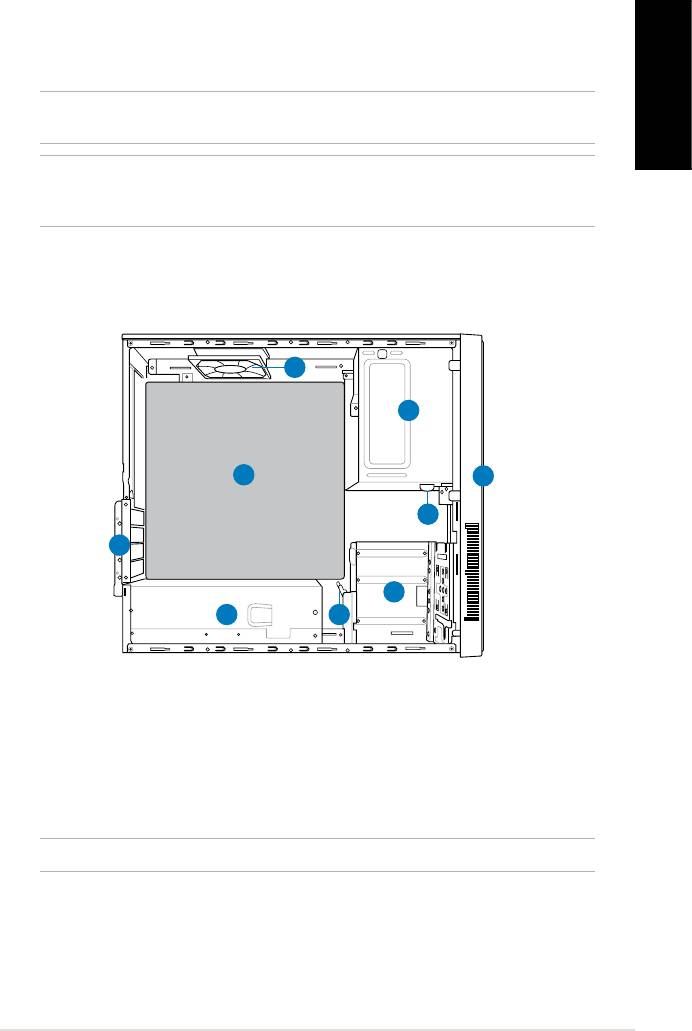
Internal components
9
1
8
2
3
7
4
6
5
1. 5.25-inch optical drive bay
6. Power supply unit
2. Front panel cover
7. Metal bracket lock
3. Optical drive lock
8.* ASUS motherboard
4. 3.5-inch hard disk drive bays
9. Chassis fan
5. Hard disk drive lock
NOTE: *Refer to the system User Guide for motherboard details.
3Installation manual
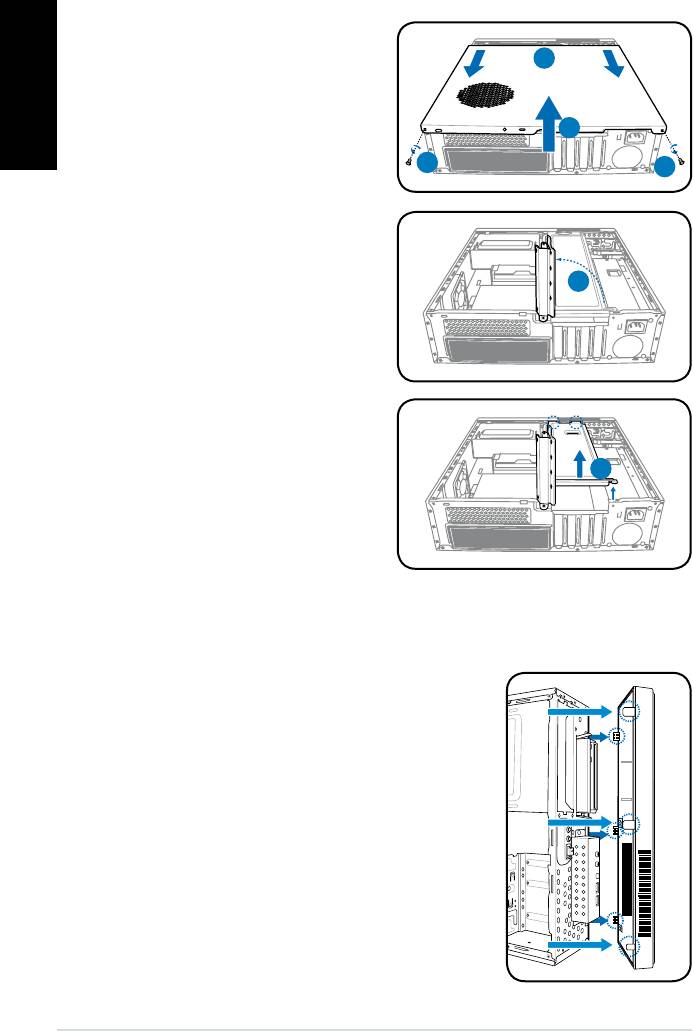
Removing the cover
1. Remove the cover screws on the
English
rear panel. Keep the screws for
2
later use.
2. Pull the cover toward the rear
panel.
3
3. Lift the cover and set it aside.
1
1
4. Lift the expansion card lock to a
90º-100º angle.
4
5. Lift the chassis support bracket
and remove it.
5
Removing the front panel cover
1. Locate the front panel cover tabs on the right
side of the chassis and the cover hooks on
the left. Lift them until they disengage from the
chassis.
2. Remove the front panel cover, and set it aside.
4 Installation manual
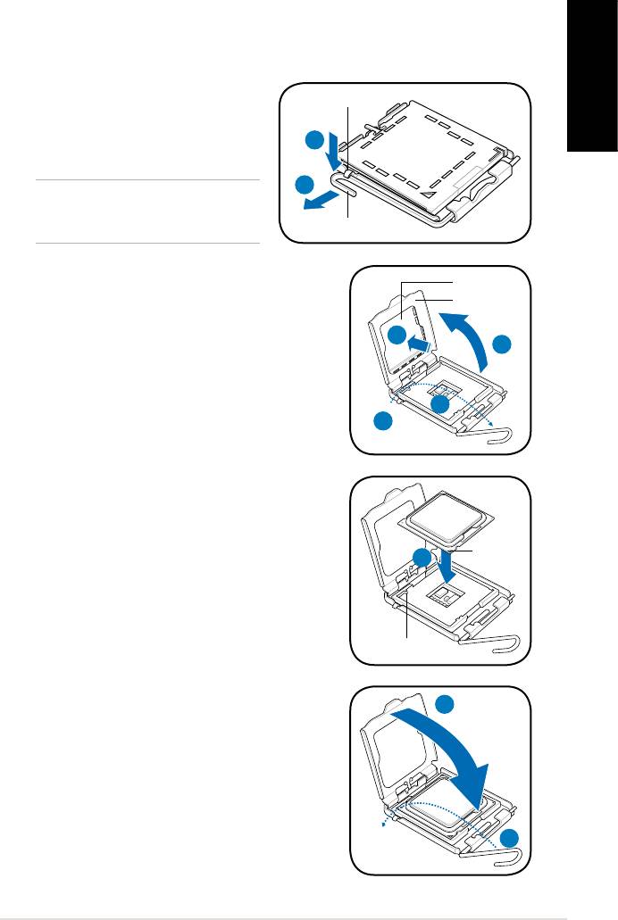
Installing a CPU
®
Installing an Intel
CPU in the LGA775 package
1. Locate the CPU socket on the motherboard.
2. Press the load lever with your
Retention tab
English
thumb (2A), and then move it to the
left (2B) until it is released from the
2A
retention tab.
2B
CAUTION: To prevent damage to the
socket pins, do not remove the PnP
cap unless you are installing a CPU.
Load lever
3. Lift the load lever in the direction of the arrow to
PnP cap
a 135º angle.
Load plate
4. Lift the load plate with your thumb and
forenger to a 100º angle (4A), then push the
4B
4A
PnP cap from the load plate window to remove
(4B).
3
3
5. Position the CPU over the socket, making
sure that the gold triangle is on the bottom-left
corner of the socket. Fit the socket alignment
key into the CPU notch.
Gold
5
triangle
mark
Alignment key
6. Close the load plate (6A), and then push the
6A
load lever (6B) until it snaps into the retention
tab.
6B
5Installation manual
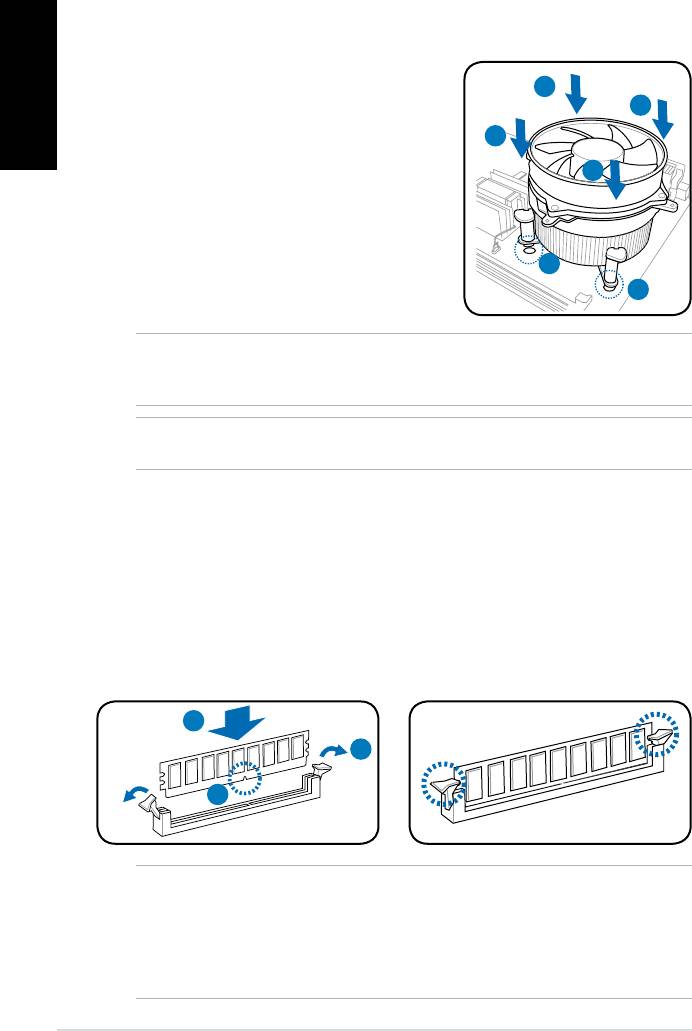
Installing the CPU fan and heatsink assembly
®
Installing an Intel
CPU heatsink and fan
English
1. Place the heatsink on top of the installed
CPU, making sure that the four fasteners
A
B
match the holes on the motherboard.
2. Push down two fasteners at a time in a
B
diagonal sequence to secure the heatsink
A
and fan assembly in place.
3. When the fan and heatsink assembly is in
place, connect the CPU fan cable to the
connector on the motherboard.
1
1
NOTE: Your boxed CPU should come with installation instructions for the CPU and fan/
heatsink assembly. If the instructions in this section do not match the CPU documentation,
follow the latter.
CAUTION: Do not forget to connect the CPU fan connector! Hardware monitoring error
can occur if you fail to plug this connector.
Installing a DIMM
1. Locate the DIMM sockets in the motherboard.
2. Unlock a DIMM socket by pressing the retaining clips outward.
3. Align a DIMM on the socket such that the notch on the DIMM matches the
break on the socket.
4. Push the DIMM to the socket until the retaining clips snap inward.
4
2
3
CAUTION:
• Unplug the power supply before adding or removing DIMMs. Failure to do so may
cause damage to the motherboard and/or components.
• A DIMM is keyed with a notch so that it ts in only one direction. Do not force
a DIMM into a socket to avoid damaging the DIMM.
6 Installation manual
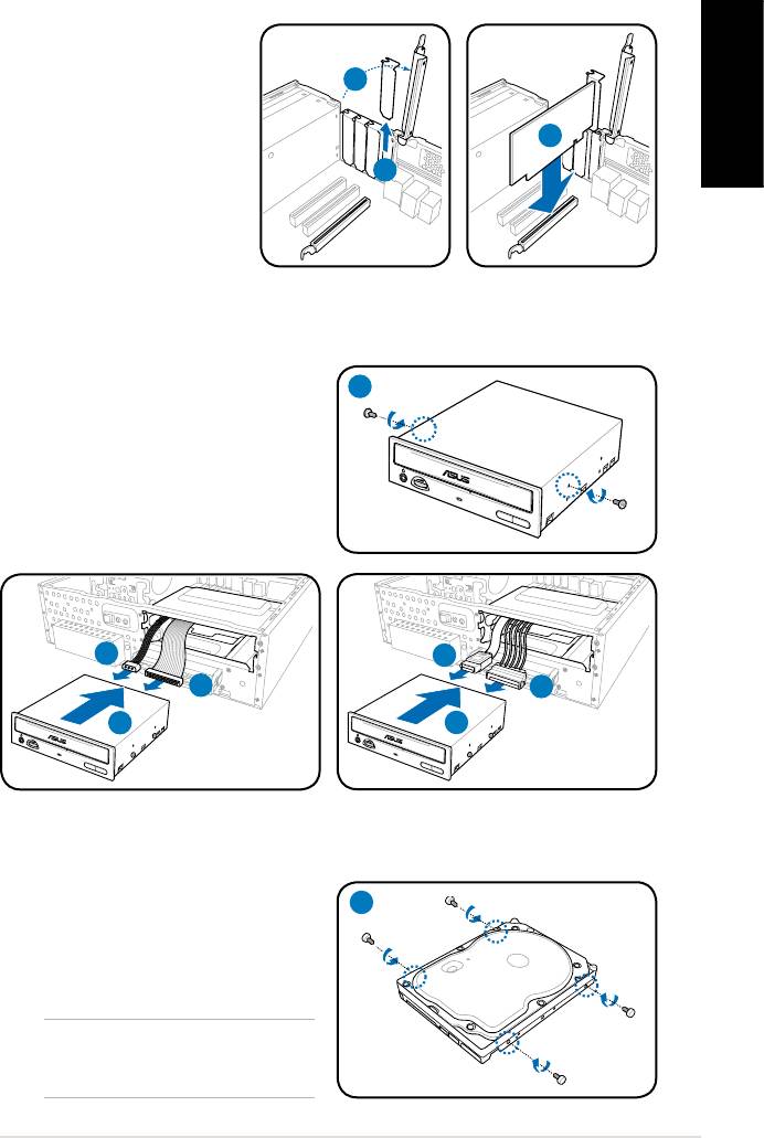
Installing an expansion card
1. Lift the expansion card
lock to a 90º-100º angle.
1
2. Remove the metal cover
opposite the slot that you
English
intend to use.
3
3. Insert the card connector
2
to the slot, and press the
card rmly until it ts in
place.
Installing an optical drive
1. Drive a screw to the screw hole on
1
both sides of the optical drive.
2. Connect the IDE/SATA signal plug
(2A) and IDE/SATA power plug (2B)
to the connectors at the back of the
IDE/SATA optical drive.
3. Push the drive all the way into the
bay until the drive lock clicks.
2B
2A
2A
2B
3
3
IDE
SATA
Installing a SATA hard disk drive
1. Drive two screws with rubber
1
washers on both sides of the hard
disk drive.
NOTE: Before using the hard disk
drive screws, put the supplied rubber
washers onto the screws.
7Installation manual
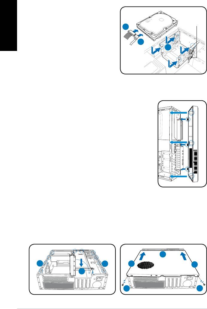
2. Connect the SATA signal plug
English
(2A) and power plug (2B) to the
connectors at the back of the hard
HDD drive lock
2B
disk drive.
3. Place the HDD into the bay. Make
2A
sure the HDD screws align with the
3
screw tracks.
4. Push the drive to the direction
of the arrows until the drive lock
clicks.
Reinstalling the front panel cover
1. Insert the front panel cover tabs to the holes on the
right side of the chassis.
2. Insert the front panel cover hooks to the chassis
until the cover ts in place.
Reinstalling the cover
1. Reinstall the chassis support bracket and the expansion card lock.
2. Insert the cover tabs to the holes on both sides of the chassis.
3. Push the cover toward the front panel until it ts in place.
4. Secure the cover with two screws you removed earlier.
3
2
2
2
2
1
4
4
8 Installation manual


