Asus M3N78-EMH HDMI: инструкция
Раздел: Компьютерная техника, комплектующие, аксессуары
Тип: Материнская Плата
Инструкция к Материнской Плате Asus M3N78-EMH HDMI

M3N78-EMH HDMI
Motherboard

E3715
Second Edition V2
April 2008
Copyright © 2008 ASUSTeK COMPUTER INC. All Rights Reserved.
No part of this manual, including the products and software described in it, may be reproduced,
transmitted, transcribed, stored in a retrieval system, or translated into any language in any form or by any
means, except documentation kept by the purchaser for backup purposes, without the express written
permission of ASUSTeK COMPUTER INC. (“ASUS”).
Product warranty or service will not be extended if: (1) the product is repaired, modied or altered, unless
such repair, modication of alteration is authorized in writing by ASUS; or (2) the serial number of the
product is defaced or missing.
ASUS PROVIDES THIS MANUAL “AS IS” WITHOUT WARRANTY OF ANY KIND, EITHER EXPRESS
OR IMPLIED, INCLUDING BUT NOT LIMITED TO THE IMPLIED WARRANTIES OR CONDITIONS OF
MERCHANTABILITY OR FITNESS FOR A PARTICULAR PURPOSE. IN NO EVENT SHALL ASUS, ITS
DIRECTORS, OFFICERS, EMPLOYEES OR AGENTS BE LIABLE FOR ANY INDIRECT, SPECIAL,
INCIDENTAL, OR CONSEQUENTIAL DAMAGES (INCLUDING DAMAGES FOR LOSS OF PROFITS,
LOSS OF BUSINESS, LOSS OF USE OR DATA, INTERRUPTION OF BUSINESS AND THE LIKE),
EVEN IF ASUS HAS BEEN ADVISED OF THE POSSIBILITY OF SUCH DAMAGES ARISING FROM ANY
DEFECT OR ERROR IN THIS MANUAL OR PRODUCT.
SPECIFICATIONS AND INFORMATION CONTAINED IN THIS MANUAL ARE FURNISHED FOR
INFORMATIONAL USE ONLY, AND ARE SUBJECT TO CHANGE AT ANY TIME WITHOUT NOTICE,
AND SHOULD NOT BE CONSTRUED AS A COMMITMENT BY ASUS. ASUS ASSUMES NO
RESPONSIBILITY OR LIABILITY FOR ANY ERRORS OR INACCURACIES THAT MAY APPEAR IN THIS
MANUAL, INCLUDING THE PRODUCTS AND SOFTWARE DESCRIBED IN IT.
Products and corporate names appearing in this manual may or may not be registered trademarks or
copyrights of their respective companies, and are used only for identication or explanation and to the
owners’ benet, without intent to infringe.
ii

Contents
Notices ......................................................................................................... vi
Safety information ..................................................................................... vii
About this guide ....................................................................................... viii
M3N78-EMH HDMI specications summary .............................................. x
Chapter 1: Product introduction
1.1 Welcome! ..................................................................................... 1-2
1.2 Package contents .........................................................................
1-2
1.3 Special features ............................................................................
1-2
1.3.1 Product highlights ...........................................................
1-2
1.3.2 Innovative ASUS features ..............................................
1-5
1.4 Before you proceed .....................................................................
1-6
1.5 Motherboard overview .................................................................
1-7
1.5.1 Motherboard layout .........................................................
1-7
1.5.2 Placement direction ........................................................
1-8
1.5.3 Screw holes ....................................................................
1-8
1.6 Central Processing Unit (CPU) ...................................................
1-9
1.6.1 Installing the CPU ...........................................................
1-9
1.6.2 Installing the heatsink and fan .......................................
1-11
1.7 System memory .........................................................................
1-13
1.7.1 Overview .......................................................................
1-13
1.7.2 Memory congurations ..................................................
1-13
1.7.3 Installing a DIMM ..........................................................
1-17
1.7.4 Removing a DIMM ........................................................
1-17
1.8 Expansion slots ..........................................................................
1-18
1.8.1 Installing an expansion card .........................................
1-18
1.8.2 Conguring an expansion card .....................................
1-18
1.8.3 PCI slots ........................................................................
1-21
1.8.4 PCI Express x1 slot .......................................................
1-21
1.8.5 PCI Express x16 slot .....................................................
1-21
1.9 Jumpers ......................................................................................
1-22
1.10 Connectors .................................................................................
1-25
1.10.1 Rear panel connectors ..................................................
1-25
1.10.2 Internal connectors .......................................................
1-27
iii

Contents
Chapter 2: BIOS setup
2.1 Managing and updating your BIOS ............................................ 2-2
2.1.1 Creating a bootable oppy disk .......................................
2-2
2.1.2 ASUS EZ Flash 2 utility ...................................................
2-4
2.1.3 AFUDOS utility ................................................................
2-5
2.1.4 ASUS CrashFree BIOS 3 utility ......................................
2-7
2.1.5 ASUS Update utility ........................................................
2-9
2.2 BIOS setup program ..................................................................
2-12
2.2.1 BIOS menu screen ........................................................
2-13
2.2.2 Menu bar .......................................................................
2-13
2.2.3 Navigation keys .............................................................
2-14
2.2.4 Menu items ...................................................................
2-14
2.2.5 Sub-menu items ............................................................
2-14
2.2.6 Conguration elds .......................................................
2-14
2.2.7 Pop-up window .............................................................
2-14
2.2.8 Scroll bar .......................................................................
2-14
2.2.9 General help .................................................................
2-14
2.3 Main menu ..................................................................................
2-15
2.3.1 System Time .................................................................
2-15
2.3.2 System Date .................................................................
2-15
2.3.3 Legacy Diskette A ........................................................
2-15
2.3.4 Primary IDE Master/Slave, SATA1~4 ............................
2-16
2.3.5 IDE Conguration ..........................................................
2-18
2.3.6 System Information .......................................................
2-19
2.4 Advanced menu .........................................................................
2-20
2.4.1 JumperFree Conguration ............................................
2-20
2.4.2 CPU Conguration ........................................................
2-22
2.4.3 Chipset ..........................................................................
2-23
2.4.4 Onboard Devices Conguration ....................................
2-27
2.4.5 PCI PnP ........................................................................
2-28
2.4.6 USB Conguration ........................................................
2-29
2.5 Power menu ................................................................................
2-30
2.5.1 Suspend Mode ..............................................................
2-30
2.5.2 ACPI
2.0 Support ......................................................... 2-30
2.5.3 ACPI APIC Support .......................................................
2-30
iv

Contents
2.5.4 APM Conguration ........................................................ 2-31
2.5.5 Hardware Monitor .........................................................
2-32
2.6 Boot menu ..................................................................................
2-33
2.6.1 Boot Device Priority ......................................................
2-33
2.6.2 Boot Settings Conguration ..........................................
2-34
2.6.3 Security .........................................................................
2-35
2.7 Tools menu .................................................................................
2-37
ASUS EZ Flash 2 ......................................................................... 2-37
2.8 Exit menu ....................................................................................
2-38
Chapter 3: Software support
3.1 Installing an operating system ................................................... 3-2
3.2 Support DVD information ............................................................
3-2
3.2.1 Running the support DVD ...............................................
3-2
3.2.2 Drivers menu ...................................................................
3-3
3.2.3 Utilities menu ..................................................................
3-4
3.2.4 Make Disk menu .............................................................
3-6
3.2.5 Manual menu ..................................................................
3-8
3.2.6 ASUS Contact information ..............................................
3-8
3.2.7 Other information ............................................................
3-9
3.3 Creating a RAID driver disk .......................................................
3-11
3.3.1 Creating a RAID driver disk without entering the OS .....
3-11
®
3.3.2 Creating a RAID driver disk in Windows
.......................3-11
®
Chapter 4: NVIDIA
technology support
®
®
4.1 NVIDIA
Hybrid SLI
Technology ............................................... 4-2
4.1.1 System requirements .....................................................
4-2
4.1.2
Enabling Hybrid SLI ........................................................ 4-3
v

Notices
Federal Communications Commission Statement
This device complies with Part 15 of the FCC Rules. Operation is subject to the
following two conditions:
•
This device may not cause harmful interference, and
•
This device must accept any interference received including interference that
may cause undesired operation.
This equipment has been tested and found to comply with the limits for a
Class B digital device, pursuant to Part 15 of the FCC Rules. These limits are
designed to provide reasonable protection against harmful interference in a
residential installation. This equipment generates, uses and can radiate radio
frequency energy and, if not installed and used in accordance with manufacturer’s
instructions, may cause harmful interference to radio communications. However,
there is no guarantee that interference will not occur in a particular installation. If
this equipment does cause harmful interference to radio or television reception,
which can be determined by turning the equipment off and on, the user is
encouraged to try to correct the interference by one or more of the following
measures:
•
Reorient or relocate the receiving antenna.
•
Increase the separation between the equipment and receiver.
•
Connect the equipment to an outlet on a circuit different from that to which the
receiver is connected.
•
Consult the dealer or an experienced radio/TV technician for help.
The use of shielded cables for connection of the monitor to the graphics card is
required to assure compliance with FCC regulations. Changes or modications
to this unit not expressly approved by the party responsible for compliance
could void the user’s authority to operate this equipment.
Canadian Department of Communications Statement
This digital apparatus does not exceed the Class B limits for radio noise emissions
from digital apparatus set out in the Radio Interference Regulations of the
Canadian Department of Communications.
This class B digital apparatus complies with Canadian ICES-003.
vi
Safety information
Electrical safety
•
To prevent electrical shock hazard, disconnect the power cable from the
electrical outlet before relocating the system.
•
When adding or removing devices to or from the system, ensure that the power
cables for the devices are unplugged before the signal cables are connected. If
possible, disconnect all power cables from the existing system before you add
a device.
•
Before connecting or removing signal cables from the motherboard, ensure
that all power cables are unplugged.
•
Seek professional assistance before using an adapter or extension cord.
These devices could interrupt the grounding circuit.
•
Ensure that your power supply is set to the correct voltage in your area. If you
are not sure about the voltage of the electrical outlet you are using, contact
your local power company.
•
If the power supply is broken, do not try to x it by yourself. Contact a qualied
service technician or your retailer.
Operation safety
•
Before installing the motherboard and adding devices on it, carefully read all
the manuals that came with the package.
•
Before using the product, ensure that all cables are correctly connected and
the power cables are not damaged. If you detect any damage, contact your
dealer immediately.
•
To avoid short circuits, keep paper clips, screws, and staples away from
connectors, slots, sockets and circuitry.
•
Avoid dust, humidity, and temperature extremes. Do not place the product in
any area where it may become wet.
•
Place the product on a stable surface.
•
If you encounter technical problems with the product, contact a qualied
service technician or your retailer.
The symbol of the crossed out wheeled bin indicates that the product (electrical
and electronic equipment, Mercury-containing button cell battery) should not
be placed in municipal waste. Please check local regulations for disposal of
electronic products.
vii

About this guide
This user guide contains the information you need when installing and conguring
the motherboard.
How this guide is organized
This manual contains the following parts:
• Chapter 1: Product introduction
This chapter describes the features of the motherboard and the new
technology it supports. This chapter also lists the hardware setup procedures
that you have to perform when installing system components. It includes
description of the jumpers and connectors on the motherboard.
• Chapter 2: BIOS setup
This chapter tells how to change system settings through the BIOS Setup
menus. Detailed descriptions of the BIOS parameters are also provided.
• Chapter 3: Software support
This chapter describes the contents of the support CD / DVD that comes with
the motherboard package.
Where to nd more information
Refer to the following sources for additional information and for product and
software updates.
1. ASUS websites
The ASUS website provides updated information on ASUS hardware and
software products. Refer to the ASUS contact information.
2. Optional documentation
Your product package may include optional documentation, such as warranty
yers, that may have been added by your dealer. These documents are not
part of the standard package.
viii

Conventions used in this guide
To ensure that you perform certain tasks properly, take note of the following
symbols used throughout this manual.
DANGER/WARNING: Information to prevent injury to yourself
when trying to complete a task.
CAUTION: Information to prevent damage to the components
when trying to complete a task.
IMPORTANT: Instructions that you MUST follow to complete a
task.
NOTE: Tips and additional information to help you complete a
task.
Typography
Bold text Indicates a menu or an item to select.
Italics
Used to emphasize a word or a phrase.
<Key> Keys enclosed in the less-than and greater-than sign
means that you must press the enclosed key.
Example: <Enter> means that you must press the
Enter or Return key.
<Key1+Key2+Key3> If you must press two or more keys simultaneously, the
key names are linked with a plus sign (+).
Example: <Ctrl+Alt+D>
Command Means that you must type the command exactly
as shown, then supply the required item or value
enclosed in brackets.
Example: At the DOS prompt, type the command line:
afudos /i[lename]
afudos /iM3NEMHD.ROM
ix

M3N78-EMH HDMI specications summary
CPU Supports AMD socket AM2+ / AM2 for AMD Phenom™FX /
TM
Phenom™ / Athlon™ 64 / Sempron
/
Athlon™ 64
FX / Athlon™ 64 X2 processors
AMD64 architecture enables simultaneous 32-bit and
64-bit computing
Supports AMD Cool ‘n’ Quiet™ Technology
®
®
Chipset
NVIDIA
GeForce
8200 (MCP78S)
System bus Up to 5200 MT/s HyperTransport™ 3.0 interface for
AM2+ CPU
Memory Dual-channel memory architecture 4 x 240-pin DIMM
sockets support up to 8 GB of unbufferred ECC and
non-ECC 1066 / 800 / 667 / 533 MHz DDR2 memory
modules
* Only AM2+ CPU supports DDR2 1066.
Expansion slots 1 x PCI Express™ x16 slot
TM
1 x PCI Express
x1 slot
2 x PCI slots
®
Graphics
Intergrated NVIDIA
GeForce Series DirectX10 graphics
processor
®
Hybrid SLI support (supports Windows
Vista only)
Supports HDMI interface with HDCP compliant with max.
resolution up to 1920 x 1200
Supports HD resolutions of 720p and 1080p
Supports D-Sub with max. resolution up to 1920 x 1440
(@75Hz)
Note:
The suggested system conguration when playing HD DVD
and Blu-ray disc: DDR2 800 1GB x 2 / Althon 64 x 2 4400+ /
Graphic shared memory 256 MB / Purevideo HD support.
Storage Southbridge
- 1 x Ultra DMA 133 / 100 interface
- 6 x Serial ATA 3 Gb/s hard disk drives supporting
RAID 0, RAID 1, RAID 5, RAID 0+1, and JBOD
conguration
®
High Denition Audio
Realtek
ALC883 High Denition Audio 8-channel
CODEC
Supports S/PDIF out interface, Jack-detect and multi-
streaming
USB 12 USB 2.0 / 1.1 ports (8 ports at mid-board, 4 ports at
rear panel)
®
LAN
NVIDIA
nForce built-in Gigabit MAC with external
Atheros PHY
(continued on the next page)
x

M3N78-EMH HDMI specications summary
ASUS Unique Features ASUS Quiet Thernal Solution:
- ASUS Q-Fan
ASUS EZ DIY:
- ASUS CrashFree BIOS 3
- ASUS EZ Flash 2
Other Feature:
- ASUS MyLogo 2™
ASUS Overclocking
Intelligent overclocking tool:
Features
- AI Overclocking (Intelligent CPU Frequency Tuner)
Precision Tweaker:
- vDIMM: 8-step DRAM voltage control
Stepless Frequency Selection (SFS):
- SB tuning up to 300MHz at 1MHz increment
Overclocking Protection:
- ASUS CPU Parameter Recall (C.P.R.)
BIOS features 8 Mb Flash ROM, AMI BIOS, PnP, DMI2.0, WfM2.0,
SM BIOS 2.5, ACPI 2.0a
Rear panel I/O 1 x LAN (RJ-45) port
1 x HDMI port
1 x DVI port
4 x USB 2.0 / 1.1 ports
1 x VGA Out port
1 x PS/2 keyboard port
1 x PS/2 mouse port
8-channel audio ports
Internal I/O connectors 1 x High Denition front panel audio connector
1 x IDE connector
1 x Floppy disk drive connector
1 x CD audio-in connector
1 x CPU fan connector
1 x Chassis fan connector
1 x COM connector
1 x LPT connector
6 x SATA connectors
1 x S/PDIF Out connector
4 x USB 2.0 connectors for 8 additional USB 2.0 ports
1 x 24-pin EATX power connector
1 x 4-pin x ATX 12V power connector
1 x System panel connector
(continued on the next page)
xi

Support DVD contents Device drivers
ASUS PC Probe II
ASUS Update utility
Anti-virus software (OEM version)
Accessories 2 x SATA cables
1 x 2-port SATA power cable
1 x UltraDMA 133 / 100 / 66 cable
1 x Floppy Disk Drive cable
1 x I/O Shield
User’s manual
Form Factor MicroATX: 9.6 in. x 9.3 in. (24.4 cm x 23.7 cm)
*Specications are subject to change without notice.
xii
This chapter describes the motherboard
features and the new technologies
it supports.
Product
1
introduction
1.1 Welcome!
®
Thank you for buying an ASUS
M3N78-EMH HDMI motherboard!
The motherboard delivers a host of new features and latest technologies, making it
another standout in the long line of ASUS quality motherboards!
Before you start installing the motherboard, and hardware devices on it, check the
items in your package with the list below.
1.2 Package contents
Check your motherboard package for the following items.
Motherboard ASUS M3N78-EMH HDMI motherboard
Cables 2 x Serial ATA signal cables
1 x 2-port Serial ATA power cable
1 x Ultra DMA 133 / 100 cable
1 x Floppy disk drive cable
Accessories I/O shield
Application DVD ASUS motherboard support DVD
Documentation User guide
If any of the above items is damaged or missing, contact your retailer.
1.3 Special features
1.3.1 Product highlights
AMD socket AM2+ Phenom FX / Phenom
The motherboard supports AMD socket AM2+ multi-core processors. It features
dual-channel DDR2 1066 memory support and accelerates data transfer rate up to
5200 MT/s via HyperTransport 3.0 based system bus. See page 1-9 for details.
AMD socket AM2 Athlon 64 /
Athlon 64 X2 / Athlon 64 FX / Sempron
The motherboard supports AMD socket AM2 Athlon 64 / Athlon 64 X2 / Athlon 64
FX / Sempron processors with 2MB / 1MB / 512KB L2 cache, which is based on
64-bit architecture. It features 2000 / 1600 MT/s HyperTransport System Bus, dual-
channel un-buffered DDR2 memory support and AMD Cool ‘n’ Quiet Technology.
See page 1-9 for details.
1-2 Chapter 1: Product introduction
AMD Cool ‘n’ Quiet Technology
The motherboard supports the AMD Cool ‘n’ Quiet Technology, which monitors
system operation and automatically adjusts CPU voltage and frequency for a cool
and quiet operating environment. See page 2-22 for details.
64-bit CPU support
64-bit computing, the technology to replace 32-bit architecture, delivers advanced
system performance, faster memory access and increased productivity. This
motherboard provides excellent compatibility and exibility by supporting either
64-bit or 32-bit architecture.
®
NVIDIA
GeForce 8200
®
The NVIDIA
GeForce 8200 offers the lastest support of Hybrid SLI technology,
DirectX10 graphics features, HD video playback with HDMI / DVI output. It also
TM
TM
supports HyperTransport
3.0 interface, PCI Express
2.0 bus architecture,
Serial ATA 3 GB/s devices, and is optimized with AMD’s latest AM2+ and multi-core
CPUs to provide excellent system performance.
TM
HDMI
Interface
High-Deniton Multimedia Interface (HDMI) is the rst and only industry-supported,
uncompressed, all digital audio and video interface via a single cable and is HDCP
compliant allowing playback of HD DVD, Blu-ray Disc and other protected content.
Dual channel DDR2 1066
DDR2 1066 memory provides great performance for 3D graphics and other
memory demanding applications on next generation memory technology. See page
1-13 for details.
DDR2 1066 is for AM2+ CPU only.
Serial ATA 3Gb/s technology
The motherboard supports SATA hard drives based on the new SATA 3Gb/s
storage specication. It allows RAID 0, RAID 1, RAID 5, RAID 0+1, and JBOD
congurations for six SATA connectors.
ASUS M3N78-EMH HDMI 1-3
Gigabit LAN solution
Gigabit LAN is the networking standard for the early future and is ideal for handling
large amounts of data such as video, audio, and voice. See page 1-25 for details.
PCI Express 2.0 support
The motherboard supports the latest PCI Express 2.0 devices for double speed
and bandwidth which enhances system performance.See page 1-21 for details.
High Denition Audio
Enjoy high-end sound quality on your PC! The onboard 8-channel HD audio (High
Denition Audio, previously codenamed Azalia) CODEC enables high-quality
192KHz / 24-bit audio output, jack-detect feature.
TM
HyperTransport
3.0 support
TM
HyperTransport
3.0 technology provides 2.6 times more bandwith than
TM
HyperTransport
1.0, radically improving system efciency to create a smoother,
faster computing environment.
TM
Hybrid SLI
TM
Hybrid SLI
technology is a unique hybrid multi-GPU technology built upon NVIDIA. Hybrid
TM
SLI technology today includes two primary feaures: GeForce Boost and HybridPower
.
GeForce Boost turbo-charges performance of NVIDIA descrete graphics cards when
TM
combined with this series motherboard GPUs. HybridPower
unleashed graphics
performance when needed and enabled discrete GeForce GPU(s) to the motherboard GPU
for a quiet, low power PC experience.
Visit the ASUS website (www.asus.com) to download the lastest Hybrid SLI
driver after NVIDIA get the Hybrid SLI function prepared.
Dual VGA output
This motherboard supports Dual-VGA output (RGB & HDMI / DVI). HDMI / DVI
interface is compliant with HDCP.
1-4 Chapter 1: Product introduction

1.3.2 Innovative ASUS features
ASUS Q-Fan technology
ASUS Q-Fan technology intelligently adjusts CPU fan speeds according to system
loading to ensure quiet, cool and efcient operation. See page 2-32 for details.
ASUS CrashFree BIOS 3
The ASUS CrashFree BIOS 3 allows users to restore corrupted BIOS data from a
USB ash disk containing the BIOS le. See page 2-7 for details.
ASUS EZ Flash 2
EZ Flash 2 is a user-friendly BIOS update utility. Simply press the predened
hotkey to launch the utility and update the BIOS without entering the OS. Update
your BIOS easily without preparing a bootable diskette or using an OS-based ash
utility. See pages 2-4 and 2-37 for details.
C.P.R. (CPU Parameter Recall)
The C.P.R. feature of the motherboard BIOS allows automatic re-setting to the
BIOS default settings in case the system hangs due to overclocking. When the
system hangs due to overclocking, C.P.R. eliminates the need to open the system
chassis and clear the RTC data. Simply shut down and reboot the system, and the
BIOS automatically restores the CPU default setting for each parameter. See page
1-22 for details.
ASUS MyLogo 2™
This feature allows you to convert your favorite photo into a 256-color boot logo for
a more colorful and vivid image on your screen. See page 2-34 for details.
Green ASUS
The motherboard and its packaging comply with the European Union’s
Restriction on the use of Hazardous Substances (RoHS). This is in line with
the ASUS vision of creating environment-friendly and recyclable products and
packaging to safeguard consumers’ health while minimizing the impact on the
environment.
ASUS M3N78-EMH HDMI 1-5
1.4 Before you proceed
Take note of the following precautions before you install motherboard components
or change any motherboard settings.
• Unplug the power cord from the wall socket before touching any
component.
• Use a grounded wrist strap or touch a safely grounded object or a metal
object, such as the power supply case, before handling components to
avoid damaging them due to static electricity
• Hold components by the edges to avoid touching the ICs on them.
• Whenever you uninstall any component, place it on a grounded antistatic
pad or in the bag that came with the component.
• Before you install or remove any component, ensure that the ATX power
supply is switched off or the power cord is detached from the power
supply. Failure to do so may cause severe damage to the motherboard,
peripherals, and/or components.
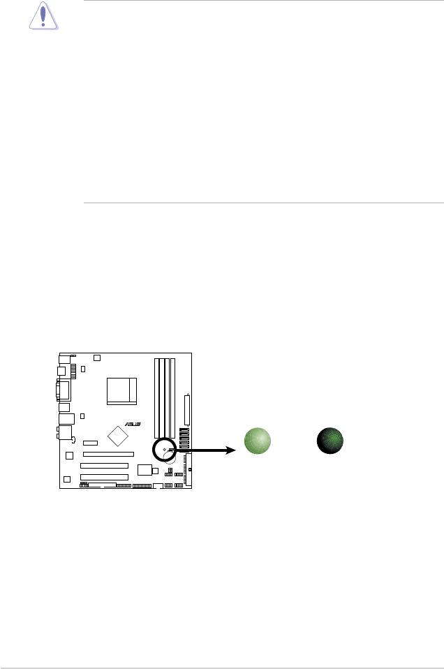
Onboard LED
The motherboard comes with a standby power LED that lights up to indicate
that the system is ON, in sleep mode, or in soft-off mode. This is a reminder
that you should shut down the system and unplug the power cable before
removing or plugging in any motherboard component. The illustration below
shows the location of the onboard LED.
1-6 Chapter 1: Product introduction
R
SB_PWR
M3N78-EMH HDMI
ON
OFF
Standby
Powered
Power
Off
M3N78-EMH HDMI Onboard LED
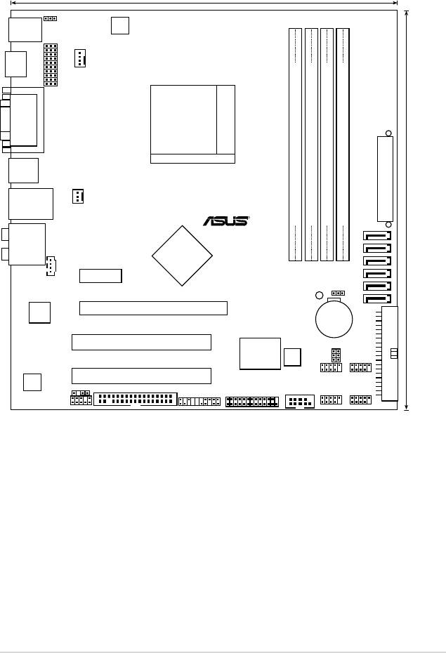
1.5 Motherboard overview
1.5.1 Motherboard layout
ASUS M3N78-EMH HDMI 1-7
23.6cm (9.3in)
PS2_USBPW1-4
PS/2KBMS
T: Mouse
B: Keyboard
ATX12V
CPU_FAN
HDMI
HDJ1
VGA_DVI
Socket AM2+
USB34
)
TXPWR
A
E
LAN1_USB12
CHA_FAN
R
24.4cm (9.6in
DDR2 DIMM_A1 (64 bit,240-pin module)
DDR2 DIMM_B1 (64 bit,240-pin module)
DDR2 DIMM_A2 (64 bit,240-pin module)
DDR2 DIMM_B2 (64 bit,240-pin module)
SATA6
AUDIO
Nvidia
SATA5
MCP78S
SATA4
CD
PCIEX1_1
SATA2
CLRTC
SATA3
SB_PWR
SATA1
Attansic
PCIEX16
L1
CR2032 3V
Lithium Cell
M3N78-EMH HDMI
CMOS Power
PRI_IDE
PCI1
Super I/O
8Mb
BIOS
USBPW5-8
USBPW9-12
PCI2
USB1112USB78
ALC662
SPDIF_OUT
FLOPP
Y
COM1
PANEL
LPT
AAFP
USB910USB56
1-8 Chapter 1: Product introduction
R
M3N78-EMH HDMI
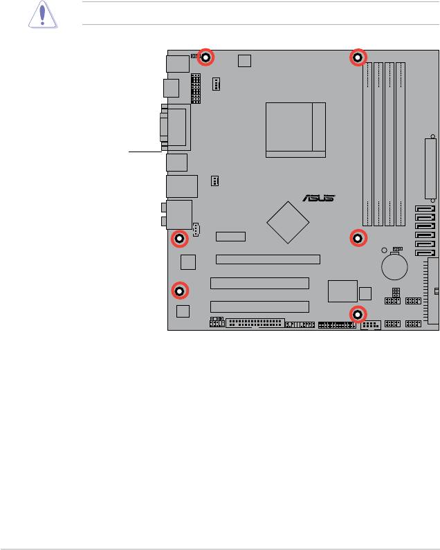
1.5.2 Placement direction
When installing the motherboard, ensure that you place it into the chassis in
the correct orientation. The edge with external ports goes to the rear part of the
chassis as indicated in the image below.
1.5.3 Screw holes
Place six (6) screws into the holes indicated by circles to secure the
motherboard to the chassis.
Do not overtighten the screws! Doing so can damage the motherboard.
Place this side towards
the rear of the chassis
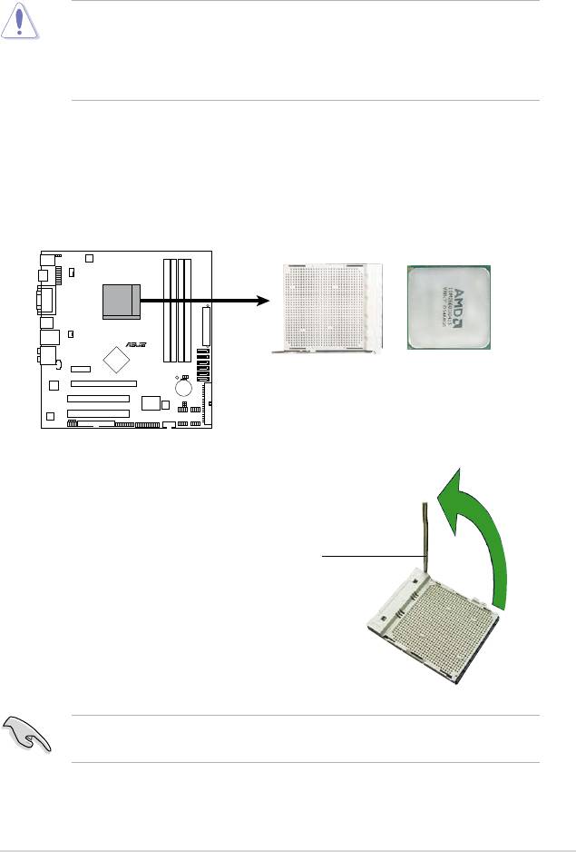
1.6 Central Processing Unit (CPU)
The motherboard comes with a 940-pin AM2+ / AM2 socket designed for the AMD
Athlon™ 64 / Sempron™ / Athlon™ FX / Athlon™ 64 X2 / AM2+ / Phenom™ FX /
Phenom™ processor.
The AM2+ / AM2 socket has a different pinout from the 940-pin socket designed
for the AMD Opteron™ processor. Ensure that you use a CPU is designed for
the AM2+ / AM2 socket. The CPU ts in only one correct orientation. DO NOT
force the CPU into the socket to prevent bending the connectors on the socket
and damaging the CPU!
1.6.1 Installing the CPU
To install a CPU.
1. Locate the CPU socket on the motherboard.
2. Unlock the socket by pressing the
lever sideways, then lift it up to a
90°-100° angle.
Socket lever
Ensure that the socket lever is lifted up to 90°-100° angle, otherwise the CPU
does not t in completely.
ASUS M3N78-EMH HDMI 1-9
R
M3N78-EMH HDMI
M3N78-EMH HDMI CPU Socket AM2+
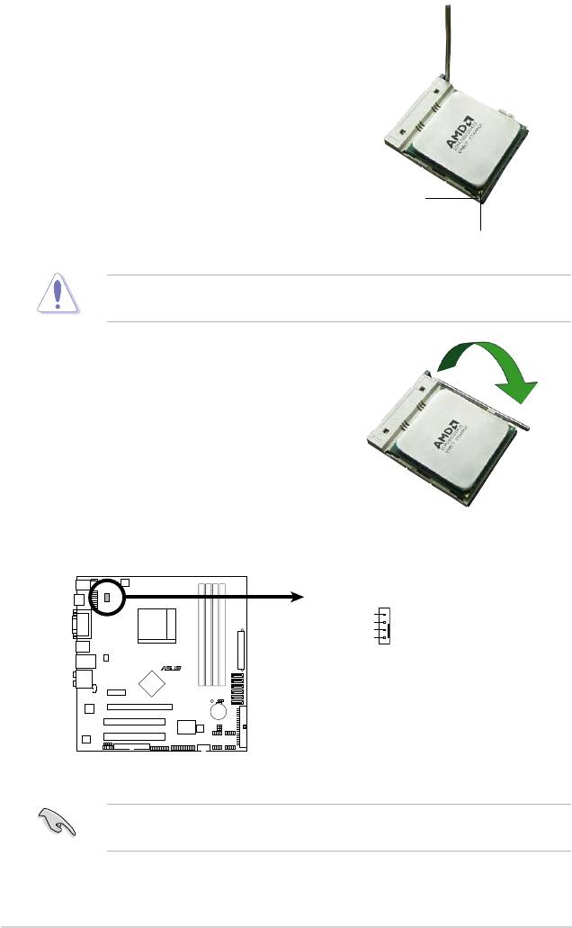
3. Position the CPU above the socket
such that the CPU corner with the
gold triangle matches the socket
corner with a small triangle.
4. Carefully insert the CPU into the
socket until it ts in place.
Small triangle
Gold triangle
The CPU ts only in one correct orientation. DO NOT force the CPU into the
socket to prevent bending the pins and damaging the CPU!
5. When the CPU is in place, push
down the socket lever to secure the
CPU. The lever clicks on the side
tab to indicate that it is locked.
6. Install a CPU heatsink and fan
following the instructions that came
with the heatsink package.
7. Connect the CPU fan cable to the CPU_FAN connector on the motherboard.
Do not forget to connect the CPU fan connector! Hardware monitoring errors
can occur if you fail to plug this connector.
1-10 Chapter 1: Product introduction
CPU_FAN
CPU FAN PWM
CPU FAN IN
CPU FAN PWR
GND
R
M3N78-EMH HDMI
M3N78-EMH HDMI CPU Fan Connector
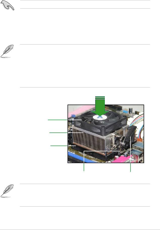
1.6.2 Installing the heatsink and fan
The AMD Athlon™ 64 / Sempron™ / Athlon™ FX / Athlon™ 64 X2 / AM2+ /
Phenom™ FX / Phenom™ processor requires a specially designed heatsink and
fan assembly to ensure optimum thermal condition and performance.
Ensure that you use only qualied heatsink and fan assembly.
Follow these steps to install the CPU heatsink and fan.
1. Place the heatsink on top of the installed CPU, ensuring that the heatsink ts
properly on the retention module base.
• The retention module base is already installed on the motherboard
upon purchase.
• You do not have to remove the retention module base when
installing the CPU or installing other motherboard components.
• If you purchased a separate CPU heatsink and fan assembly, make
sure that a Thermal Interface Material is properly applied to the CPU
heatsink or CPU before you install the heatsink and fan assembly.
CPU Fan
CPU Heatsink
Retention Module Base
Retention bracket lockRetention bracket
Your boxed CPU heatsink and fan assembly should come with installation
instructions for the CPU, heatsink, and the retention mechanism. If the
instructions in this section do not match the CPU documentation, follow the
latter.
ASUS M3N78-EMH HDMI 1-11
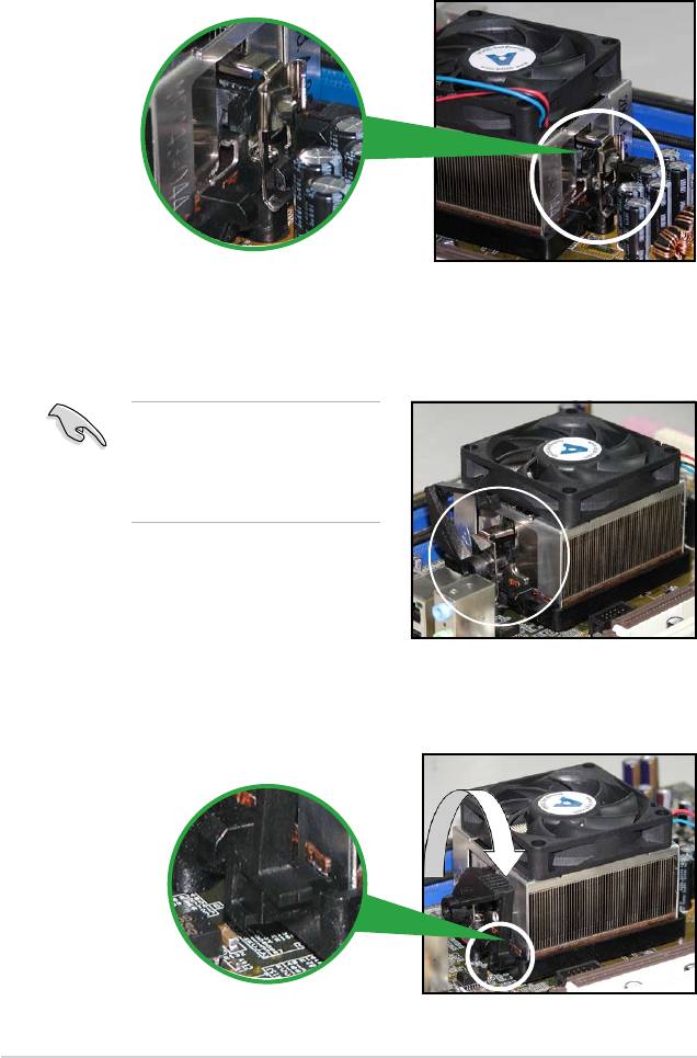
2. Attach one end of the retention bracket to the retention module base.
3. Align the other end of the retention bracket (near the retention bracket lock)
to the retention module base. A clicking sound denotes that the retention
bracket is in place.
Ensure that the fan and heatsink
assembly perfectly ts the
retention mechanism module
base. Otherwise, you cannot snap
the retention bracket in place.
4. Push down the retention bracket lock on the retention mechanism to secure
the heatsink and fan to the module base.
1-12 Chapter 1: Product introduction
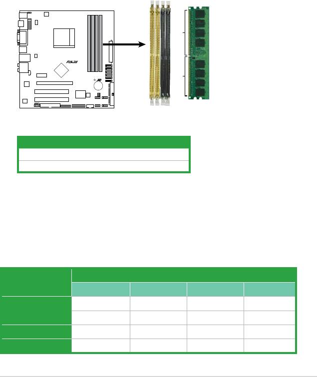
1.7 System memory
1.7.1 Overview
The motherboard comes with four Double Data Rate 2 (DDR2) Dual Inline Memory
Modules (DIMM) sockets.
A DDR2 module has the same physical dimensions as a DDR DIMM but has a
240-pin footprint compared to the 184-pin DDR DIMM. DDR2 DIMMs are notched
differently to prevent installation on a DDR DIMM socket.
The gure illustrates the location of the DDR2 DIMM sockets:
Channel Sockets
Channel A DIMM_A1 and DIMM_A2
Channel B DIMM_B1 and DIMM_B2
1.7.2 Memory congurations
You may install 256 MB, 512 MB, 1 GB, and 2 GB unbuffered ECC / non-ECC
DDR2 DIMMs into the DIMM sockets.
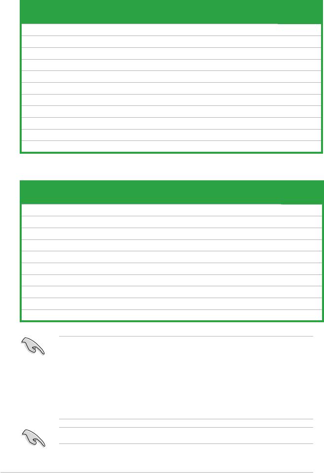
Recommended memory congurations
Sockets
Mode
DIMM_A1 DIMM_B1 DIMM_A2 DIMM_B2
– Populated – –
Single-Channel
Populated – – –
Dual-channel (1) Populated Populated – –
Dual-channel (2) Populated Populated Populated Populated
ASUS M3N78-EMH HDMI 1-13
DIMM_A1
DIMM_B1
DIMM_A2
DIMM_B2
128 Pins
R
112 Pins
M3N78-EMH HDMI
M3N78-EMH HDMI 240-pin DDR2 DIMM Sockets
• When using only one memory module, start installing the DDR2 DIMM from
slot DIMM_A1 or DIMM_B1 for better overclocking capability.
• For dual-channel conguration (2), you may:
- install identical DIMMs in all four sockets OR
- install identical DIMM pair in DIMM_A1 and DIMM_B1 (yellow sockets)
and another identical DIMM pair in DIMM_A2 and DIMM_B2 (black
sockets)
• Due to the chipset’s limitation, the 1066 MHz memory modules run at 1066
MHz only when:
- two 1066 MHz memory modules installed in the same colored-slots
(either in the yellow slots or black slots); and
- one 1066 MHz memory module installed in any of the slots.
In other cases, the 1066 MHz memory modules can only run at
800 MHz.
• Always use identical DDR2 DIMM pairs for dual channel mode. For
optimum compatibility, we recommend that you obtain memory modules
from the same vendor.
• If you are using a Windows 32-bit version operating system (e.g. 32-bit
Windows, 32-bit Vista) without the Physical Address Extension (PAE)
support, the system will allocate a certain amount of memory space for
system devices.
• We recommend that you install only a maximum of 3GB system memory
when using a Windows 32-bit version operating system without the PAE.
The excess over 3GB of installed memory will not cause any problem;
however, the system can not use this excess memory space and the
system will display less than the total size of physical memory installed.
The motherboard can support 8 GB physical memory on the operating system
listed below. You may install a maximum of 2 GB DIMMs on each slot.
64-bit
®
Windows
XP Professional x64 Edition
®
Windows
Vista x64 Edition
1-14 Chapter 1: Product introduction

Qualied Vendors Lists (QVL)
DDR2-533 MHz capability
Size Vendor Model CL Brand SS/
Component DIMM support
DS
A* B* C*
512MB Kingston KVR533D2N4/512 N/A Inneon SS HYB18T512800AF3733336550 · ·
512MB Samsung M378T6553BG0-CD5 4 Samsung SS K4T51083QB-GCD5 · ·
1G HY HYMP512U64CP8-C4 AB 4 Hynix DS HY5PS12821CFP-C4 · ·
512MB Micron MT 16HTF6464AG-53EB2 4 Micron DS D9BOM · ·
1G Corsair VS1GB533D2 N/A Corsair DS 64M8CFEGQIB0900718 · ·
512MB Elpida EBE51UD8ABFA-5C-E N/A Elpida SS E5108AB-5C-E · ·
512MB Transcend 512MB ECC N/A Micron SS 6ND22D9GCT(ECC) · ·
512MB ADATA M2OAD2G3H3166I1B52 N/A ADATA SS AD29608A8A-37DG20719 · ·
DDR2-667 MHz capability
Size Vendor Model CL Brand SS/
Component DIMM support
DS
A* B* C*
2G Kingston KVR667D2N5/2G N/A Micron DS 7RE22 D9HNL · ·
512MB Samsung M378T6553CZ3-CE6 N/A Samsung SS K4T51083QC-ZCE6 · ·
2G Qimonda HYS64T256020EU-3S-B 5 Qimonda DS HTB18T1G800BF-3S3VV10907 · ·
1G Corsair VS1GB667D2 N/A Corsair DS MID095D62864M8CEC · ·
1G HY HYMP512U72AP8-Y5 N/A Hynix DS HY5PS12821AFP-Y5(ECC) · ·
1G HY HYMP512U64CP8-Y5 AB 5 Hynix DS HY5PS12521CFP-Y5 · ·
512MB Kingmax KLCC28F-A8KB5 N/A Kingmax SS KKEA88B4LAUG-29DX · ·
512MB Apacer AU512E667C5KBGC 5 Apacer SS AM4B5708MIJS7E0627B · ·
1G Apacer AU01GE667C5KBGC 5 Apacer DS AM4B5708MIJS7E0627B · ·
512MB ADATA M20AD5G3H3166I1C52 N/A ADATA SS AD29608A8A-3EG20648 · ·
512MB ADATA M20AD5G3H3166I1C52 N/A ADATA SS AD29608A8A-3EG20718 · ·
512MB VDATA M2GVD5G3H31A4I1C52 N/A VDATA SS VD29608A8A-3EC20615 · ·
1G VDATA M2GVD5G3I41C4I1C52 N/A VDATA DS VD29608A8A-3EC20620 · ·
1G PSC AL7E8E63B-6E1K 5 PSC DS A3R12E3GEF637BLC5N · ·
1G PSC AL7E8F73C-6E1 5 PSC SS A3R1GE3CFF734MAA0J · ·
512MB Nanya NT512T64U88A1BY-3C N/A Nanya SS NT5TU64M8AE-3C · ·
1G Kingtiger E0736001024667 N/A Kingtiger DS KTG667PS6408NST-C6 GDBTX · ·
(continued on the next page)
ASUS M3N78-EMH HDMI 1-15
Qualied Vendors Lists (QVL)
DDR2-800 MHz capability
Size Vendor Model CL Brand SS/
Component DIMM support
DS
A* B* C*
1G Kingston KHX6400D2LL/1G N/A Kingston DS Heat-Sink Package · ·
1G Samsung KR M378T2953CZ3-CE7 N/A Samsung DS K4T51083QC-ZCE7 · ·
1G Samsung KR M391T2953CZ3-CE7 N/A Samsung DS K4T51083QC-ZCE7(ECC) · ·
512MB Qimonda HYS64T64000EU-2.5-B2 6 Qimonda SS HYB18T512800B2F25FSS28380 · ·
1G Micron MT18HTF12872AY-80ED4 5 Micron DS 6TD22D9GKX(ECC) · ·
1G Corsair XMS2-6400 5 Corsair DS Heat-Sink Package · ·
1G HY HYMP512U64AP8-S6 AA N/A Hynix DS HY5PS12821AFP-S6 · ·
2G Apacer 78.A1GA0.9K4 5 Apacer DS AM4B5808CQJS8E0740E · ·
512MB ADATA M20AD6G3H3160I1E58 N/A ADATA SS AD29608A8A-25EG80720 · ·
1G VDATA M2GVD6G3I4170I1E53 N/A VDATA DS VD29608A8A-25EG30647 · ·
1G PSC AL7E8F73C-8E1 5 PSC SS A3R1GE3CFF734MAA0E · ·
DDR2-1066 MHz capability
Size Vendor Model CL Brand SS/
Component DIMM support
DS
A* B* C*
512MB Kingston KHX8500D2/512 N/A Kingston SS Heat-Sink Package · · ·
512MB Kingston KHX8500D2K2/1GN N/A Kingston SS Heat-Sink Package · ·
1G Kingston KHX8500D2K2/2GN N/A Kingston DS Heat-Sink Package · · ·
1G Qimonda HYS64T128020EU-19F-C 6 Qimonda DS HYB18T512800CF19FFSS24313 · · ·
1G Corsair CM2X1024-8500C5 N/A Corsair DS Heat-Sink Package · ·
1G Corsair CM2X1024-8500C5D 5 Corsair DS Heat-Sink Package · · ·
512MB ADATA M2OMIDG3H3160INC5Z 5 ADATA SS Heat-Sink Package · · ·
1G ADATA M2OMIDG314720INC5Z 5 ADATA DS Heat-Sink Package · · ·
1G OCZ OCZ2N10662GK N/A OCZ DS Heat-Sink Package · · ·
1G GEIL M016E2864T2AGXAKT7G330520 5 Micron DS 7KD22D9GMH · · ·
SS - Single-sided / DS - Double - sided
DIMM support:
• A*: Supports one module inserted into any slot as Single-channel memory
conguration.
• B*: Supports one pair of modules inserted into either the yellow slots or the
black slots as one pair of Dual-channel memory conguration.
• C*: Supports four modules inserted into both the yellow slots and the black
slots as two pairs of Dual-channel memory conguration.
Visit the ASUS website for the latest DDR2-667/800/1066MHz QVL.
1-16 Chapter 1: Product introduction
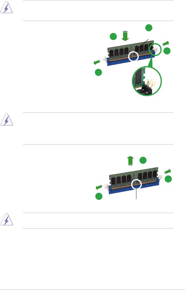
1.7.3 Installing a DIMM
Ensure to unplug the power supply before adding or removing DIMMs or other
system components. Failure to do so may cause severe damage to both the
motherboard and the components.
2
1. Unlock a DIMM socket by pressing
3
DDR2 DIMM notch
the retaining clips outward.
2. Align a DIMM on the socket such
1
that the notch on the DIMM matches
the break on the socket.
3. Firmly insert the DIMM into the
1
socket until the retaining clips snap
back in place and the DIMM is
properly seated.
Unlocked retaining clip
• A DDR2 DIMM is keyed with a notch so that it ts in only one
direction. DO NOT force a DIMM into a socket to avoid damaging the
DIMM.
• The DDR2 DIMM sockets do not support DDR DIMMs. Do not install
DDR DIMMs to the DDR2 DIMM sockets.
2
1.7.4 Removing a DIMM
To remove a DIMM:
1
1
1. Simultaneously press the retaining
clips outward to unlock the DIMM.
1
DDR2 DIMM notch
Support the DIMM lightly with your ngers when pressing the retaining clips.
The DIMM might get damaged when it ips out with extra force.
2. Remove the DIMM from the socket.
ASUS M3N78-EMH HDMI 1-17

1.8 Expansion slots
In the future, you may need to install expansion cards. The following sub-sections
describe the slots and the expansion cards that they support.
Ensure to unplug the power cord before adding or removing expansion cards.
Failure to do so may cause you physical injury and damage motherboard
components.
1.8.1 Installing an expansion card
To install an expansion card:
1. Before installing the expansion card, read the documentation that came with
it and make the necessary hardware settings for the card.
2. Remove the system unit cover (if your motherboard is already installed in a
chassis).
3. Remove the bracket opposite the slot that you intend to use. Keep the screw
for later use.
4. Align the card connector with the slot and press rmly until the card is
completely seated on the slot.
5. Secure the card to the chassis with the screw you removed earlier.
6. Replace the system cover.
1.8.2 Conguring an expansion card
After installing the expansion card, congure it by adjusting the software settings.
1. Turn on the system and change the necessary BIOS settings, if any. See
Chapter 2 for information on BIOS setup.
2. Assign an IRQ to the card. Refer to the tables on the next page.
3. Install the software drivers for the expansion card.
1-18 Chapter 1: Product introduction

Interrupt assignments
IRQ Standard function
0 Standard timer
1 Keyboard
2 High precision event timer
3 IRQ holder for PCI steering
4 COM1
5 IRQ holder for PCI steering
6 Floppy controller
7 Printer port
8 High precision event timer
9 AMD ACPI-Compliant system
10 IRQ holder for PCI steering
11 IRQ holder for PCI steering
12 Microsoft PS/2 mouse
13 Numeric data processor
14 Primary IDE
15 Slave IDE
* These IRQs are usually available for ISA or PCI devices.
ASUS M3N78-EMH HDMI 1-19
IRQ assignments for this motherboard
LNKA LNKB LN0A LN2A LATA UB12 UB11 LUB2 LUB0 LPMU LSMB LMAC LSA0 LAZA SGRU
PCI slot1 shared - - - - - - - - - - - - - -
PCI slot2 - shared - - - - - - - - - - - - -
PCI EX1
- - - shared - - - - - - - - - - -
Slot
PCI EX16
- - shared - - - - - - - - - - - -
slot
Onboard
- - - - - - - - shared - - - - - -
USB1.1
(OHCI)
Onboard
- - - - - - shared - - - - - - - -
USB 1.1
(OHCI)
Onboard
- - - - - shared - - - - - - - - -
USB2.0
(EHCI)
Onboard
- - - - - - - shared - - - - - - -
USB2.0
(EHCI)
Onboard
- - - - shared - - - - - - - - - -
IDE
controller
Onboard
- - - - - - - - - - - - shared - -
SATA
controller
Onboard
- - - - - - - - - - shared - - - -
SMBus
controller
Onboard
- - - - - - - - - - - - - shared -
Azalia
controller
Onboard
- - - - - - - - - - - shared - - -
LAN
8111B
Onboard
- - - - - - - - - shared - - - - -
PMU
device
IXVE Bus
- - - - - - - - - - - - - - shared
Bridge
Onboard
- - - - - - - - - - - - - - shared
VGA
When using PCI cards on shared slots, ensure that the drivers support “Share
IRQ” or that the cards do not need IRQ assignments. Otherwise, conicts will
arise between the two PCI groups, making the system unstable and the card
inoperable.
1-20 Chapter 1: Product introduction
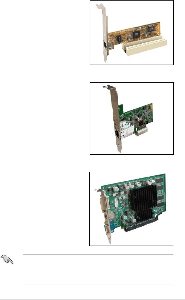
1.8.3 PCI slots
The PCI slots support cards such as
a LAN card, SCSI card, USB card,
and other cards that comply with PCI
specications. The gure shows a LAN
card installed on a PCI slot.
1.8.4 PCI Express x1 slot
This motherboard supports PCI Express
x1 network cards, SCSI cards and other
cards that comply with the PCI Express
specications. The following gure
shows a network card installed on the
PCI Express x1 slot.
1.8.5 PCI Express x16 slot
This motherboard has supports PCI
Express x16 graphic cards that comply
with PCI Express specications. The
gure shows a graphics card installed on
the PCI Express x16 slot.
®
®
• Currently, only NVIDIA
GeForce
8500 GT and GeForce 8400 GS
TM
graphics cards support GeForce Boost function under Hybrid SLI
mode.
®
®
• Currently, only NVIDIA
GeForce
9800 GX2 and GeForce 9800 GTX
TM
graphics cards support Hybrid Power function under Hybrid SLI
mode.
ASUS M3N78-EMH HDMI 1-21
1.9 Jumpers
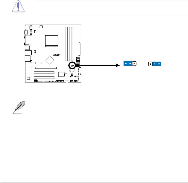
1. Clear RTC RAM (CLRTC)
This jumper allows you to clear the Real Time Clock (RTC) RAM in
CMOS. You can clear the CMOS memory of date, time, and system setup
parameters by erasing the CMOS RTC RAM data. The onboard button
cell battery powers the RAM data in CMOS, which include system setup
information such as system passwords.
To erase the RTC RAM:
1. Turn OFF the computer and unplug the power cord.
2. Remove the onboard battery.
3. Move the jumper cap from pins 1-2 (default) to pins 2-3. Keep the cap on pins
2-3 for about 5~10 seconds, then move the cap back to pins 1-2.
4. Reinstall the battery.
5. Plug the power cord and turn ON the computer.
6. Hold down the <Del> key during the boot process and enter BIOS setup to
re-enter data.
Except when clearing the RTC RAM, never remove the cap on CLRTC jumper
default position. Removing the cap will cause system boot failure!
You do not need to clear the RTC when the system hangs due to overclocking.
For system failure due to overclocking, use the C.P.R. (CPU Parameter Recall)
feature. Shut down and reboot the system so the BIOS can automatically reset
parameter settings to default values.
1-22 Chapter 1: Product introduction
R
CLRTC
1 2
2 3
M3N78-EMH HDMI
Normal Clear RTC
(Default)
M3N78-EMH HDMI Clear RTC RAM
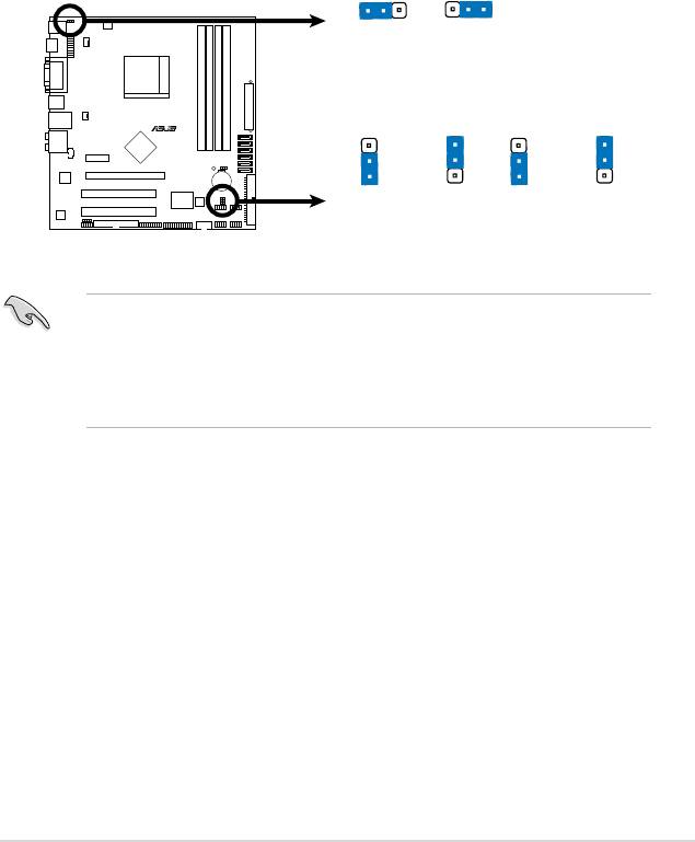
2. USB device wake-up (3-pin PS2_USBPW1-4, USBPW5-8, USBPW9-12)
Set these jumpers to +5V to wake up the computer from S1 sleep mode
(CPU stopped, DRAM refreshed, system running in low power mode) using
the connected USB devices. Set to +5VSB to wake up from S3 and S4 sleep
modes.
The USBPW1-4 jumpers are for the rear USB ports. The USBPW5-8 and
USBPW910 jumpers are for the internal USB connectors that you can
connect to additional USB ports.
• The USB device wake-up feature requires a power supply that can
provide 500mA on the +5VSB lead for each USB port. Otherwise,
the system will not power up.
• The total current consumed must NOT exceed the power supply
capability (+5VSB) whether under normal condition or in sleep mode.
ASUS M3N78-EMH HDMI 1-23
PS2_USBPW1-4
1
2
2
3
+5
V
+5VSB
(D
e
fa
u
lt
)
USBPW5-8
USBPW9-12
R
3
3
2
2
2
2
1
1
M3N78-EMH HDMI
+5
V
+5VSB
+5
V
+5VSB
(Defau
lt
)
(Defau
lt
)
M3N78-EMH HDMI
USB Device Wake Up
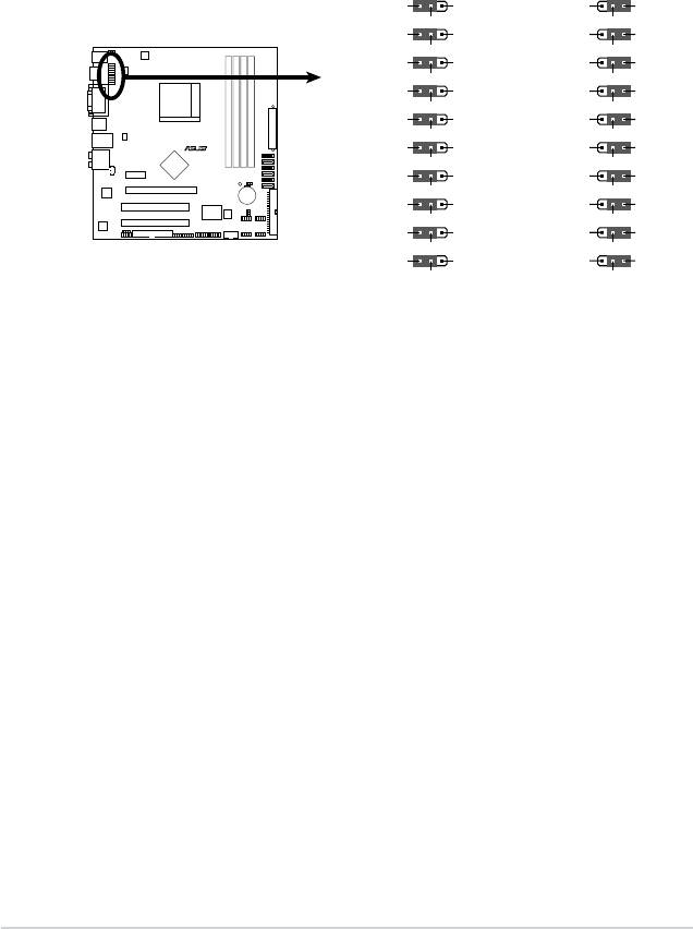
3. HDJ1 Setting
This jumper allows you to switch between the HDMI and the DVI features.
Set this jumper to pins 1-2 (HDMI) to enable the HDMI feature. Set this
jumper to pins 2-3 to enable the DVI feature.
1-24 Chapter 1: Product introduction
HDJ1
1
2 2 3
HDMI TXCON
DV
I T
XCON
HDMI TXCON
DV
I T
XCO
N
HDM/DVI_TXCON 14
HDM/DVI_TXCON 14
HDMI TXCOP
DV
I T
X
CO
P
HDMI TXCOP
DV
I T
X
CO
P
HDM/DVI_TXCOP 14
HDM/DVI_TXCOP 14
HDMI TXDOP
DV
I T
X
DO
P
HDMI TXDOP
DV
I TX
DO
P
HDM/DVI_TX
DOP
13
HDM/DVI_TX
DOP
13
HDMI TXDON
DV
I T
X
DO
N
HDMI TXDON
DV
I T
X
DO
N
HDM/DVI_TXDON 13
HDM/DVI_TXDON 13
HDMI TXD2N
DV
I T
X
D2N
HDMI TXD2N
DV
I TX
D2N
HDM/DVI_TXD2N 14
HDM/DVI_TXD2N 14
R
HDMI TXD2P
DV
I T
X
D2P
HDMI TXD2P
DV
I T
X
D2P
HDM/DVI_TXD2P 14
HDM/DVI_TXD2P 14
HDMI TXD1P
DV
I T
X
D1P
HDMI TXD1P
DV
I T
X
D1P
M3N78-EMH HDMI
HDM/DVI_TXD1P 14
HDM/DVI_TXD1P 14
HDMI TXD1N
DV
I T
X
D1N
HDMI TXD1N
DV
I T
X
D1N
HDM/DVI_TXD1N 14
HDM/DVI_TXD1N 14
HDMI_SCL
DV
I
_SCL
HDMI_SCL
DV
I
_SCL
SCL
SCL
M3N78-EMH HDMI HDJ1 Setting
HDMI_SDA
DVI_SD
A
HDMI_SDA
DVI_SD
A
SDA
SDA
HDMI
DVI
(Default)
1.10 Connectors
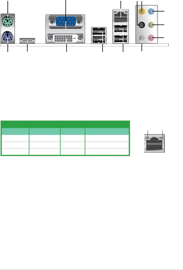
1.10.1 Rear panel connectors
1. PS/2 mouse port (green). This port is for a PS/2 mouse.
2. Video Graphics Adapter (VGA) port
. This 15-pin port is for a VGA monitor
or other VGA-compatible devices.
3. LAN (RJ-45) port. Supported by Marvell Gigabit LAN controller, this port
allows Gigabit connection to a Local Area Network (LAN) through a network
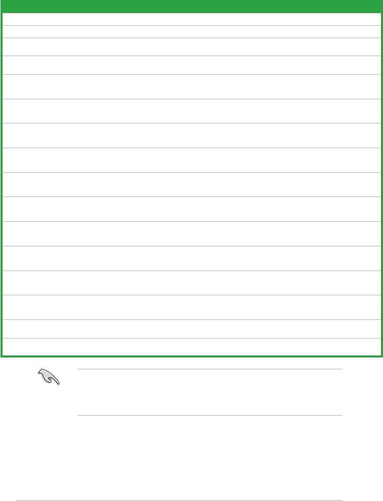
hub. Refer to the table below for the LAN port LED indications.
LAN port LED indications
ACT/LINK
SPEED
Activity/Link LED Speed LED
LED
LED
Status Description Status Description
OFF No link OFF 10 Mbps connection
ORANGE Linked ORANGE 100 Mbps connection
BLINKING Data activity GREEN 1 Gbps connection
LAN port
4. Rear Speaker Out port (black).
This port connects the rear speakers in a
4-channel, 6-channel, or 8-channel audio conguration..
5. Center / Subwoofer port (orange).
This port connects the center /
subwoofer speakers.
6. Line In port (light blue)
. This port connects the tape, CD, DVD player, or
other audio sources.
7. Line Out port (lime)
. This port connects a headphone or a speaker. In
4-channel, 6-channel, and 8-channel conguration, the function of this port
becomes Front Speaker Out.
8. Microphone port (pink).
This port connects a microphone.
9. Side Speaker Out port (gray)
. This port connects the side speakers in an
8-channel audio conguration.
ASUS M3N78-EMH HDMI 1-25
1 3
2
4
5
6
7
8
1011121314
9
Refer to the audio conguration table below for the function of the audio ports in
2, 4, 6 or 8-channel conguration.
Audio 2, 4, 6, or 8-channel conguration
Port Headset
4-channel 6-channel 8-channel
2-channel
Light Blue Line In Line In Line In Line In
Lime Line Out Front Speaker Out Front Speaker Out Front Speaker Out
Pink Mic In Mic In Mic In Mic In
Orange – – Center/Subwoofer Center/Subwoofer
Black – Rear Speaker Out Rear Speaker Out Rear Speaker Out
Gray – – – Side Speaker Out
10. USB 2.0 ports 1 and 2. These two 4-pin Universal Serial Bus (USB) ports
are available for connecting USB 2.0 devices.
11. USB 2.0 ports 3 and 4. These two 4-pin Universal Serial Bus (USB) ports
are available for connecting USB 2.0 devices.
12. DVI port. This port is for any DVI-D compatible device. DVI-D can’t be
converted to output RGB Signal to CRT and isn’t compatible with DVI-I.
13. HDMI port. This port is for a High-Denition Multimedia Interface (HDMI)
connector, and is HDCP compliant allowing playback of HD DVD, Blu-Ray
and other protected content
• This motherboard comes with dual-VGA output. If you connect 2 monitors
to both VGA and DVI-D / HDMI out ports, each controller can drive same or
different display contents to different resolutions and refresh rates.
• Due to the chipset limitation, simultaneous output for DVI and HDMI is not
supported. See page 1-23 for details.
• To play HD DVD or BLU-Ray Disc, ensure to use an HDCP compliant
monitor.
Playback of HD DVD and Blu-Ray Discs
The speed and bandwidth of the CPU/Memory, DVD player, and drivers
will affect the playback quality. Using the CPU/Memory of higher speed and
bandwidth with the higher-version DVD player and drivers will upgrade the
playback quality.
14. PS/2 keyboard port (purple). This port is for a PS/2 keyboard.
1-26 Chapter 1: Product introduction
1.10.2 Internal connectors
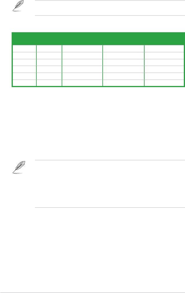
1. Floppy disk drive connector (34-1 pin FLOPPY)
This connector is for the provided oppy disk drive (FDD) signal cable. Insert
one end of the cable to this connector, then connect the other end to the
signal connector at the back of the oppy disk drive.
Pin 5 on the connector is removed to prevent incorrect cable connection when
using an FDD cable with a covered Pin 5.
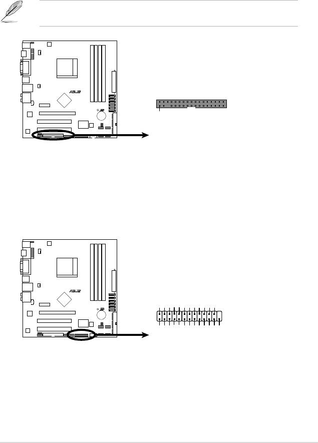
2. LPT connector
The LPT (Line Printing Terminal) connector supports devices such as a
printer. LPT standardizes as IEEE 1284, which is the parallel port interface on
IBM PC-compatible computers.
ASUS M3N78-EMH HDMI 1-27
R
FLOPPY
M3N78-EMH HDMI
PIN1
NOTE:
Orient the red markings on
the floppy ribbon cable to PIN 1.
M3N78-EMH HDMI
Floppy Disk Drive Connector
LPT
R
INIT#
AFD
GND
GND
GND
GND
GND
GND
GND
M3N78-EMH HDMI
1
STB#
PD0ERR#
PD1
PD2SLIN#
PD3GND
PD4
PD5
PD6
PD7
ACK#
BUSY
PE
SLCT
M3N78-EMH HDMI
Parallel Port Connector
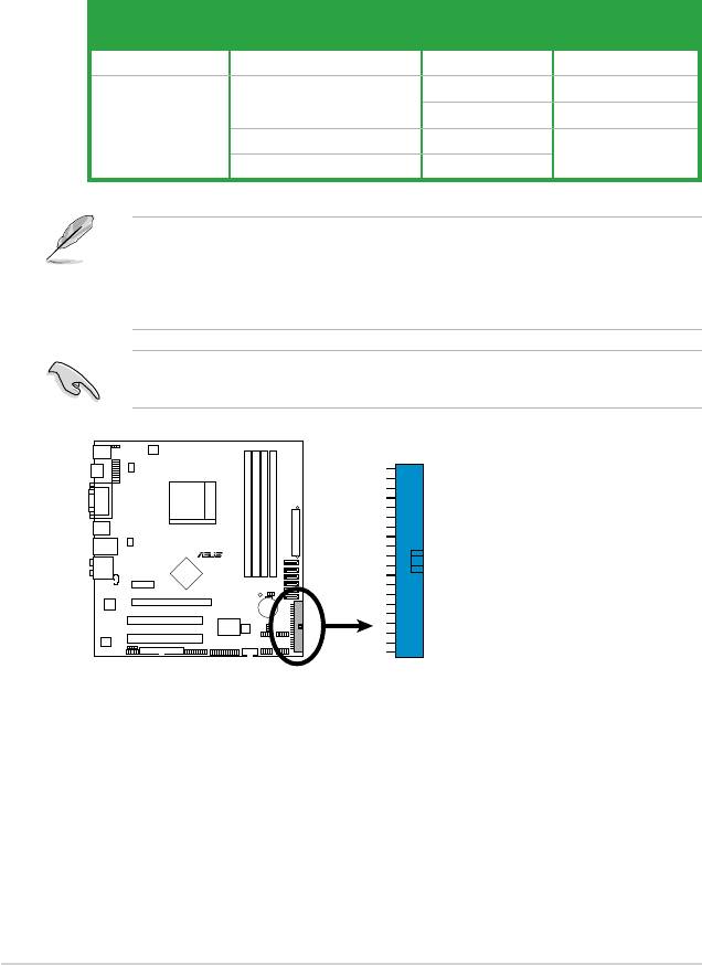
3. IDE connectors (40-1 pin PRI_IDE)
The onboard IDE connector is for an Ultra DMA 133/100/66 signal cable.
There are three connectors on each Ultra DMA 133/100/66 signal cable:
blue, black, and gray. Connect the blue connector to the motherboard’s IDE
connector, then select one of the following modes to congure your device(s).
Drive jumper setting Mode of
Cable connector
device(s)
Single device Cable-Select or Master - Black
Black
Two devices Cable-Select Master
Slave Gray
Master Master Black or gray
Slave Slave
• Pin 20 on the IDE connector is removed to match the covered hole on the
Ultra DMA cable connector. This prevents incorrect insertion when you
connect the IDE cable.
• Use the 80-conductor IDE cable for Ultra DMA 133/100/66 IDE devices.
If any device jumper is set as “Cable-Select,” ensure that all other device
jumpers have the same setting.
1-28 Chapter 1: Product introduction
R
M3N78-EMH HDMI
PRI_IDE
M3N78-EMH HDMI
IDE Connector
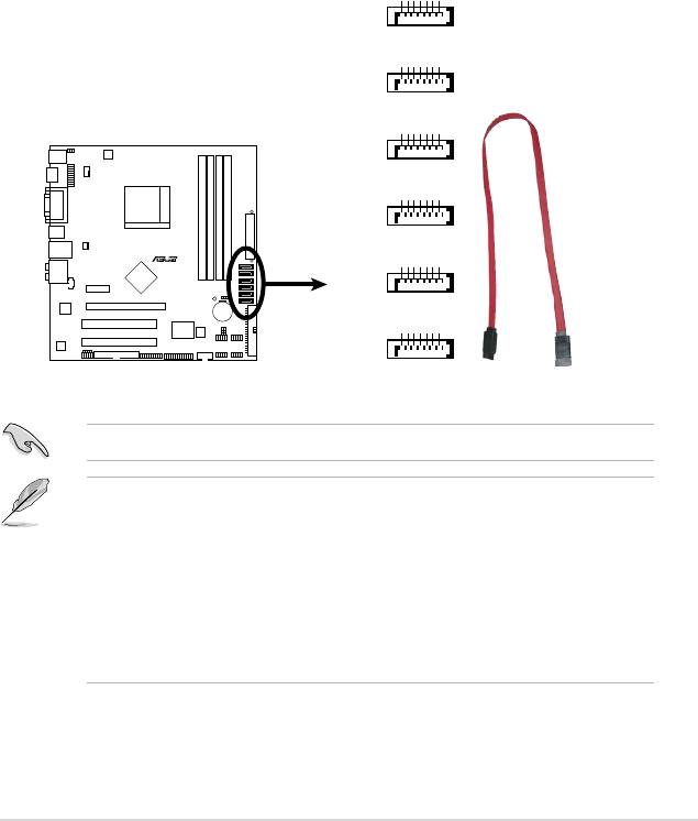
4. Serial ATA connectors (7-pin SATA1 [red], SATA2 [red], SATA3 [red],
SATA4 [red], SATA5 [black], SATA6 [black])
These connectors are for the Serial ATA signal cables for Serial ATA
3Gb/s hard disk and optical disk drives. The Serial ATA 3Gb/s is backward
compatible with Serial ATA 1.5Gb/s specication. The data transfer rate of the
Serial ATA 3Gb/s is faster than the standard parallel ATA with 133 MB/s (Ultra
DMA133).
If you install Serial ATA hard disk drives, you can create a RAID 0, RAID 1,
RAID 5, RAID 0+1, and JBOD conguration through the onboard controller.
®
Install the Windows
XP Service Pack 1 before using Serial ATA.
• For detailed instructions on how to congure RAID 0, RAID 1, RAID 5, and
RAID 10, and JBOD, refer to the RAID manual in the support DVD.
• If you intend to create a Serial ATA RAID set using these connectors, set
the SATA Mode select item in the BIOS to [RAID Mode]. See the
page 2-16 for details.
• Due to the chipset’s limitation, SATA 5 and SATA 6 do not support IDE
mode, only support AHCI+RAID mode.
ASUS M3N78-EMH HDMI 1-29
A_RXN6
GND
RSAT
RSATA_RXP6
GND
RSATA_TXN6
RSATA_TXP6
GND
SATA6
A_RXN5
GND
RSAT
RSATA_RXP5
GND
RSATA_TXN5
RSATA_TXP5
GND
SATA5
A_RXN4
GND
RSAT
RSATA_RXP4
GND
RSATA_TXN4
RSATA_TXP4
GND
SATA4
A_RXN2
GND
RSAT
RSATA_RXP2
GND
RSATA_TXN2
RSATA_TXP2
GND
SATA2
A_RXN3
R
GND
RSAT
RSATA_RXP3
GND
RSATA_TXN3
RSATA_TXP3
GND
SATA3
M3N78-EMH HDMI
A_RXN1
GND
RSAT
RSATA_RXP1
GND
RSATA_TXN1
RSATA_TXP1
GND
SATA1
M3N78-EMH HDMI
SATA Connectors
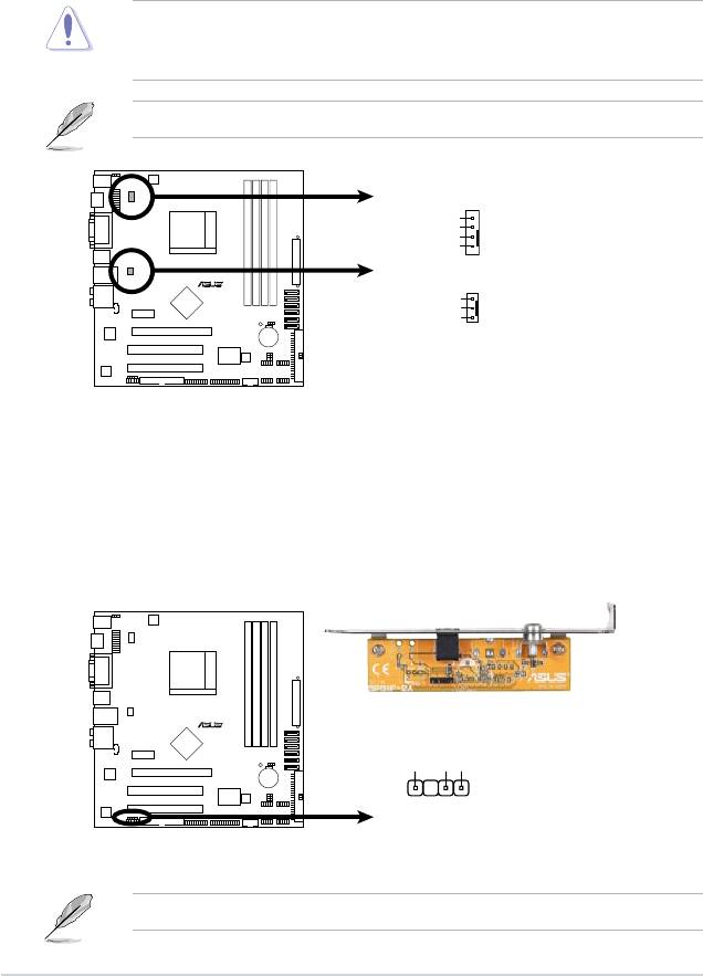
5. CPU and Chassis Fan connectors (4-pin CPU_FAN, 3-pin CHA_FAN)
The fan connectors support cooling fans of 350mA~740mA (8.88W max.) or
a total of 1A~2.22A (26.64W max.) at +12V. Connect the fan cables to the fan
connectors on the motherboard, ensuring that the black wire of each cable
matches the ground pin of the connector.
Do not forget to connect the fan cables to the fan connectors. Insufcient air
ow inside the system may damage the motherboard components. These are
not jumpers! DO NOT place jumper caps on the fan connectors.
Only CPU Fan supports Q-Fan.
6. Digital audio connector (4-1 pin SPDIF_OUT)
This connector is for an additional Sony/Philips Digital Interface (S/PDIF)
port(s). Connect the S/PDIF module cable to this connector, then install the
module to a slot opening at the back of the system chassis.
The S/PDIF module is purchased separately.
1-30 Chapter 1: Product introduction
SPDIFOUT
R
GND
+5V
M3N78-EMH HDMI
SPDIF_OUT
M3N78-EMH HDMI
Digital Audio Connector
CPU_FAN
CPU FAN PWM
CPU FAN IN
CPU FAN PWR
GND
R
CHA_FAN
Rotation
+12V
GND
M3N78-EMH HDMI
M3N78-EMH HDMI Fan Connectors
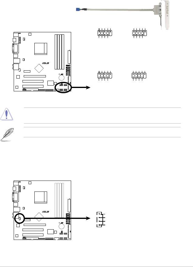
7. USB connectors (10-1 pin USB56, USB78, USB910, USB1112)
These connectors are for USB 2.0 ports. Connect the USB module cable
to any of these connectors, then install the module to a slot opening at the
back of the system chassis. These USB connectors comply with USB 2.0
specication that supports up to 480 Mbps connection speed.
Never connect a 1394 cable to the USB connectors. Doing so will damage the
motherboard!
The USB 2.0 module is purchased separately.
8. Optical drive audio in connector (4-pin CD)
These connectors allow you to receive stereo audio input from sound sources
such as a CD-ROM, TV tuner, or MPEG card.
ASUS M3N78-EMH HDMI 1-31
CD
(black)
R
Right Audio Channel
Ground
Ground
M3N78-EMH HDMI
Left Audio Channel
M3N78-EMH HDMI
Internal Audio Connector
USB+5V
USB_P8-
USB_P8+
GND
NC
USB+5V
USB_P12-
USB_P12+
GND
NC
USB78
USB1112
1
1
GND
GND
USB+5V
USB_P7-
USB+5V
USB_P7+
USB_P11-
USB_P11+
R
USB+5V
USB_P6-
USB_P6+
GND
NC
USB+5V
USB_P10-
USB_P10+
GND
NC
USB56
USB910
M3N78-EMH HDMI
1
1
GND
GND
USB+5V
USB_P5-
USB+5V
USB_P5+
USB_P9-
USB_P9+
M3N78-EMH HDMI USB 2.0 Connectors
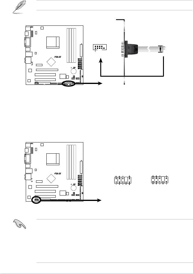
9. Serial port connectors (10-1 pin COM1)
The connector is for a serial (COM) port. Connect the serial port module
cable to the connector, then install the module to a slot opening at the back of
the system chassis.
The serial port bracket (COM1) is purchased separately.
10. Front panel audio connector (10-1 pin AAFP)
This connector is for a chassis-mounted front panel audio I/O module that
supports either High Denition Audio or AC`97 audio standard. Connect one
end of the front panel audio I/O module cable to this connector.
• We recommend that you connect a high-denition front panel audio module
to this connector to avail of the motherboard high-denition audio capability.
• If you want to connect a high-denition front panel audio module to this
connector, ensure that the Front Panel Type item in the BIOS is set to [HD
Audio]; if you want to connect an AC`97 front panel audio module to this
connector, set the item to [AC97]. See page 2-29 for details.
1-32 Chapter 1: Product introduction
Azalia-compliant
Legacy AC’97-compliant
pin definition
pin definition
R
AGND
PRESENSE#
MIC2_JD
HP_HD
AGND
NC
NC
NC
AAFP
M3N78-EMH HDMI
NC
HP_R
HP_L
MIC2_L
MIC2_L
MIC2_R
MIC2_R
Line out_R
Line out_L
Jack_Sense
M3N78-EMH HDMI Azalia Analog Front Panel Connector
COM1
R
PIN1
M3N78-EMH HDMI
M3N78-EMH HDMI
COM Port Connector
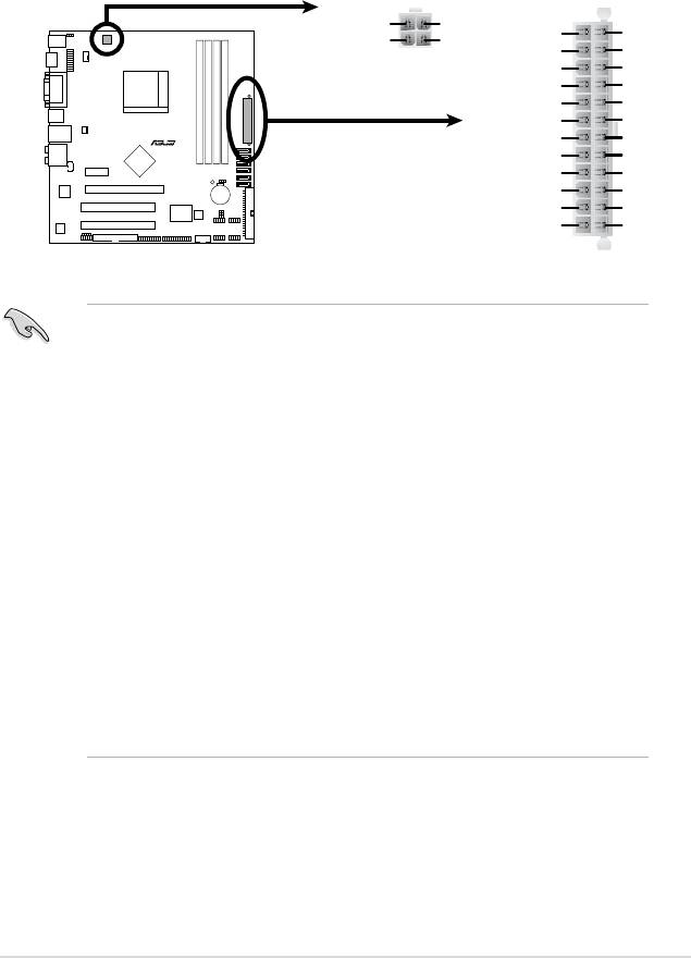
11. ATX power connectors (24-pin ATX-PWRGD, 4-pin ATX12V)
These connectors are for an ATX power supply. The plugs from the power
supply are designed to t these connectors in only one orientation. Find the
proper orientation and push down rmly until the connectors completely t.
•
We recommend that you use an ATX 12 V Specication 2.0-compliant
power supply unit (PSU) with a minimum of 300 W power rating. This PSU
type has 24-pin and 4-pin power plugs.
•
If you intend to use a PSU with 20-pin and 4-pin power plugs, ensure that
the 20-pin power plug can provide at least 15 A on +12 V and that the PSU
has a minimum power rating of 300 W. The system may become unstable
or may not boot up if the power is inadequate.
•
Do not forget to connect the 4-pin ATX +12 V power plug. Otherwise, the
system will not boot up.
• We recommend that you use a PSU with higher power output when
conguring a system with more power-consuming devices. The system
may become unstable or may not boot up if the power is inadequate.
• If you are uncertain about the minimum power supply requirement for your
system, refer to the Recommended Power Supply Wattage Calculator
at http://support.asus.com/PowerSupplyCalculator/PSCalculator.
aspx?SLanguage=en-us for details.
•
You must install a PSU with a higher power rating if you intend to install
additional devices.
ASUS M3N78-EMH HDMI 1-33
ATX12V
EATXPWR
+12V DC
+12V DC
+3 Volts
Ground
GND
GND
+12 Volts
+5 Volts
+12 Volts
+5 Volts
+5V Standby
+5 Volts
Power OK
-5 Volts
Ground
Ground
R
+5 Volts
Ground
Ground
Ground
+5 Volts
PSON#
Ground
Ground
M3N78-EMH HDMI
+3 Volts
-12 Volts
+3 Volts
+3 Volts
M3N78-EMH HDMI ATX Power Connector
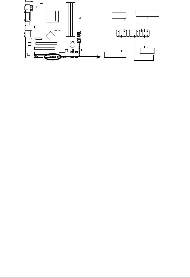
12. System panel connector (20-8 pin PANEL)
This connector supports several chassis-mounted functions.
•
System power LED (2-pin PLED)
This 2-pin connector is for the system power LED. Connect the chassis
power LED cable to this connector. The system power LED lights up when
you turn on the system power, and blinks when the system is in sleep mode.
•
Hard disk drive activity LED (2-pin +IDE_LED)
This 2-pin connector is for the HDD Activity LED. Connect the HDD Activity
LED cable to this connector. The IDE LED lights up or ashes when data is
read from or written to the HDD.
•
System warning speaker (4-pin SPEAKER)
This 4-pin connector is for the chassis-mounted system warning speaker. The
speaker allows you to hear system beeps and warnings.
•
Power/Soft-off button (2-pin PWRSW)
This 2-pin connector is for the system power button. Pressing the power
button turns the system ON or puts the system in SLEEP or SOFT-OFF
mode depending on the BIOS settings. Pressing the power switch for more
than four seconds while the system is ON turns the system OFF.
•
Reset button (2-pin Reset)
This 2-pin connector is for the chassis-mounted reset button for system
reboot without turning off the system power.
1-34 Chapter 1: Product introduction
PANEL
SPEAKER
PLED
PLED+
PLED-
+5V
Ground
Ground
Speaker
R
PWR
Reset
M3N78-EMH HDMI
Ground
Ground
IDE_LED+
IDE_LED-
Reset
+IDE_LED
PWRSW
M3N78-EMH HDMI
System Panel Connector
