Asus M3N78-EMH HDMI: BIOS setup
BIOS setup: Asus M3N78-EMH HDMI
This chapter tells how to change
the system settings through the BIOS
Setup menus. Detailed descriptions
of the BIOS parameters are also
provided.
BIOS setup
2

2.1 Managing and updating your BIOS
The following utilities allow you to manage and update the motherboard Basic
Input/Output System (BIOS) setup.
1.
ASUS EZ Flash 2: Updates the BIOS using a oppy disk, USB Flash, or the
motherboard support DVD during POST.
2.
ASUS AFUDOS: Updates the BIOS in DOS mode using a bootable oppy
disk.
3.
ASUS CrashFree BIOS 3: Updates the BIOS using a bootable oppy disk,
USB ash disk or the motherboard support DVD when the BIOS le fails or
gets corrupted.
®
4.
ASUS Update: Updates the BIOS in Windows
environment.
Refer to the corresponding sections for details on these utilities.
Save a copy of the original motherboard BIOS le to a bootable oppy disk in
case you need to restore the BIOS in the future. Copy the original motherboard
BIOS using the ASUS Update or AFUDOS utilities.
2.1.1 Creating a bootable oppy disk
1. Do either one of the following to create a bootable oppy disk.
DOS environment
a. Insert a 1.44MB oppy disk into the drive.
b. At the DOS prompt, type
format A:/S then press <Enter>.
®
Windows
XP environment
a. Insert a 1.44 MB oppy disk to the oppy disk drive.
®
b. Click
Start from the Windows
desktop, then select My Computer.
c. Select the 3 1/2 Floppy Drive icon.
d. Click
File from the menu, then select Format. A Format 3 1/2 Floppy
Disk window appears.
®
e. Windows
XP users: Select Create an MS-DOS startup disk from the
format options eld, then click Start.
2-2 Chapter 2: BIOS setup

®
Windows
Vista environment
a. Insert a formatted, high density 1.44 MB oppy disk to the oppy disk
drive.
®
b. Click
from the Windows
desktop, then select Computer.
c. Right-click
Floppy Disk Drive then click Format to display the Format 3
1/2 Floppy dialog box .
d. Select the
Create an MS-DOS startup disk check box.
e. Click
Start.
2. Copy the original or the latest motherboard BIOS le to the bootable oppy
disk.
ASUS M3N78-EMH HDMI 2-3
2.1.2 ASUS EZ Flash 2 utility
The ASUS EZ Flash 2 feature allows you to update the BIOS without having to go
through the long process of booting from a oppy disk and using a DOS-based
utility. The EZ Flash 2 utility is built-in the BIOS chip so it is accessible by pressing
<Alt> + <F2> during the Power-On Self-Test (POST).
To update the BIOS using EZ Flash 2:
1. Visit the ASUS website (www.asus.com) to download the latest BIOS le for
the motherboard.
2. Save the BIOS le to a oppy disk or a USB ash disk, then restart the system.
3. You can launch the EZ Flash 2 by two methods.
(1)
Insert the oppy disk / USB ash disk that contains the BIOS le to the
oppy disk drive or the USB port.
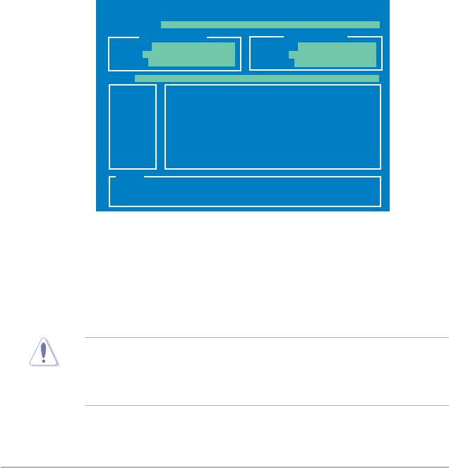
Press <Alt> + <F2> during POST to display the following.
ASUSTek EZ Flash 2 BIOS ROM Utility V3.21
FLASH TYPE: MXIC 25L8005
Current ROM
Update ROM
BOARD: M3N78-EMH HDMI
BOARD: Unknown
VER: 0403 (H:01 B:18)
VER: Unknown
DATE: 03/25/2008
DATE: Unknown
PATH: A:\
A:
Note
[Enter] Select or Load [Tab] Switch [V] Drive Info
[Up/Down/Home/End] Move [B] Backup [Esc] Exit
(2) Enter BIOS setup program. Go to the
Tools menu to select EZ Flash 2
and press <Enter> to enable it.
You can switch between drives by pressing <Tab> before the correct le
is found. Then press <Enter>.
4. When the correct BIOS le is found, EZ Flash 2 performs the BIOS update
process and automatically reboots the system when done.
• This function can support devices such as USB ash disk, or oppy disk
with
FAT 32/16
format only.
• Do not shut down or reset the system while updating the BIOS to prevent
system boot failure!
2-4 Chapter 2: BIOS setup

2.1.3 AFUDOS utility
The AFUDOS utility allows you to update the BIOS le in DOS environment using
a bootable oppy disk with the updated BIOS le. This utility also allows you to
copy the current BIOS le that you can use as backup when the BIOS fails or gets
corrupted during the updating process.
Copying the current BIOS
To copy the current BIOS le using the AFUDOS utility:
• Ensure that the oppy disk is not write-protected and has at least 1024KB
free space to save the le.
• The succeeding BIOS screens are for reference only. The actual BIOS
screen displays may not be same as shown.
1. Copy the AFUDOS utility (afudos.exe) from the motherboard support DVD to
the bootable oppy disk you created earlier.
2. Boot the system in DOS mode, then at the prompt type:
afudos /o[lename]
where the [lename] is any user-assigned lename not more than eight
alphanumeric characters for the main lename and three alphanumeric
characters for the extension name.
A:\>afudos /oOLDBIOS1.rom
Main lename Extension name
3. Press <Enter>. The utility copies the current BIOS le to the oppy disk.
A:\>afudos /oOLDBIOS1.rom
AMI Firmware Update Utility - Version 1.19(ASUS V2.29(03.11.24BB))
Copyright (C) 2002 American Megatrends, Inc. All rights reserved.
Reading ash ..... done
Write to le...... ok
A:\>
The utility returns to the DOS prompt after copying the current BIOS le.
ASUS M3N78-EMH HDMI 2-5

Updating the BIOS le
To update the BIOS le using the AFUDOS utility:
1. Visit the ASUS website (www.asus.com) and download the latest BIOS le for
the motherboard. Save the BIOS le to a bootable oppy disk.
Write the BIOS lename on a piece of paper. You need to type the exact BIOS
lename at the DOS prompt.
2. Copy the AFUDOS utility (afudos.exe) from the motherboard support DVD to
the bootable oppy disk you created earlier.
3. Boot the system in DOS mode, then at the prompt type:
afudos /i[lename]
where [lename] is the latest or the original BIOS le on the bootable oppy disk.
A:\>afudos /iM3NEMHD.ROM
4. The utility veries the le and starts updating the BIOS.
A:\>afudos /iM3NEMHD.ROM
AMI Firmware Update Utility - Version 1.19(ASUS V2.36(03.11.24BB))
Copyright (C) 2002 American Megatrends, Inc. All rights reserved.
WARNING!! Do not turn off power during ash BIOS
Reading le ....... done
Reading ash ...... done
Advance Check ......
Erasing ash ...... done
Writing ash ...... 0x0008CC00 (9%)
Do not shut down or reset the system while updating the BIOS to prevent
system boot failure!
5. The utility returns to the DOS prompt after the BIOS update process is
completed. Reboot the system from the hard disk drive.
A:\>afudos /iM3NEMHD.ROM
AMI Firmware Update Utility - Version 1.19(ASUS V2.36(03.11.24BB))
Copyright (C) 2002 American Megatrends, Inc. All rights reserved.
WARNING!! Do not turn off power during ash BIOS
Reading le ....... done
Reading ash ...... done
Advance Check ......
Erasing ash ...... done
Writing ash ...... done
Verifying ash .... done
Please restart your computer
A:\>
2-6 Chapter 2: BIOS setup

2.1.4 ASUS CrashFree BIOS 3 utility
The ASUS CrashFree BIOS 3 is an auto recovery tool that allows you to restore
the BIOS le when it fails or gets corrupted during the updating process. You can
update a corrupted BIOS le using the motherboard support DVD , the oppy disk
or the USB ash disk that contains the updated BIOS le.
• Prepare the motherboard support DVD, the oppy disk or the USB ash
disk containing the updated motherboard BIOS before using this utility.
• Ensure that you rename the original or updated BIOS le in the oppy disk
or the USB ash disk to M3NEMHD.ROM.
Recovering the BIOS from a oppy disk
To recover the BIOS from a oppy disk:
1. Turn on the system.
2. Insert the oppy disk with the original or updated BIOS le to the oppy disk
drive.
3. The utility displays the following message and automatically checks the
oppy disk for the original or updated BIOS le.
Bad BIOS checksum. Starting BIOS recovery...
Checking for oppy...
When found, the utility reads the BIOS le and starts ashing the corrupted
BIOS le.
Bad BIOS checksum. Starting BIOS recovery...
Checking for oppy...
Floppy found!
Reading le “M3NEMHD.ROM”. Completed.
Start ashing...
DO NOT shut down or reset the system while updating the BIOS! Doing so can
cause system boot failure!
4. Restart the system after the utility completes the updating process.
ASUS M3N78-EMH HDMI 2-7

Recovering the BIOS from the support DVD
To recover the BIOS from the support DVD:
1. Remove any oppy disk from the oppy disk drive, then turn on the system.
2. Insert the support DVD to the optical drive.
3. The utility displays the following message and automatically checks the
oppy disk for the original or updated BIOS le.
Bad BIOS checksum. Starting BIOS recovery...
Checking for oppy...
When no oppy disk is found, the utility automatically checks the optical drive
for the original or updated BIOS le. The utility then updates the corrupted
BIOS le.
Bad BIOS checksum. Starting BIOS recovery...
Checking for oppy...
Floppy not found!
Checking for DVD-ROM...
DVD-ROM found!
Reading le “M3NEMHD.ROM”. Completed.
Start ashing...
4. Restart the system after the utility completes the updating process.
The recovered BIOS may not be the latest BIOS version for this motherboard.
Visit the ASUS website (www.asus.com) to download the latest BIOS le.
Recovering the BIOS from the USB ash disk
To recover the BIOS from the USB ash disk:
1. Insert the USB ash disk that contains BIOS le to the USB port.
2. Turn on the system.
3. The utility will automatically checks the devices for the BIOS le When found,
the utility reads the BIOS le and starts ashing the corrupted BIOS le.
4. Restart the system after the utility completes the updating process.
• Only the USB ash disk with FAT 32/16 format and single partition can
support ASUS CrashFree BIOS 3. The device size should be smaller than
8GB.
• DO NOT shut down or reset the system while updating the BIOS! Doing so
can cause system boot failure!
2-8 Chapter 2: BIOS setup

2.1.5 ASUS Update utility
The ASUS Update is a utility that allows you to manage, save, and update the
®
motherboard BIOS in Windows
environment. The ASUS Update utility allows you
to:
• Save the current BIOS le
• Download the latest BIOS le from the Internet
• Update the BIOS from an updated BIOS le
• Update the BIOS directly from the Internet, and
• View the BIOS version information.
This utility is available in the support DVD that comes with the motherboard
package.
ASUS Update requires an Internet connection either through a network or an
Internet Service Provider (ISP).
Installing ASUS Update
To install ASUS Update:
1. Place the support DVD in the optical drive. The
Drivers menu appears.
2. Click the Utilities tab, then click
Install ASUS Update. See page 3-4 for the
Utilities screen menu.
3. The ASUS Update utility is copied to your system.
®
Quit all Windows
applications before you update the BIOS using this utility.
ASUS M3N78-EMH HDMI 2-9
Updating the BIOS through the Internet
To update the BIOS through the Internet:
®
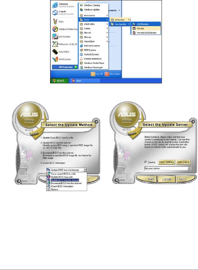
1. Launch the ASUS Update utility from the Windows
desktop by clicking Start
> Programs > ASUS > ASUSUpdate > ASUSUpdate. The ASUS Update
main window appears.
2. Select Update BIOS from
3. Select the ASUS FTP site nearest
the Internet option from the
you to avoid network trafc, or
drop-down menu, then click Next.
click Auto Select. Click Next.
2-10 Chapter 2: BIOS setup

4. From the FTP site, select the BIOS
version that you wish to download.
Click Next.
5. Follow the screen instructions to
complete the update process.
The ASUS Update utility is
capable of updating itself
through the Internet. Always
update the utility to avail all its
features.
Updating the BIOS through a BIOS le
To update the BIOS through a BIOS le:
®
1. Launch the ASUS Update utility from the Windows
desktop by clicking Start
> Programs > ASUS > ASUSUpdate > ASUSUpdate. The ASUS Update
main window appears.
2. Select
Update BIOS from a le
option from the drop-down menu,
then click Next.
3. Locate the BIOS le from the Open
window, then click Open.
4. Follow the screen instructions to
complete the update process.
ASUS M3N78-EMH HDMI 2-11

2.2 BIOS setup program
This motherboard supports a programmable Serial Peripheral Interface (SPI) chip
that you can update using the provided utility described in section “2.1 Managing
and updating your BIOS”.
Use the BIOS Setup program when you are installing a motherboard, reconguring
your system, or prompted to “Run Setup”. This section explains how to congure
your system using this utility.
Even if you are not prompted to use the Setup program, you can change the
conguration of your computer in the future. For example, you can enable the
security password feature or change the power management settings. This
requires you to recongure your system using the BIOS Setup program so that the
computer can recognize these changes and record them in the CMOS RAM of the
SPI chip.
The SPI chip on the motherboard stores the Setup utility. When you start up the
computer, the system provides you with the opportunity to run this program. Press
<Del> during the Power-On Self-Test (POST) to enter the Setup utility. Otherwise,
POST continues with its test routines.
If you wish to enter Setup after POST, reboot the system by doing any of the
following procedures:
• Restart using the OS standard shut-down procedure.
• Press <Ctrl>+<Alt>+<Del> simultaneously.
• Press the reset button on the system chassis.
• Press the power button to turn the system off then back on.
Using the power button, reset button, or the <Ctrl>+<Alt>+<Del> keys to
force reset from a running operating system can cause damage to your data
or system. We recommend to always shut-down the system properly from the
operating system.
The Setup program is designed to make it as easy to use as possible. Being a
menu-driven program, it lets you scroll through the various sub-menus and make
your selections from the available options using the navigation keys.
• The default BIOS settings for this motherboard apply for most conditions
to ensure optimum performance. If the system becomes unstable after
changing any BIOS settings, load the default settings to ensure system
compatibility and stability. Select the Load Default Settings item under the
Exit Menu. See section “2.8 Exit Menu.”
• The BIOS setup screens shown in this section are for reference purposes
only, and may not exactly match what you see on your screen.
• Visit the ASUS website (www.asus.com) to download the latest BIOS le for
this motherboard.
2-12 Chapter 2: BIOS setup
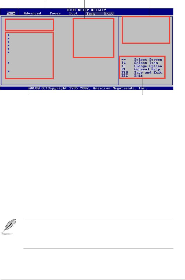
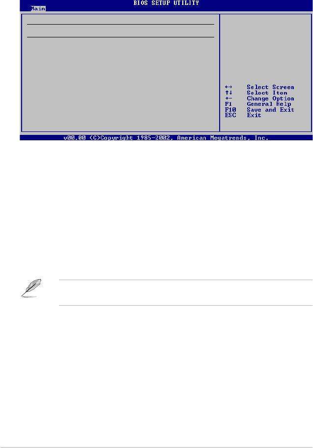
2.2.1 BIOS menu screen
Menu bar Conguration eldsMenu items
General help
Use [ENTER], [TAB]
System Time [00: 19 : 12]
or [SHIFT-TAB] to
System Date [Sun 01/13/2002]
select a eld.
Legacy Diskette A [1.44M,3.5 in.]
Use [+] or [-] to
Primary IDE Master : [Not Detected]
congure system time.
Primary IDE Slave : [Not Detected]
SATA1 : [Not Detected]
SATA2 : [Not Detected]
SATA3 : [Not Detected]
SATA4 : [Not Detected]
IDE Conguration
System Information
Navigation keysSub-menu items
2.2.2 Menu bar
The menu bar on top of the screen has the following main items:
Main For changing the basic system conguration
Advanced For changing the advanced system settings
Power For changing the advanced power management (APM)
conguration
Boot For changing the system boot conguration
Tools For setting EZ Flash 2
Exit For selecting the exit options and loading default
settings
To select an item on the menu bar, press the right or left arrow key on the keyboard
until the desired item is highlighted.
• The BIOS setup screens shown in this chapter are for reference purposes
only, and may not exactly match what you see on your screen.
• Visit the ASUS website (www.asus.com) to download the latest BIOS
information.
ASUS M3N78-EMH HDMI 2-13

Some of the navigation keys differ from one screen to another.
2.2.4 Menu items
The highlighted item on the menu bar displays the specic items for that menu.
For example, selecting Main shows the Main menu items.
The other items (Advanced, Power, Boot, and Exit) on the menu bar have their
respective menu items.
2.2.5 Sub-menu items
A solid triangle before each item on any menu screen means that the iteam has a
sub-menu. To display the sub-menu, select the item and press <Enter>.
2.2.6 Conguration elds
These elds show the values for the menu items. If an item is user-congurable,
you can change the value of the eld opposite the item. You cannot select an item
that is not user-congurable.
A congurable eld is enclosed in brackets, and is highlighted when selected. To
change the value of a eld, select it then press <Enter> to display a list of options.
Refer to “2.2.7 Pop-up window.”
2.2.7 Pop-up window
Select a menu item then press <Enter> to display a pop-up window with the
conguration options for that item.
2.2.8 Scroll bar
A scroll bar appears on the right side of a
menu screen when there are items that do
not t on the screen. Press the
Up/Down arrow keys or <Page Up> /<Page
Down> keys to display the other items on the
screen.
Scroll bar
2.2.9 General help
At the top right corner of the menu screen is a brief description of the selected
item.
2-14 Chapter 2: BIOS setup
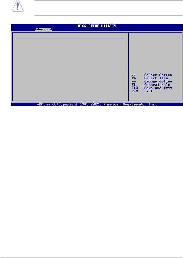
Advanced Chipset settings
WARNING: Setting wrong values in the sections below
may cause system to malfunction.
Configure DRAM Timing by SPD [Enabled]
Memory Acceleration Mode [Auto]
DRAM Idle Timer [Auto]
DRAm Refresh Rate [Auto]
Graphic Adapter Priority [AGP/PCI]
Graphics Aperture Size [ 64 MB]
Spread Spectrum [Enabled]
Select Screen
Select Item
ICH Delayed Transaction [Enabled]
+- Change Option
F1 General Help
MPS Revision [1.4]
F10 Save and Exit
ESC Exit
2.2.3 Navigation keys
At the bottom right corner of a menu screen are the navigation keys for that
particular menu. Use the navigation keys to select items in the menu and change
the settings.
Pop-up window
2.3 Main menu
When you enter the BIOS Setup program, the Main menu screen appears, giving
you an overview of the basic system information.
Refer to section “2.2.1 BIOS menu screen” for information on the menu screen
items and how to navigate through them.
System Time [00:19:13]
Use [ENTER], [TAB]
System Date [Sun 01/13/2002]
or [SHIFT-TAB] to
Legacy Diskette A [1.44M,3.5 in.]
select a eld.
Primary IDE Master :[Not Detected]
Use [+] or [-] to
Primary IDE Slave :[Not Detected]
congure system time.
SATA1 :[ST380011AS]
SATA2 :[Not Detected]
SATA3 :[Not Detected]
SATA4 :[Not Detected]
IDE Conguration
System Information
2.3.1 System Time [xx:xx:xx]
Allows you to set the system time.
2.3.2 System Date [Day xx/xx/xxxx]
Allows you to set the system date.
2.3.3 Legacy Diskette A [1.44M, 3.5 in.]
Sets the type of oppy drive installed. Conguration options: [Disabled] [360K ,
5.25 in.] [1.2M, 5.25 in.] [720K, 3.5 in] [1.44M 3.5 in] [2.88M, 3.5 in]
ASUS M3N78-EMH HDMI 2-15
2.3.4 Primary IDE Master/Slave, SATA1~4
While entering Setup, the BIOS automatically detects the presence of IDE devices.
There is a separate sub-menu for each IDE device. Select a device item then
press <Enter> to display the IDE device information.
Primary IDE Master
Select the type
of device connected
Device : Not Detected
to the system
Type [Auto]
LBA/Large Mode [Auto]
Block (Multi-Sector Transfer) M [Auto]
PIO Mode [Auto]
DMA Mode [Auto]
SMART Monitoring [Auto]
32Bit Data Transfer [Enabled]
The BIOS automatically detects the values opposite the dimmed items (Device,
Vendor, Size, LBA Mode, Block Mode, PIO Mode, Async DMA, Ultra DMA, and
SMART monitoring). These values are not user-congurable. These items show
N/A if no IDE device is installed in the system.
Type [Auto]
Selects the type of IDE drive. Setting to Auto allows automatic selection of the
appropriate IDE device type. Select CDROM if you are specically conguring a
CD-ROM drive. Select ARMD (ATAPI Removable Media Device) if your device
is either a ZIP, LS-120, or MO drive. Conguration options: [Not Installed] [Auto]
[CDROM] [ARMD]
This item does not appear when you select SATA1/SATA2/SATA3/SATA4
devices.
LBA/Large Mode [Auto]
Enables or disables the LBA mode. Setting to Auto enables the LBA mode if the
device supports this mode, and if the device was not previously formatted with LBA
mode disabled. Conguration options: [Disabled] [Auto]
2-16 Chapter 2: BIOS setup

Block (Multi-Sector Transfer) M [Auto]
Enables or disables data multi-sectors transfers. When set to Auto, the data
transfer from and to the device occurs multiple sectors at a time if the device
supports multi-sector transfer feature. When set to [Disabled], the data transfer
from and to the device occurs one sector at a time.
Conguration options: [Disabled] [Auto]
PIO Mode [Auto]
Selects the PIO mode. Conguration options: [Auto] [0] [1] [2] [3] [4]
DMA Mode [Auto]
Selects the DMA mode. Conguration options: [Auto]
SMART Monitoring [Auto]
Enables or disables the S.M.A.R.T. (Self Monitoring and Reporting Technology)
capability of your hard drive. This features allows your system to report read/write
errors of the hard drive and to issue warnings when a third party hardware monitor
utility is installed. Conguration options: [Auto] [Disabled] [Enabled]
32Bit Data Transfer [Enabled]
Enables or disables 32-bit data transfer. Conguration options: [Disabled]
[Enabled]
ASUS M3N78-EMH HDMI 2-17

2.3.5 IDE Conguration
The items in this menu allow you to set or change the congurations for the IDE
devices installed in the system. Select an item then press <Enter> if you wish to
congure the item.
IDE Conguration
Disabled: disables
the integrated IDE
Onboard PCI IDE Controller [Enabled]
Controller.
OnChip S-ATA Controller [Enabled]
Enabled: enable
SATA Mode select [SATA Mode]
the integrated IDE
Controller.
Onboard PCI IDE Controller [Enabled]
Allows you to enable or disable the onboard PCI IDE controller.
Conguration options: [Enabled] [Disabled]
OnChip S-ATA Controller [Enabled]
Allows you to disable or set the OnChip S-ATA devices.
Conguration options: [Enabled] [Disabled]
SATA Mode select [SATA Mode]
Allows you to select the SATA Mode. Conguration options: [SATA Mode] [RAID
Mode] [AHCI Mode]
The following items appears only when the SATA Mode select item is set to
[RAID Mode].
SATA1/2/3/4/5/6 [Enabled]
Allows you to disable or enable the SATA1/2/3/4/5/6.
Conguration options: [Disabled] [Enabled]
2-18 Chapter 2: BIOS setup

2.3.6 System Information
This menu gives you an overview of the general system specications. The BIOS
automatically detects the items in this menu.
AMIBIOS
Version : 0403
Build Date : 03/25/08
Processor
Type : AMD Sempron(tm) Processor 3200+
Speed : 1800MHz
Count : 1
System Memory
Installed Size : 512MB
Usable Size : 384MB
AMI BIOS
Displays the auto-detected BIOS information
Processor
Displays the auto-detected CPU specication
System Memory
Displays the auto-detected system memory
ASUS M3N78-EMH HDMI 2-19
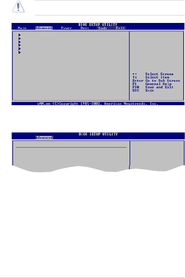
2.4 Advanced menu
The Advanced menu items allow you to change the settings for the CPU and other
system devices.
Take caution when changing the settings of the Advanced menu items. Incorrect
eld values can cause the system to malfunction.
JumperFree Conguration
Adjust System
CPU Conguration
Frequency/Voltage etc.
Chipset
Onboard Devices Conguration
PCIPnP
USB Conguration
2.4.1 JumperFree Conguration
Congure System Frequency/Voltage
Select the target CPU
frequency, and the
AI Overclocking [Auto]
relevant parameters
Memory Voltage [Auto]
will be auto-adjusted.
Frequencies higher
than CPU manufacturer
recommmends are not
AI Overclocking [Auto]
Allows selection of CPU overclocking options to achieve desired CPU internal
frequency. Select either one of the preset overclocking conguration options:
[Auto] - allows you to set overclocking parameters automatically.
[Manual] - allows you to individually set overclocking parameters.
[Standard] - loads the standard settings for the system.
[Overclock Prole] - loads overclocking proles with optimal parameters for stability
when overclocking.
2-20 Chapter 2: BIOS setup

The following two items appear only when the AI Overclocking item is set to
[Manual].
CPU Frequency, MHz [200]
Allows you to enter an integer value to over clock for CPU.
Conguration options: [Min.=200] [Max.=300]
MCP PCI-Express Frequency, MHz [100]
Allows you to enter an integer value to over clock for PCIE.
Conguration options: [Min.=100] [Max.=150]
The following two items appear only when the AI Overclocking item is set to
[Overclock Prole].
Overclock Options [Auto]
Allows you to select the overclock options. Conguration options: [Auto] [Overclock
3%] [Overclock 5%] [Overclock 7%]
Memory Voltage [Auto]
Allows you to adjust the Memory Voltage. Conguration options: [Auto] [1.90V]
[1.95V] [2.00V] [2.05V] [2.10V] [2.15V] [2.20V] [2.25V]
ASUS M3N78-EMH HDMI 2-21

2.4.2 CPU Conguration
CPU Conguration
This option should
Module Version: 13.20
remain disabled for
AGESA Version: 3.1.4.0
the normal operation.
Physical Count: 1
The driver developer
Logical Count: 1
may enable it for
AMD Athlon(tm) Processor 3200+
testing purpose.
Revision: F2
Cache L1: 128KB
Cache L2: 128KB
Cache L3: N/A
Speed : 1800MHz, NB Clk: N/A
Current FSB Multiplier: 9x
Maximum FSB Multiplier: 9x
Able to Change Freq. : Yes
uCode Patch Level : 0x62
GART Error Reporting [Disabled]
Microcode Updation [Enabled]
Secure Virtual Machine Mode [Enabled]
Cool ‘n’ Quite [Enabled]
GART Error Reporting [Disabled]
This option should remain disabled for the normal operation. The driver developer
may enable it for testing purpose. Conguration options: [Disabled] [Enabled]
Microcode Updation [Enabled]
Allows you to enable or disable the microcode updation.
Conguration options: [Disabled] [Enabled]
Secure Virtual Machine Mode [Enabled]
Allows you to enable or disable the AMD Secure Virtual Machine mode.
Conguration options: [Disabled] [Enabled]
Cool ‘n’ Quiet [Enabled]
Allows you to enable or disable the generation of ACPI_PPC, _PSS, and _PCT
objects. Conguration options: [Disabled] [Enabled]
ACPI SRAT Table [Enabled]
Allows you to enable or disable the ACPI SRAT table.
Conguration options: [Disabled] [Enabled]
2-22 Chapter 2: BIOS setup

2.4.3 Chipset
The Chipset menu allows you to change the advanced chipset settings. Select an
item then press <Enter> to display the sub-menu.
Advanced Chipset Setting
Options for NB
WARNING: Setting wrong values in below
sections may cause system to malfunction.
NorthBridge Conguration
Southbridge Conguration
Hyper Transpot Conguraton
NorthBridge Conguration
NorthBridge Chipset Conguration
Memory Conguration
DRAM Conguration
ECC Conguration
Memory Conguration
Memory Conguration
Enable Bank Memory
Interleaving
Bank Interleaving [Auto]
Channel Interleaving [Disabled]
Enable Clock to All DIMMs [Disabled]
MemClk Tristate C3/ATLVID [Disabled]
Memory Hole Remapping [Enabled]
DCT Unganged Mode [Always]
Power Down Enable [Enabled]
Bank Interleaving [Auto]
Allows you to enable the bank memory interleaving.
Conguration options: [Disabled] [Auto]
ASUS M3N78-EMH HDMI 2-23

Channel Interleaving [Disabled]
Allows you to enable the channel memory interleaving.
Conguration options: [Disabled] [Address bits 6] [Address bits 12] [Hash*,
XOR of Address bits [20:16,6] ] [Hash*, XOR of Address bits [20:16,9] ]
Enable Clock to All DIMMs [Disabled]
Enables or disables clock to all DIMMs. Conguration options: [Disabled]
[Enabled]
MemClk Tristate C3/ALTVID [Disabled]
Enables or disables the MemClk Tristate C3/ALTVID.
Conguration options: [Disabled] [Enabled]
Memory Hole Remapping [Enabled]
Enables or disables the memory remapping around memory hole.
Conguration options: [Disabled] [Enabled]
DCT Unganged Mode [Always]
Allow you to enable or disable Unganed mode.
Conguration options: [Auto] [Always]
Power Down Enable [Enabled]
Enables or disables the DDR power down mode.
Conguration options: [Disabled] [Enabled]
DRAM Timing Conguration
DRAM Timing Conguration
Options
Auto
Memory Clock Mode [Auto]
Limit
DRAM Timing Mode [Auto]
Manual
Memory Clock Mode[Auto]
Allows you to set the memoery clock mode. Conguration options: [Auto]
[Limit] [Manual]
DRAM Timing Mode [Auto]
Allows you to set the DRAM timing mode. Conguration options: [Auto] [DCT
0]
2-24 Chapter 2: BIOS setup

ECC Conguration
DRAM ECC allows
ECC Conguration
hardware to report
ECC Mode [Disabled]
and correct memory
DRAM ECC Enable [Disabled]
errors automatically
DRAM SCRUB REDIRECT [Disabled]
maintaining system
4-Bit ECC Mode [Disabled]
integrity.
DRAM BG Scrub [Disabled]
Data Cache BG Scrub [Disabled]
L2 Cache BG Scrub [Disabled]
L3 Cache BG Scrub [Disabled]
ECC Mode [Disabled]
Enables or disables the DRAM ECC that allows the hardware to report and
correct memory errors automatically. Conguration options: [Disabled] [Basic]
[Good] [Super] [Max] [User]
DRAM ECC Enable [Disabled]
Enables or disables the DRAM ECC. Conguration options: [Disabled] [Enabled]
DRAM SCRUB REDIRECT [Disabled]
Enables or disables the DRAM SCRUB REDIRECT feature that allows the system to
correct the DRAM ECC errors immediately when they occur. Conguration options:
[Disabled] [Enabled]
4-Bit ECC Mode [Disabled]
Enables or disables the ECC chip kill feature.
Conguration options: [Disabled] [Enabled]
DRAM BG Scrub [Disabled]
Disables or sets the DRAM BG Scrub. Conguration options: [Disabled] [40ns]
[80ns] [160ns] [320ns] [640ns] [1.28us] [2.56us] [5.12us] [10.2us] [20.5us] [41.0us]
[81.9us] [163.8us] [327.7us] [655.4us]
Data/L2/L3 Cache BG Scrub [Disabled]
Disables or sets the Data/L2/L3 Cache BG Scrub. This item allows the cache RAM
to be corrected when idle. Conguration options: [Disabled] [40ns] [80ns] [160na]
[320ns] [640ns] [1.28us] [2.56us] [5.12us] [10.2us] [20.5us] [41.0us] [81.9us]
[163.8us] [327.7us] [655.4us]
ASUS M3N78-EMH HDMI 2-25

SouthBridge Conguration
SouthBridge chipset Conguration
Options
PCI VGA Card First
Primary Graphics Adapter [PCIE VGA Card Firs]
Internal VGA First
Hybrid SLI Mode [mGPU Auto]
PCIE VGA Card First
Hybrid SLI Frame buffer Size [128MB]
AZALIA Audio [Internal codec+E}
Front Panel Select [HD Audio]
Onboard LAN [Auto]
OnBoard LAN Boot ROM [Disabled]
SouthBridge ACPI HPET TABLE [Enabled]
Primary Graphics Adapter [PCIE VGA Card First]
Display Device Priority, from high to low. Conguration options: [PCIE VGA Card
First] [Internal VGA First] [PCIE VGA Card First]
Hybrid SLI Mode [mGPU Auto]
Allows you to set the Hybrid SLI mode.
Conguration options: [mGPU Auto] [mGPU always enable]
Hybrid SLI Frame buffer Size [128 MB]
Allows you to set the iGPU Frame Buffer Size.
Conguration options: [32 MB] [64 MB] [128 MB] [256 MB]
AZALIA Audio [Internal codec+External codec]
Allows you to set HD Audio mode. Conguration options: [Disabled] [Internal
codec+External codec] [Internal codec] [External codec]
Front Panel Select [HD Audio]
Allows you to set HD Audio mode. Conguration options: [AC97] [HD Audio]
Onboard LAN [Auto]
Allows you to set or disable the Onboard LAN. Conguration options: [Auto]
[Disabled]
OnBoard LAN Boot ROM [Disabled]
Allows you to enable or disable the OnBoard LAN Boot ROM.
Conguration options: [Enabled] [Disabled]
SouthBridge ACPI HPET TABLE [Enabled]
Allows you to enable or disable SouthBridge ACPI HPET TABLE.
Conguration options: [Disabled] [Enabled]
2-26 Chapter 2: BIOS setup

Hyper Transport Conguration
SouthBridge to K8(CPU)
Hyper Transport Conguration
frequency selection
SB to K8(CPU) Freq Auto [Enabled]
by CPU capability
SB to K8(CPU) Freq Auto [Enabled]
Allows you to enable or disable southbridge to K8(CPU) frequency selection by
CPU capability. Conguration options: [Enabled] [Disabled]
The following two items appear only when the SB to K8(CPU) Freq Auto item
is set to [Disabled].
SB to K8(CPU) Frequency [1000 MHz]
Allows you to select southbridge to K8(CPU) frequency. Conguration options:
[200 MHz] [400 MHz] [600 MHz] [800 MHz] [1000 MHz] [1200 MHz] [1400 MHz]
[1600 MHz] [1800 MHz] [2000 MHz] [2200 MHz] [2400 MHz] [2600 MHz]
SB to K8(CPU) LinkWidth [16 16 ]
Allows you to select southbridge to K8(CPU) link width.
Conguration options: [4 4 ] [8 8 ] [16 16 ]
2.4.4 Onboard Devices Conguration
Congure ITE8712 Super IO Chipset
Allows BIOS to select
Serial Port1 Base
Serial Port1 Address [3F8/IRQ4]
Address.
Serial Port1 Mode [Normal]
Parallel Port Address [378]
Parallel Port Mode [Normal]
Serial Port1 Address [3F8/IRQ4]
Allows you to select the Serial Port1 base address.
Conguration options: [Disabled] [3F8/IRQ4][2F8/IRQ3] [3E8/IRQ4] [2E8/IRQ3]
Serial Port1 Mode [Normal]
Allows you to select mode for Serial Port1. Conguration options: [Normal]
[IrDA] [ASK IR]
Parallel Port Address [378]
Allows you to select the Parallel Port base addresses.
Conguration options: [Disabled] [378] [278] [3BC]
Parallel Port Mode [Normal]
Allows you to select the Parallel Port mode. Conguration options: [Normal] [EPP]
[ECP] [EPP+ECP]
ASUS M3N78-EMH HDMI 2-27
2.4.5 PCI PnP
The PCI PnP menu items allow you to change the advanced settings for PCI/PnP
devices. The menu includes setting IRQ and DMA channel resources for either
PCI/PnP or legacy ISA devices, and setting the memory size block for legacy ISA
devices.
Take caution when changing the settings of the PCI PnP menu items. Incorrect
eld values can cause the system to malfunction.
No: lets the BIOS
Advanced PCI/PnP Settings
congure all the
WARNING: Setting wrong values in below sections
devices in the system.
Yes: lets the
may cause system to malfunction.
operating system
congure Plug and Play
Plug And Play O/S [No]
(PnP) devices not
PCI Latency Timer [64]
required for boot if
Allocate IRQ to PCI VGA [Yes]
your system has a Plug
Palette Snooping [Disabled]
and Play operating
system.
IRQ-3 assigned to [PCI Device]
IRQ-4 assigned to [PCI Device]
IRQ-5 assigned to [PCI Device]
IRQ-7 assigned to [PCI Device]
IRQ-9 assigned to [PCI Device]
IRQ-10 assigned to [PCI Device]
IRQ-11 assigned to [PCI Device]
IRQ-14 assigned to [PCI Device]
IRQ-15 assigned to [PCI Device]
Plug and Play O/S [No]
When set to [No], BIOS congures all the devices in the system. When set to
[Yes] and if you install a Plug and Play operating system, the operating system
congures the Plug and Play devices not required for boot.
Conguration options: [No] [Yes]
PCI Latency Timer [64]
Allows you to select the value in units of PCI clocks for the PCI device latency
timer register. Conguration options: [32] [64] [96] [128] [160] [192] [224] [248]
Allocate IRQ to PCI VGA [Yes]
When set to [Yes], BIOS assigns an IRQ to PCI VGA card if the card requests for
an IRQ. When set to [No], BIOS does not assign an IRQ to the PCI VGA card even
if requested. Conguration options: [Yes] [No]
Palette Snooping [Disabled]
When set to [Enabled], the palete snooping feature informs the PCI devices that
an ISA graphics device is installed in the system so that the latter can function
correctly. Conguration options: [Disabled] [Enabled]
2-28 Chapter 2: BIOS setup

IRQ-xx assigned to [PCI Device]
When set to [PCI Device], the specic IRQ is free for use of PCI/PnP devices.
When set to [Reserved], the IRQ is reserved for legacy ISA devices.
Conguration options: [PCI Device] [Reserved]
2.4.6 USB Conguration
The items in this menu allows you to change the USB-related features. Select an
item then press <Enter> to display the conguration options.
USB Conguration
Options
Module Version - 2.24.3-13.4
Enable
Disable
USB Devices Enabled:
None
USB 1.1 Controller [Enabled]
USB 2.0 Controller [Enabled]
Legacy USB Support [Auto]
USB 2.0 Controller Mode [HiSpeed]
The Module Version and USB Devices Enabled items show the
auto-detected values. If no USB device is detected, the item shows None.
USB 1.1 Controller [Enabled]
Enables or disables the USB 1.1 Controller. Conguration options: [Enabled]
[Disabled]
USB 2.0 Controller [Enabled]
Enables or disables the USB 2.0 Controller. Conguration options: [Enabled]
[Disabled]
Legacy USB Support [Enabled]
Allows you to enable or disable support for Legacy USB storage devices, including
USB ash drives and USB hard drives. Setting to Auto allows the system to
detect the presence of USB devices at startup. If detected, the USB controller
legacy mode is enabled. If no USB device is detected, the legacy USB support is
disabled. Conguration options: [Disabled] [Enabled] [Auto]
USB 2.0 Controller Mode [HiSpeed]
Allows you to congure the USB 2.0 controller in HiSpeed (480 Mbps) or Full
Speed (12 Mbps). Conguration options: [Full Speed] [HiSpeed]
ASUS M3N78-EMH HDMI 2-29

2.5 Power menu
The Power menu items allow you to change the settings for the Advanced
Conguration and Power Interface (ACPI) and the Advanced Power Management
(APM). Select an item then press <Enter> to display the conguration options.
Suspend Mode [Auto]
Select the ACPI state
ACPI 2.0 Support [Disabled]
used for System
ACPI APIC support [Enabled]
Suspend.
APM Conguration
Hardware Monitor
2.5.1 Suspend Mode [Auto]
Allows you to select the Advanced Conguration and Power Interface (ACPI) state
to be used for system suspend. Conguration options: [S1 (POS) Only] [S3 Only]
[Auto]
[S1(POS) Only] - Enables the system to enter the ACPI S1 (Power on Suspend)
sleep state. In S1 sleep state, the system appears suspended
and stays in a low power mode. The system can be resumed at
any time.
[S3 Only] - Enables the system to enter the ACPI S3 (Suspend to RAM) sleep
state (default). In S3 sleep state, the system appears to be off
and consumes less power than in the S1 state. When signaled by a
wake-up device or event, the system resumes to its working state
exactly where it was left off.
[Auto] - Detected by OS.
2.5.2 ACPI
2.0 Support [Disabled]
Allows you to add additional tables as per Advanced Conguration and Power
Interface (ACPI) 2.0 specications. Conguration options: [Disabled] [Enabled]
2.5.3 ACPI APIC Support [Enabled]
Allows you to enable or disable the Advanced Conguration and Power Interface
(ACPI) support in the Application-Specic Integrated Circuit (ASIC). When set
to Enabled, the ACPI APIC table pointer is included in the RSDT pointer list.
Conguration options: [Disabled] [Enabled]
2-30 Chapter 2: BIOS setup

2.5.4 APM Conguration
APM Conguration
Options
Restore on AC Power Loss [Power Off]
Power On
Power On By PCI Device [Disabled]
Power Off
Power On By Ring [Disabled]
Last State
Power On By PS/2 KB/MS [Disabled]
Power On By RTC Alarm [Disabled]
Restore on AC Power Loss [Power Off]
When set to Power Off, the system goes into off state after an AC power loss.
When set to Power On, the system goes on after an AC power loss.
Conguration options: [Power On] [Power Off] [Last State]
Power On By PCI Device [Disabled]
When set to [Enabled], this parameter allows you to turn on the system through a
PCI LAN or modem card. This feature requires an ATX power supply that provides
at least 1A on the +5VSB lead. Conguration options: [Disabled] [Enabled]
Power On By Ring [Disabled]
Enable or disable RI to generate a wake event. Conguration options: [Disabled]
[Enabled]
Power On By PS/2 KB/MS [Disabled]
Enable or disable PS/2 Keyboard/Mouse to generate a wake event.
Conguration options: [Disabled] [Enabled]
Power On By RTC Alarm [Disabled]
Allows you to enable or disable RTC to generate a wake event. When this item is
set to Enabled, the items RTC Alarm Date, RTC Alarm Hour, RTC Alarm Minute,
and RTC Alarm Second appear with set values. Conguration options: [Disabled]
[Enabled]
ASUS M3N78-EMH HDMI 2-31

2.5.5 Hardware Monitor
Hardware Monitor
CPU Temperature
CPU Temperature [46ºC/114.5ºF]
MB Temperature [34ºC/93ºF]
CPU Fan Speed [3276RPM]
Chassis Fan Speed [N/A]
VCORE Voltage [ 1.232V]
3.3V Voltage [ 3.328V]
5V Voltage [ 4.915V]
12V Voltage [11.916V]
Smart Q-FAN Function [Disabled]
CPU Temperature [xxxºC/xxxºF]
MB Temperature [xxxºC/xxxºF]
The onboard hardware monitor automatically detects and displays the motherboard
and CPU temperatures. Select Ignored if you do not wish to display the detected
temperatures.
CPU Fan Speed [xxxxRPM] or [Ignored]
The onboard hardware monitor automatically detects and displays the CPU
fan speed in rotations per minute (RPM). If the fan is not connected to the
motherboard, the eld shows N/A. Select Ignored if you do not wish to display the
detected speed.
Chassis Fan Speed [xxxxRPM] or [N/A] or [Ignored]
The onboard hardware monitor automatically detects and displays the chassis fan speed
in rotations per minute (RPM). If the fan is not connected to the chassis, the specic eld
shows N/A. Select Ignored if you do not wish to display the detected speed.
VCORE Voltage, 3.3V Voltage, 5V Voltage, 12V Voltage
The onboard hardware monitor automatically detects the voltage output through
the onboard voltage regulators.
Smart Q-Fan Function [Disabled]
Allows you to enable or disable the ASUS Q-Fan feature that smartly adjusts the
fan speeds for more efcient system operation. Conguration options: [Disabled]
[Enabled]
2-32 Chapter 2: BIOS setup

2.6 Boot menu
The Boot menu items allow you to change the system boot options. Select an item
then press <Enter> to display the sub-menu.
Boot settings
Species the Boot
Device Priority
Boot Device Priority
sequence.
A virtual oopy disk
Boot Settings Conguration
drive (Floppy Drive
Security
B:) may appear when
you set the CD-ROM
drive as the rst
boot device.
ASUS M3N78-EMH HDMI 2-33
Select Screen
Select Item
+- Change Option
F1 General Help
F10 Save and Exit
ESC Exit
2.6.1 Boot Device Priority
Boot Device Priority
Species the boot
sequence from the
1st Boot Device [1st FLOPPY DRIVE]
available devices.
2nd Boot Device [SATA:3M-ST380011AS]
3rd Boot Device [CDROM:PS-PIONEER D]
1st ~ xxth Boot Device [1st Floppy Drive]
These items specify the boot device priority sequence from the available devices.
The number of device items that appears on the screen depends on the number
of devices installed in the system. Conguration options: [xxth Drive] [Hard Drive]
[ATAPI CD-ROM
] [Disabled]

2.6.2 Boot Settings Conguration
2-34 Chapter 2: BIOS setup
Select Screen
Select Item
+- Change Option
F1 General Help
F10 Save and Exit
ESC Exit
Boot Settings Conguration
Allows BIOS to skip
certain tests while
Quick Boot [Enabled]
booting. This will
Full Screen Logo [Enabled]
decrease the time
AddOn ROM Display Mode [Force BIOS]
needed to boot the
Bootup Num-Lock [On]
system.
PS/2 Mouse Support [Auto]
Wait For ‘F1’ If Error [Enabled]
Hit ‘DEL’ Message Display [Enabled]
Interrupt 19 Capture [Disabled]
Quick Boot [Enabled]
Enabling this item allows the BIOS to skip some power on self tests (POST) while
booting to decrease the time needed to boot the system. When set to [Disabled],
BIOS performs all the POST items. Conguration options: [Disabled] [Enabled]
Full Screen Logo [Enabled]
This allows you to enable or disable the full screen logo display feature.
Conguration options: [Disabled] [Enabled]
Set this item to [Enabled] to use the ASUS MyLogo 2™ feature.
Add On ROM Display Mode [Force BIOS]
Sets the display mode for option ROM. Conguration options: [Force BIOS] [Keep
Current]
Bootup Num-Lock [On]
Allows you to select the power-on state for the NumLock.
Conguration options: [Off] [On]
PS/2 Mouse Support [Auto]
Allows you to enable or disable support for PS/2 mouse.
Conguration options: [Disabled] [Enabled] [Auto]
Wait for ‘F1’ If Error [Enabled]
When set to Enabled, the system waits for the F1 key to be pressed when error
occurs. Conguration options: [Disabled] [Enabled]
Hit ‘DEL’ Message Display [Enabled]
When set to Enabled, the system displays the message “Press DEL to run Setup”
during POST. Conguration options: [Disabled] [Enabled]

Interrupt 19 Capture [Disabled]
When set to [Enabled], this function allows the option ROMs to trap Interrupt 19.
Conguration options: [Disabled] [Enabled]
2.6.3 Security
The Security menu items allow you to change the system security settings. Select
an item then press <Enter> to display the conguration options.
If you forget your BIOS password, you can clear clear it by erasing the CMOS
Real Time Clock (RTC) RAM. See section “1.9 Jumpers” for information on how
to erase the RTC RAM.
ASUS M3N78-EMH HDMI 2-35
Select Screen
Select Item
+- Change Option
F1 General Help
F10 Save and Exit
ESC Exit
Security Settings
<Enter> to change
Supervisor Password : Not Installed
password.
User Password : Not Installed
<Enter> again to
disabled password.
Change Supervisor Password
Change User Passward
Change Supervisor Password
Select this item to set or change the supervisor password. The Supervisor
Password item on top of the screen shows the default Not Installed. After you set a
password, this item shows Installed.
To set a Supervisor Password:
1. Select the Change Supervisor Password item and press <Enter>.
2. From the password box, type a password composed of at least six letters
and/or numbers, then press <Enter>.
3. Conrm the password when prompted.
The message “Password Installed” appears after you successfully set your
password.
To change the supervisor password, follow the same steps as in setting a user
password.
To clear the supervisor password, select the Change Supervisor Password then
press <Enter>. The message “Password Uninstalled” appears.
After you have set a supervisor password, the other items appear to allow you to
change other security settings.

User Access Level [Full Access]
This item allows you to select the access restriction to the Setup items.
Conguration options: [No Access] [View Only] [Limited] [Full Access]
No Access prevents user access to the Setup utility.
View Only allows access but does not allow change to any eld.
Limited allows changes only to selected elds, such as Date and Time.
Full Access allows viewing and changing all the elds in the Setup utility.
Change User Password
Select this item to set or change the user password. The User Password item on
top of the screen shows the default Not Installed. After you set a password, this
item shows Installed.
To set a User Password:
1. Select the Change User Password item and press <Enter>.
2. On the password box that appears, type a password composed of at least six
letters and/or numbers, then press <Enter>.
3. Conrm the password when prompted.
The message “Password Installed” appears after you set your password
successfully.
To change the user password, follow the same steps as in setting a user password.
Clear User Password
Select this item to clear the user password.
Password Check [Setup]
When set to [Setup], BIOS checks for user password when accessing the Setup
utility. When set to [Always], BIOS checks for user password both when accessing
Setup and booting the system. Conguration options: [Setup] [Always]
2-36 Chapter 2: BIOS setup
Select Screen
Select Item
+- Change Option
F1 General Help
F10 Save and Exit
ESC Exit
Security Settings
<Enter> to change
password.
Supervisor Password : Installed
<Enter> again to
User Password : Installed
disabled password.
Change Supervisor Password
User Access Level [Full Access]
Change User Password
Clear User Password
Password Check [Setup]
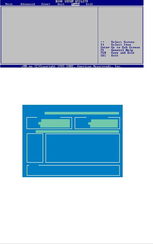
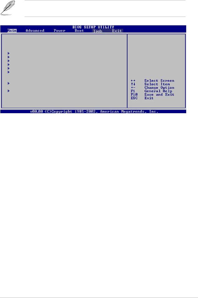
2.7 Tools menu
Press ENTER to run
ASUS EZ Flash 2
the utility to select
and update BIOS.
This utility doesn’t
support:
1. NTFS format
ASUS EZ Flash 2
Allows you to run ASUS EZ Flash 2. When you press <Ok>, a conrmation
message appears. Use the left/right arrow key to select between [Yes] or [No],
then press <Ok> to conrm your choice.
ASUSTek EZ Flash 2 BIOS ROM Utility V3.21
FLASH TYPE: MXIC 25L8005
Current ROM
Update ROM
BOARD: M3N78-EMH HDMI
BOARD: Unknown
VER: 0403 (H:01 B:18)
VER: Unknown
DATE: 03/25/2008
DATE: Unknown
PATH: A:\
A:
Note
[Enter] Select or Load [Tab] Switch [V] Drive Info
[Up/Down/Home/End] Move [B] Backup [Esc] Exit
ASUS M3N78-EMH HDMI 2-37

2.8 Exit menu
The Exit menu items allow you to load the optimal or failsafe default values for the
BIOS items, and save or discard your changes to the BIOS items.
Exit Options
Exit system setup
after saving the
Exit & Save Changes
changes.
Exit & Discard Changes
Discard Changes
F10 key can be used
for this operation.
Load Setup Defaults
Pressing <Esc> does not immediately exit this menu. Select one of the options
from this menu or <F10> from the legend bar to exit.
Exit & Save Changes
Once you are nished making your selections, choose this option from the Exit
menu to ensure the values you selected are saved to the CMOS RAM. An onboard
backup battery sustains the CMOS RAM so it stays on even when the PC is turned
off. When you select this option, a conrmation window appears. Select OK to save
changes and exit.
If you attempt to exit the Setup program without saving your changes, the
program prompts you with a message asking if you want to save your changes
before exiting. Press <Enter> to save the changes while exiting.
Exit & Discard Changes
Select this option only if you do not want to save the changes that you made to
the Setup program. If you made changes to elds other than System Date, System
Time, and Password, the BIOS asks for a conrmation before exiting.
Discard Changes
This option allows you to discard the selections you made and restore the
previously saved values. After selecting this option, a conrmation appears. Select
OK to discard any changes and load the previously saved values.
Load Setup Defaults
This option allows you to load the default values for each of the parameters on the
Setup menus. When you select this option or if you press <F5>, a conrmation
window appears. Select OK to load default values. Select Exit & Save Changes
or make other changes before saving the values to the non-volatile RAM.
2-38 Chapter 2: BIOS setup
Оглавление
- Product
- BIOS setup
- Software
- NVIDIA technology
