Asus V2-PE3: инструкция
Раздел: Бытовая, кухонная техника, электроника и оборудование
Тип: Компьютер
Инструкция к Компьютеру Asus V2-PE3
English
Vintage V2-PE3
Barebone System
Quick Installation Guide
2 Quick installation guide
English
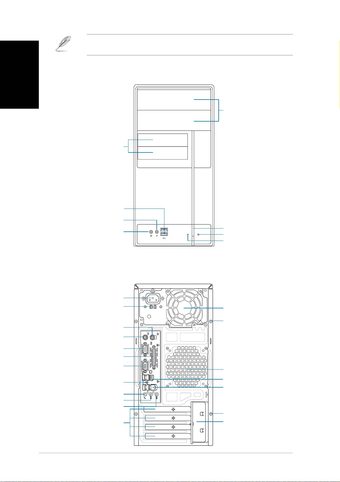
Front panel features
Rear panel features
Quick installation guide
5.25-inch drive
5.25-inch drive
bay cover
bay cover
Power button
Power button
Reset button
Reset button
HDD LED
HDD LED
USB 2.0 ports
USB 2.0 ports
Microphone port
Microphone port
3.5-inch drive bay
3.5-inch drive bay
cover
cover
Headphone port
Headphone port
PS/2 mouse port
PS/2 mouse port
Cover screw
Cover screw
PS/2 keyboard port
PS/2 keyboard port
Parallel port
Parallel port
Line In port
Line In port
Voltage selector
Voltage selector
Metal bracket lock
Metal bracket lock
Power connector
Power connector
Serial port
Serial port
VGA port
VGA port
USB 2.0 ports
USB 2.0 ports
Line Out port
Line Out port
Microphone port
Microphone port
Expansion slot
Expansion slot
metal brackets
metal brackets
Power supply fan
Power supply fan
Chassis fan vents
Chassis fan vents
LAN (RJ-45) port
LAN (RJ-45) port
Cover screw
Refer to the system user guide for installation details and other system
information from ASUS website.
1394
Cover screw
IEEE 1394 port
IEEE 1394 port
3Quick installation guide
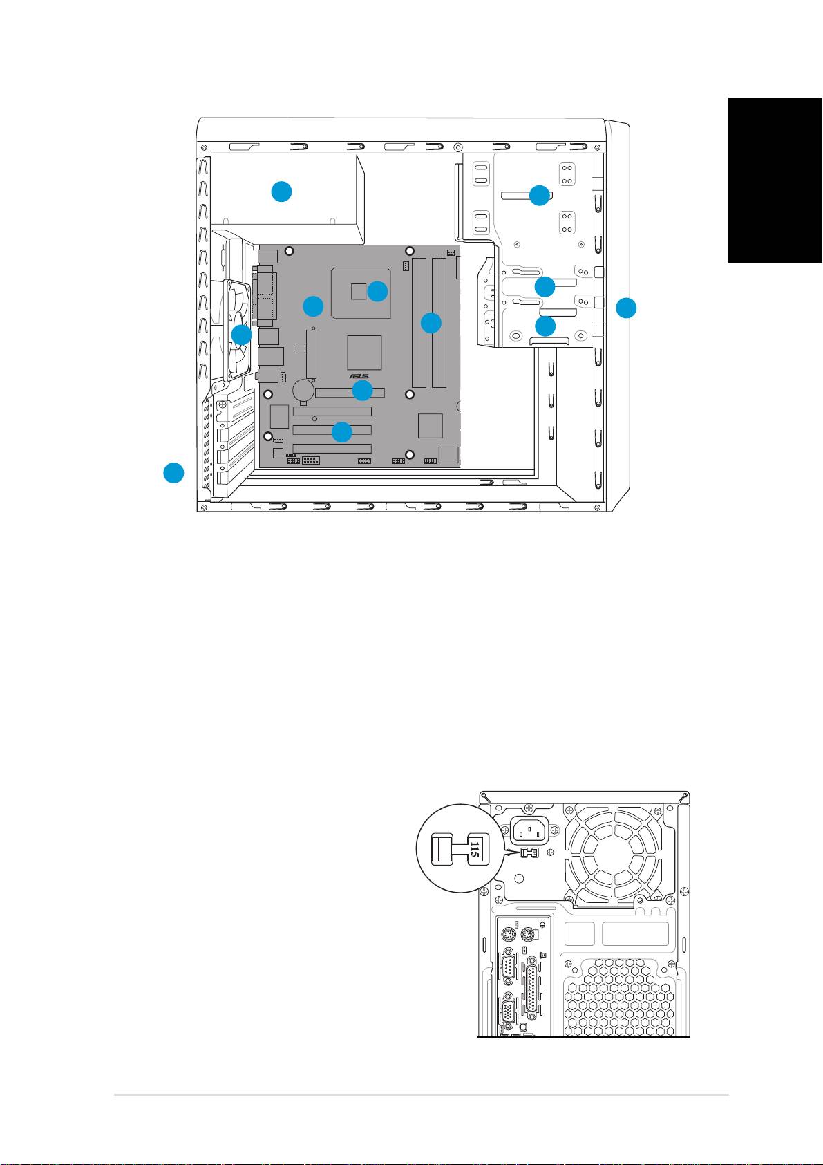
Internal components
English
1. Front panel cover
8. ASUS motherboard
2. 5.25-inch optical drive bays
9. Chassis fan
3. Hard disk drive bay
10. AGP slot
4. Floppy disk drive bay
11. PCI slots
5. Power supply unit
12. Metal bracket lock
6. CPU socket
7. DIMM sockets
Selecting the voltage
The systemʼs power supply unit has
a 115 V/230 V voltage selector
switch located beside the power
connector. Use this switch to select
the appropriate system input voltage
according to the voltage supply in your
area.
If the voltage supply in your area is
100-127 V, set the switch to 115 V.
If the voltage supply in your area is
200-240 V, set the switch to 230 V.
Quick installation guide
5
2
3
1
4
9
®
6
7
12
12
8
10
10
11
11
4 Quick installation guide
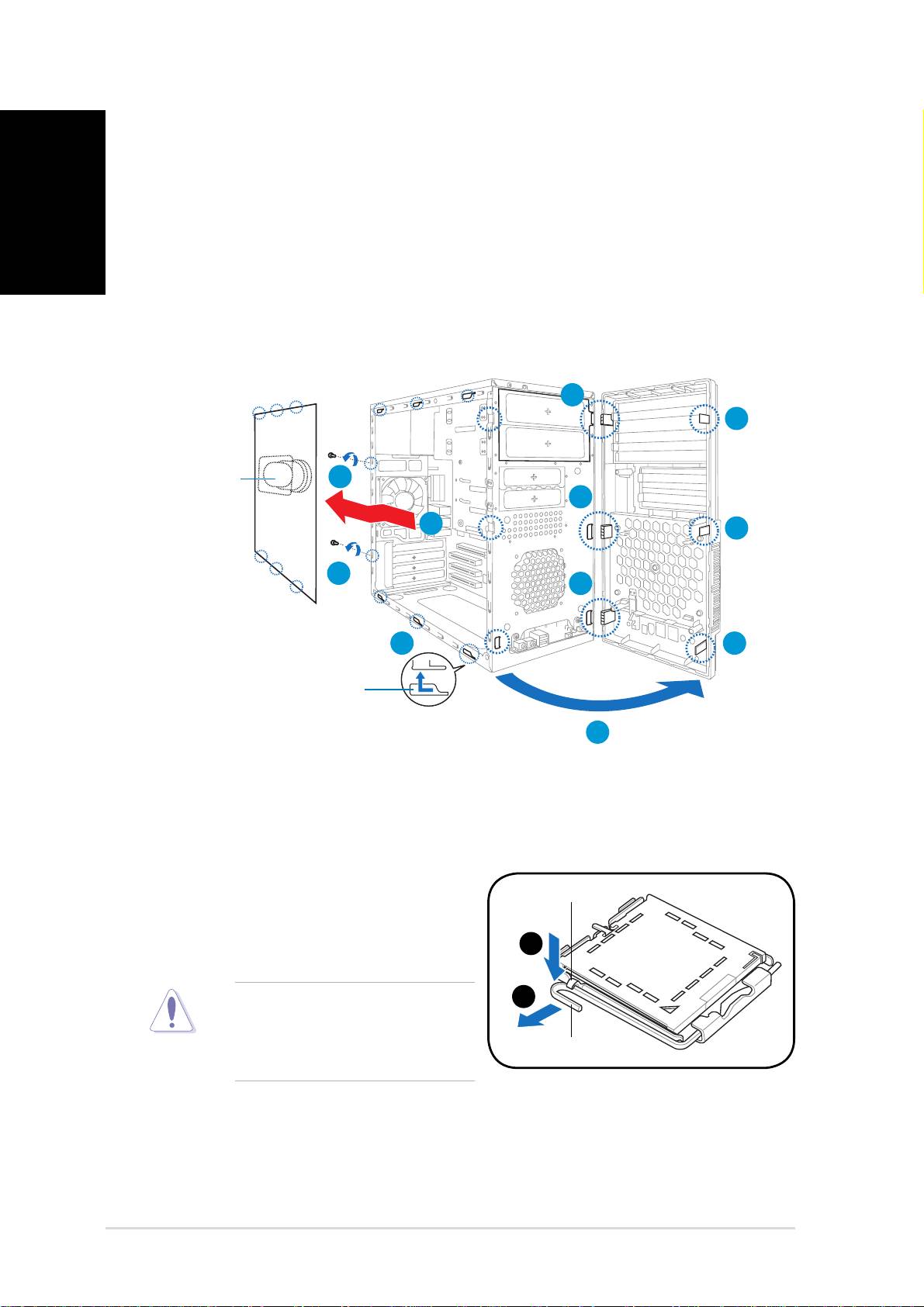
Removing the side cover and
front panel assembly
English
1. Remove the cover screws on the rear panel.
2. Pull the side cover toward the rear panel until its hooks disengage
from the chassis tabs. Set the side cover aside.
3. Locate the front panel assembly hooks, then lift them until they
disengage from the chassis.
4. Swing the front panel assembly to the right, until the hinge-like tabs
on the right side of the assembly are exposed.
5. Remove the front panel assembly, then set aside.
Installing a CPU
To install a CPU:
1. Locate the CPU socket on the motherboard.
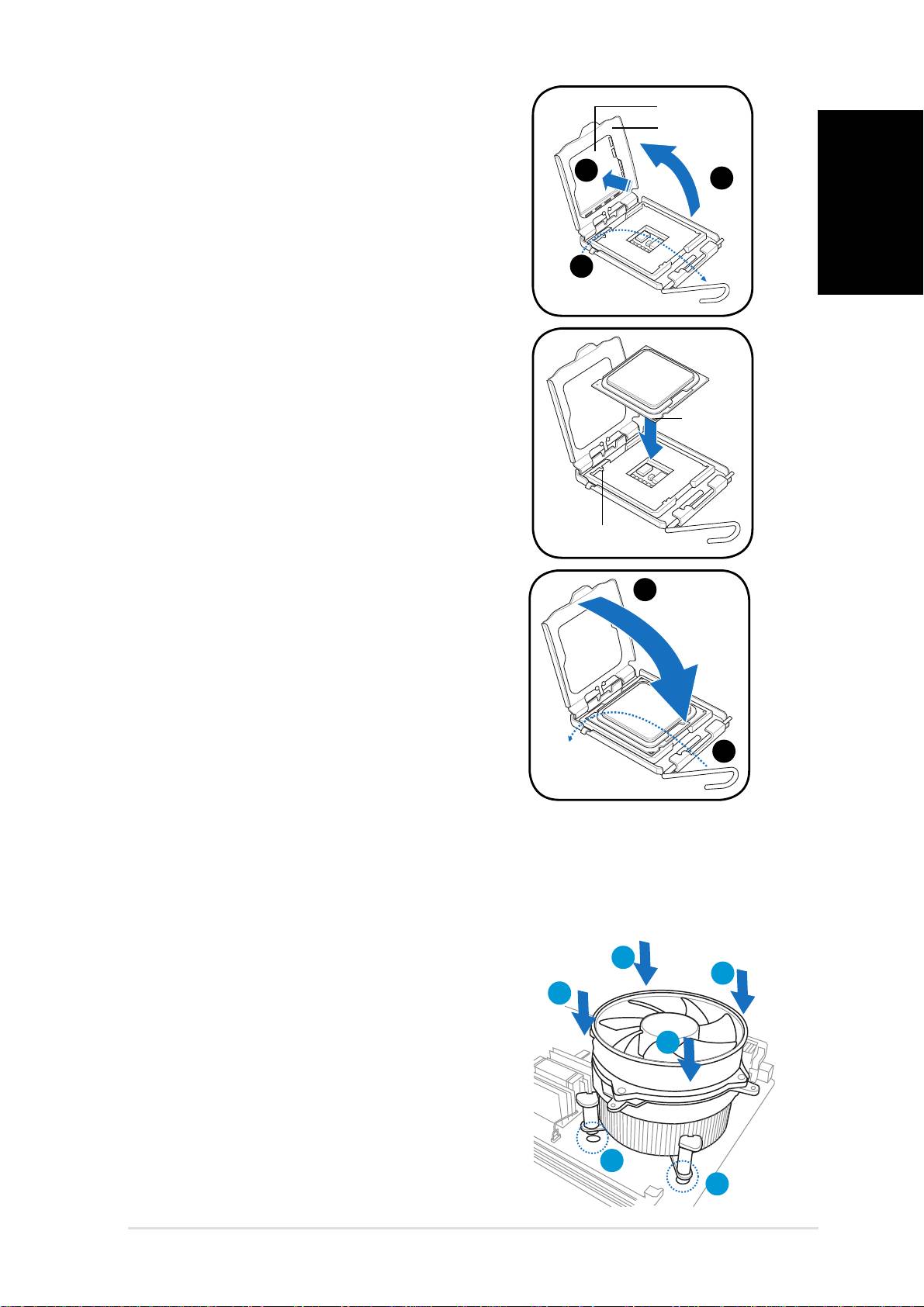
2. Press the load lever with your
thumb (A), then move it to the
left (B) until it is released from
the retention tab.
To prevent damage to the
socket pins, do not remove
the PnP cap unless you are
installing a CPU.
Quick installation guide
A
A
B
B
Load lever
Load lever
Retention tab
Retention tab
4
Air duct
1
Air duct
3
4
2
3
1
4
2
3
Chassis tab holes
4
Chassis tab holes
4
5Quick installation guide
3. Lift the load lever in the direction of
the arrow to a 135º angle.
4. Lift the load plate with your thumb
and forefi nger to a 100º angle (4A),
then push the PnP cap from the load
plate window to remove (4B).
English
5. Position the CPU over the socket,
making sure that the gold triangle
is on the bottom-left corner of the
socket. Fit the socket alignment key
into the CPU notch.
6. Close the load plate (A), then push
the load lever (B) until it snaps into
the retention tab.
Installing the CPU fan and heatsink assembly
®
®
The Intel
Pentium
4 LGA775 processor requires a specially designed
heatsink and fan assembly to ensure optimum thermal condition and
performance.
To install the CPU heatsink and fan:
1. Place the heatsink on top of the installed
CPU, making sure that the four fasteners
match the holes on the motherboard.
2. Push down two fasteners at a time
in a diagonal sequence to secure the
heatsink and fan assembly in place.
3. When the fan and heatsink assembly is in
place, connect the CPU fan cable to the
connector on the motherboard.
Quick installation guide
3
A
B
B
A
1
1
3
4A
4A
4B
4B
Load plate
Load plate
PnP cap
PnP cap
Gold
Gold
triangle
triangle
mark
mark
Alignment key
Alignment key
A
A
B
B
6 Quick installation guide
Installing a DIMM
English
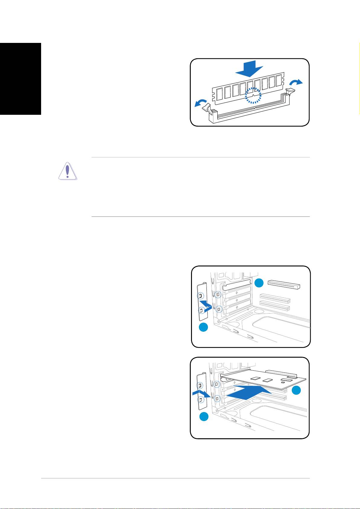
1. Locate the DIMM sockets in the
motherboard.
2. Unlock a DIMM socket by
pressing the retaining clips
outward.
3. Align a DIMM on the socket such
that the notch on the DIMM
matches the break on the socket.
4. Push the DIMM to the socket until the retaining clips snap inward.
• Unplug the power supply before adding or removing DIMMs.
Failure to do so may cause damage to the motherboard and/or
components.
• A DDR2 DIMM is keyed with a notch so that it fi ts in only one
direction. Do not force a DIMM into a socket to avoid damaging the
DIMM.
Installing an expansion card
1. Remove the metal bracket lock.
2. Remove the metal cover opposite
the slot that you intend to use.
3. Insert the card connector to the
slot, then press the card fi rmly
until it fi ts in place.
4. Replace the metal bracket lock.
Quick installation guide
3
4
4
2
1
7Quick installation guide
Installing storage drives
English
Quick installation guide
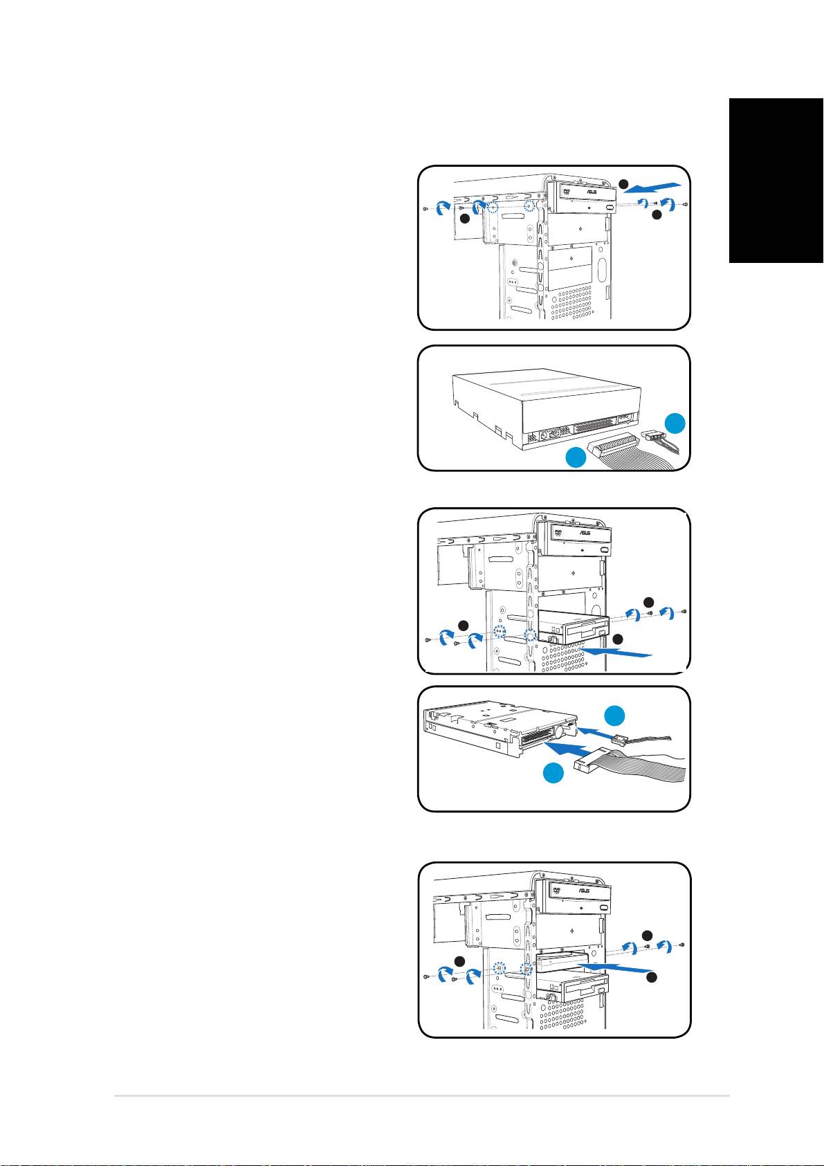
Optical drive
Optical drive
2
1. Place the chassis upright, then
remove the upper 5.25” drive
3
3
bay metal plate cover.
2. Insert the optical drive to the
bay, then carefully push the
drive until its screw holes align
with the holes on the bay.
3. Secure the optical drive with two
screws on both sides of the bay.
4. Connect the IDE (A) and power
(B) plugs to connectors at the
back of the drive.
Floppy disk drive
Floppy disk drive
1. Place the chassis upright, then
remove the lower 3.5” drive bay
metal plate cover.
3
2. Insert the fl oppy disk drive to
the bay, then carefully push the
3
2
drive until its screw holes align
with the holes on the bay.
3. Secure the fl oppy disk drive with
two screws on both sides of the
bay.
4. Connect the signal (A) and
power (B) plugs to connectors at
the back of the drive.
B
A
Hard disk drive
Hard disk drive
1. Place the chassis upright, then
remove the upper 3.5” drive bay
metal plate cover.
3
2. Insert the hard disk drive to the
3
bay, then carefully push the
2
drive until its screw holes align
with the holes on the bay.
3. Secure the hard disk drive with
two screws on both sides of the
bay.
B
A
B
8 Quick installation guide
4.
English
Quick installation guide
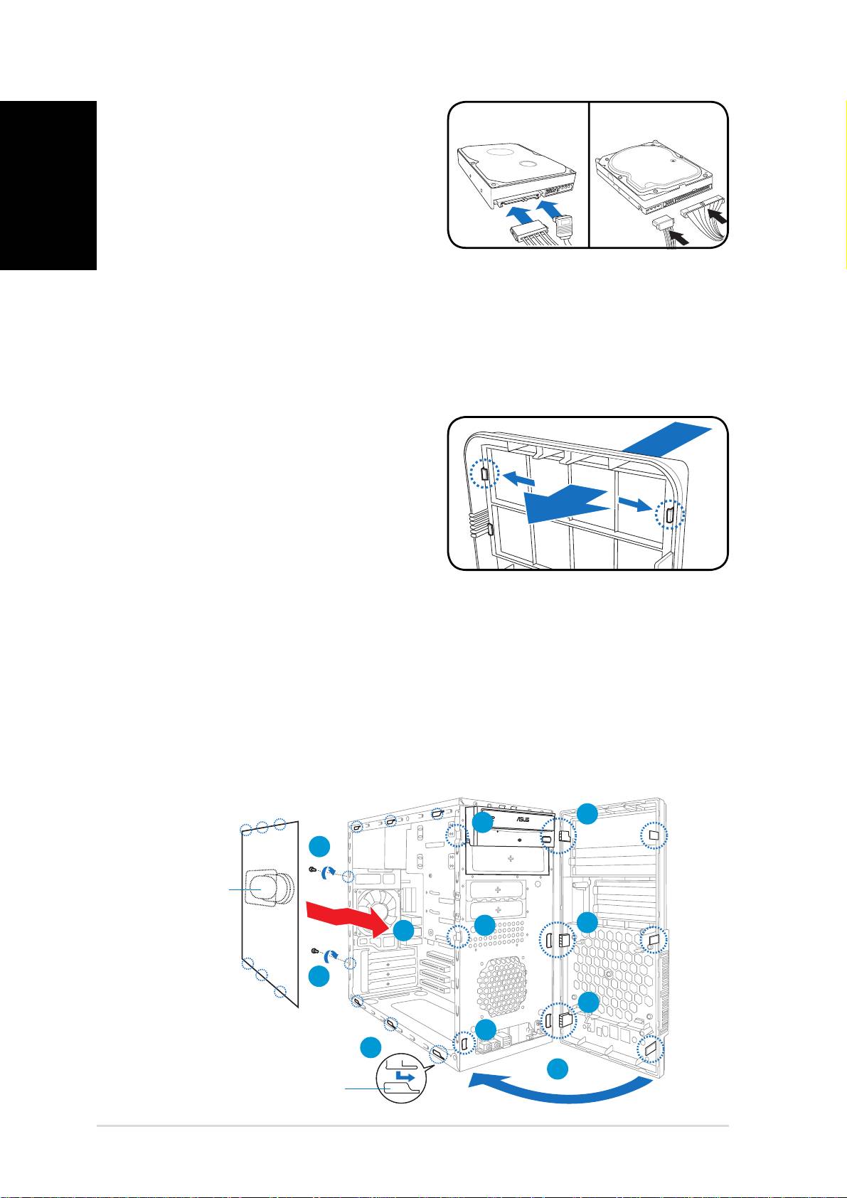
For SATA HDD
For SATA HDD: Connect the SATA
signal and power plugs to the
connectors at the back of the
drive.
For IDE HDD
For IDE HDD: Connect the IDE signal
and power plugs to the connectors
at the back of the drive.
SATA IDE
SATA IDE
Removing the bay covers and reinstalling the
front panel assembly and side cover
If you installed an optical and/or fl oppy disk drive, remove the bay cover(s)
on the front panel assembly before reinstalling it to the chassis. To do this:
1. Locate the bay cover locks.
2. Press the locks outward to
release the bay cover.
3. Push the bay cover inward, then
set it aside.
4. Follow the same instructions to
remove the 3.5” drive bay cover.
To reinstall the front panel assembly and side cover:
1. Insert the front panel assembly hinge-like tabs to the holes on the
right side of the chassis.
2. Swing the front panel assembly to the left, then insert the hooks to
the chassis until the front panel assembly fi ts in place.
3. Insert the side cover hooks to the chassis top and bottom holes.
4. Push the side cover to the direction of the front panel until it fi ts in place.
5. Secure the cover with two screws you removed earlier.
5
Air duct
Air duct
1
2
2
1
4
5
1
2
3
2
Chassis tab holes
Chassis tab holes
