Asus A7V8X: инструкция
Раздел: Компьютерная техника, комплектующие, аксессуары
Тип: Материнская Плата
Инструкция к Материнской Плате Asus A7V8X

A7V8X
User Guide
Motherboard

E1119
Checklist
Second Edition
September 2002
Copyright © 2002 ASUSTeK COMPUTER INC. All Rights Reserved.
No part of this manual, including the products and software described in it, may be
reproduced, transmitted, transcribed, stored in a retrieval system, or translated into any
language in any form or by any means, except documentation kept by the purchaser for
backup purposes, without the express written permission of ASUSTeK COMPUTER INC.
(“ASUS”).
Product warranty or service will not be extended if: (1) the product is repaired, modified or
altered, unless such repair, modification of alteration is authorized in writing by ASUS; or (2)
the serial number of the product is defaced or missing.
ASUS PROVIDES THIS MANUAL “AS IS” WITHOUT WARRANTY OF ANY KIND, EITHER
EXPRESS OR IMPLIED, INCLUDING BUT NOT LIMITED TO THE IMPLIED WARRANTIES
OR CONDITIONS OF MERCHANTABILITY OR FITNESS FOR A PARTICULAR PURPOSE.
IN NO EVENT SHALL ASUS, ITS DIRECTORS, OFFICERS, EMPLOYEES OR AGENTS BE
LIABLE FOR ANY INDIRECT, SPECIAL, INCIDENTAL, OR CONSEQUENTIAL DAMAGES
(INCLUDING DAMAGES FOR LOSS OF PROFITS, LOSS OF BUSINESS, LOSS OF USE
OR DATA, INTERRUPTION OF BUSINESS AND THE LIKE), EVEN IF ASUS HAS BEEN
ADVISED OF THE POSSIBILITY OF SUCH DAMAGES ARISING FROM ANY DEFECT OR
ERROR IN THIS MANUAL OR PRODUCT.
SPECIFICATIONS AND INFORMATION CONTAINED IN THIS MANUAL ARE FURNISHED
FOR INFORMATIONAL USE ONLY, AND ARE SUBJECT TO CHANGE AT ANY TIME
WITHOUT NOTICE, AND SHOULD NOT BE CONSTRUED AS A COMMITMENT BY ASUS.
ASUS ASSUMES NO RESPONSIBILITY OR LIABILITY FOR ANY ERRORS OR
INACCURACIES THAT MAY APPEAR IN THIS MANUAL, INCLUDING THE PRODUCTS
AND SOFTWARE DESCRIBED IN IT.
Products and corporate names appearing in this manual may or may not be registered
trademarks or copyrights of their respective companies, and are used only for identification or
explanation and to the owners’ benefit, without intent to infringe.
ii

Contents
FCC/CDC statements.....................................................................vi
Safety information ......................................................................... vii
About this guide............................................................................ viii
Features
How this guide is organized ................................................ viii
Conventions used in this guide .............................................ix
Where to find more information .............................................ix
ASUS contact information ...............................................................x
A7V8X specifications summary......................................................xi
Chapter 1: Product introduction
1.1 Welcome! ........................................................................... 1-1
1.2 Package contents............................................................... 1-1
1.3 Special features.................................................................. 1-2
1.3.1 Product highlights .................................................. 1-2
1.4 Motherboard overview........................................................ 1-6
1.4.1 Major components ................................................. 1-6
1.4.2 Core specifications ................................................ 1-8
Chapter 2: Hardware information
2.1 Motherboard installation ..................................................... 2-1
2.1.1 Placement direction ............................................... 2-1
2.1.2 Screw holes ........................................................... 2-1
2.2 Motherboard layout ............................................................ 2-2
2.3 Before you proceed ............................................................ 2-3
2.4 Central Processing Unit (CPU)........................................... 2-4
2.4.1 Overview ................................................................ 2-4
2.4.2 Installing the CPU .................................................. 2-5
2.5 System memory ................................................................. 2-6
2.5.1 Overview ................................................................ 2-6
2.5.2 Memory configurations .......................................... 2-7
2.5.3 Qualified Vendor List.............................................. 2-7
2.5.4 Installing a DIMM ................................................... 2-8
2.5.5 Removing a DIMM ................................................. 2-9
2.6 Expansion slots .................................................................2-11
2.6.1 Installing an expansion card..............................................2-11
2.6.2 Configuring an expansion card..........................................2-11
iii

Contents
Safeguards
2.6.3 PCI slots .............................................................. 2-13
2.6.4 AGP slot............................................................... 2-13
2.7 Switches and jumpers ...................................................... 2-14
2.8 Connectors ....................................................................... 2-17
Chapter 3: Powering up
3.1 Starting up for the first time ................................................ 3-1
3.2 Vocal POST Messages ...................................................... 3-2
3.3 Powering off the computer ................................................. 3-4
Chapter 4: BIOS setup
4.1 Managing and updating your BIOS .................................... 4-1
4.1.1 Using ASUS EZ Flash to update the BIOS ............ 4-1
4.1.2 Using AFLASH to update the BIOS ....................... 4-3
4.2 BIOS Setup program .......................................................... 4-7
4.2.1 BIOS menu bar ...................................................... 4-8
4.2.2 Legend bar............................................................. 4-8
4.3 Main Menu........................................................................ 4-10
4.3.1 Primary and Secondary Master/Slave ................. 4-12
4.3.2 Keyboard Features .............................................. 4-16
4.4 Advanced Menu ............................................................... 4-17
4.4.1 Chip Configuration ............................................... 4-20
4.4.2 I/O Device Configuration...................................... 4-23
4.4.3 PCI Configuration ................................................ 4-25
4.5 Power Menu ..................................................................... 4-29
4.5.1 Power Up Control ................................................ 4-29
4.5.2 Hardware Monitor ................................................ 4-31
4.6 Boot Menu ........................................................................ 4-33
4.7 Exit Menu ......................................................................... 4-35
Chapter 5: Software support
5.1 Install an operating system................................................. 5-1
5.2 Support CD information...................................................... 5-1
iv

Contents
5.2.1 Running the support CD ........................................ 5-1
5.2.2 Drivers menu ......................................................... 5-2
5.2.3 Utilities menu ......................................................... 5-3
5.2.4 ASUS Contact Information..................................... 5-6
5.2.5 Other information ................................................... 5-7
5.3 Software information .......................................................... 5-9
5.3.1 ASUS Update ........................................................ 5-9
5.3.2 ASUS MyLogo2™................................................ 5-10
5.3.3 ASUS PC Probe .................................................. 5-12
5.3.4 E-Color 3Deep ..................................................... 5-17
5.3.5 Winbond Voice Editor .......................................... 5-20
5.3.6 Multi-Channel Audio Feature ............................... 5-24
5.4 Using the Promise Chip for RAID 0 or 1........................... 5-26
5.4.1 Installing the Hard Disks ...................................... 5-27
™
5.4.2 Enter FastTrak376
BIOS and FastBuild Utility... 5-28
5.4.3 Creating a RAID 0 Array ...................................... 5-29
5.4.4 Creating a RAID 1 Array ...................................... 5-30
5.4.5 Other FastBuild Utility Commands....................... 5-32
5.5 Manual Installation of IDE/RAID Drivers .......................... 5-34
®
™
5.5.1 Win9x-ME Promise
FastTrak376
Driver........... 5-34
®
™
5.5.2 Win2000 / XP Promise
FastTrak376
Driver ..... 5-34
®
™
5.5.3 Win NT Promise
FastTrak376
Driver ............... 5-35
®
™
5.5.4 Installing the Promise
FastTrak376
Driver in a New Windows 2000 / XP System ....... 5-35
Index ........................................................................................ I-1
v
FCC/CDC statements
Federal Communications Commission Statement
This device complies with FCC Rules Part 15. Operation is subject to the
following two conditions:
• This device may not cause harmful interference, and
• This device must accept any interference received including interference
that may cause undesired operation.
This equipment has been tested and found to comply with the limits for a
Class B digital device, pursuant to Part 15 of the FCC Rules. These limits
are designed to provide reasonable protection against harmful interference
in a residential installation. This equipment generates, uses and can radiate
radio frequency energy and, if not installed and used in accordance with
manufacturer’s instructions, may cause harmful interference to radio
communications. However, there is no guarantee that interference will not
occur in a particular installation. If this equipment does cause harmful
interference to radio or television reception, which can be determined by
turning the equipment off and on, the user is encouraged to try to correct the
interference by one or more of the following measures:
• Reorient or relocate the receiving antenna.
• Increase the separation between the equipment and receiver.
• Connect the equipment to an outlet on a circuit different from that to
which the receiver is connected.
• Consult the dealer or an experienced radio/TV technician for help.
The use of shielded cables for connection of the monitor to the
graphics card is required to assure compliance with FCC regulations.
Changes or modifications to this unit not expressly approved by the
party responsible for compliance could void the user’s authority to
operate this equipment.
Canadian Department of Communications Statement
This digital apparatus does not exceed the Class B limits for radio noise
emissions from digital apparatus set out in the Radio Interference
Regulations of the Canadian Department of Communications.
This class B digital apparatus complies with Canadian ICES-003.
vi

Safety information
Electrical safety
• To prevent electrical shock hazard, disconnect the power cable from
the electrical outlet before relocating the system.
• When adding or removing devices to or from the system, ensure that
the power cables for the devices are unplugged before the signal
cables are connected. If possible, disconnect all power cables from the
existing system before you add a device.
• Before connecting or removing signal cables from the motherboard,
ensure that all power cables are unplugged.
• Seek professional assistance before using an adpater or extension
cord. These devices could interrupt the grounding circuit.
• Make sure that your power supply is set to the correct voltage in your
area. If you are not sure about the voltage of the electrical outlet you
are using, contact your local power company.
• If the power supply is broken, do not try to fix it by yourself. Contact a
qualified service technician or your retailer.
Operation safety
• Before installing the motherboard and adding devices on it, carefully
read all the manuals that came with the package.
• Before using the product, make sure all cables are correctly connected
and the power cables are not damaged. If you detect any damage,
contact your dealer immediately.
• To avoid short circuits, keep paper clips, screws, and staples away from
connectors, slots, sockets and circuitry.
• Avoid dust, humidity, and temperature extremes. Do not place the
product in any area where it may become wet.
• Place the product on a stable surface.
• If you encounter technical problems with the product, contact a
qualified service technician or your retailer.
vii

About this guide
This user guide contains the information you need when installing the
ASUS A7V8X motherboard.
How this guide is organized
This manual contains the following parts:
• Chapter 1: Product introduction
This chapter describes the features of the A7V8X motherboard. It
includes brief descriptions of the special attributes of the motherboard
and the new technology it supports.
• Chapter 2: Hardware information
This chapter lists the hardware setup procedures that you have to
perform when installing system components. It includes description of
the switches, jumpers, and connectors on the motherboard.
• Chapter 3: Powering up
This chapter describes the power up sequence and gives information
on the BIOS beep codes.
• Chapter 4: BIOS setup
This chapter tells how to change system settings through the BIOS
Setup menus. Detailed descriptions of the BIOS parameters are also
provided.
• Chapter 5: Software support
This chapter describes the contents of the support CD that comes with
the motherboard package.
• Index
This part contains an alphabetical list of the topics found in this
document.
viii

Conventions used in this guide
To make sure that you perform certain tasks properly, take note of the
following symbols used throughout this manual.
DANGER/WARNING: Information to prevent injury to yourself
when trying to complete a task.
CAUTION: Information to prevent damage to the components
when trying to complete a task.
IMPORTANT: Information that you MUST follow to complete a
task.
NOTE: Tips and additional information to aid in completing a task.
Where to find more information
Refer to the following sources for additional information and for product
and software updates.
1. ASUS Websites
The ASUS websites worldwide provide updated information on ASUS
hardware and software products. The ASUS websites are listed in the
ASUS Contact Information on page x.
2. Optional Documentation
Your product package may include optional documentation, such as
warranty flyers, that may have been added by your dealer. These
documents are not part of the standard package.
ix

ASUS contact information
ASUSTeK COMPUTER INC. (Asia-Pacific)
Address: 150 Li-Te Road, Peitou, Taipei, Taiwan 112
General Tel: +886-2-2894-3447
General Fax: +886-2-2894-3449
General Email: info@asus.com.tw
Technical Support
MB/Others (Tel): +886-2-2890-7121 (English)
Notebook (Tel): +886-2-2890-7122 (English)
Desktop/Server (Tel): +886-2-2890-7123 (English)
Support Fax: +886-2-2890-7698
Support Email: tsd@asus.com.tw
Web Site: www.asus.com.tw
Newsgroup: cscnews.asus.com.tw
ASUS COMPUTER INTERNATIONAL (America)
Address: 6737 Mowry Avenue, Mowry Business Center,
Building 2, Newark, CA 94560, USA
General Fax: +1-510-608-4555
General Email: tmd1@asus.com
Technical Support
Support Fax: +1-510-608-4555
General Support: +1-502-995-0883
Web Site: www.asus.com
Support Email: tsd@asus.com
ASUS COMPUTER GmbH (Europe)
Address: Harkortstr. 25, 40880 Ratingen, BRD, Germany
General Fax: +49-2102-442066
General Email: sales@asuscom.de (for marketing requests only)
Technical Support
Support Hotline: MB/Others: +49-2102-9599-0
Notebook (Tel): +49-2102-9599-10
Support Fax: +49-2102-9599-11
Support (Email): www.asuscom.de/de/support (for online support)
Web Site: www.asuscom.de
x

A7V8X specifications summary
CPU
Socket A for AMD Thoroughbred, Athlon XP/Athlon/Duron
600 MHz ~ 2.4 GHz+
Chipset
Northbridge: VIA KT400
Southbridge: VIA VT8235
Front Side Bus (FSB)
333/266/200Mhz
Memory
3 x DDR DIMM Sockets
Maximum 3 GB unbuffered PC2100/1600 non-ECC SDRAM
Memory.(Note: PC2700 maximum to 2 DIMM support only.
PC3200 maximum to 1 DIMM support only.)
Visit the ASUS website for the latest qualified DDR400/DDR333 module list
Expansion slots
1 x AGP 8X
6 x PCI (one shared with ASUS BlueMagic PCI slot.)
IDE
2 x UltraDMA 133/100/66
Flexible Serial ATA
Promise controller supports one ATA133 channel and two
(optional)
Serial ATA connectors
RAID (optional)
RAID 0 supported by two or three Parallel ATA or Serial ATA
connectors. RAID 1 supported by two Parallel or Serial ATA
connectors.
Audio (optional)
Realtek 6-channel CODEC
S/PDIF in/out interface
LAN (optional)
Broadcom 10/100 Mbps or 1 Gbps Ethernet controller
USB 2.0
VT8235 built-in USB 2.0
6 x USB 2.0 port
IEEE 1394 (optional)
VIA 1394 controller
2 x 1394 port
Special Features
ASUS POST Reporter (optional)
ASUS MyLogo2
ASUS EZ Flash
ASUS Q-Fan
Multi-language BIOS
Power Loss Restart
ASUS Jumperfree
SFS (Stepless Frequency Selection)
support S/PDIF in/out interface (on audio model only)
ASUS C.O.P. (CPU Overheating Protection)
AGP Warning LED
(continued on the next page)
xi

A7V8X specifications summary
Back Panel I/O Ports
1 x Parallel
2 x Serial
1 x PS/2 Keyboard
1 x PS/2 Mouse
1 x Audio I/O (on audio model only)
4 x USB 2.0
1 x RJ-45 Port (on LAN model only)
Internal I/O
CPU/Power/Chassis FAN connectors
Connectors
20 pin ATX power connector
IDE LED connector
Chassis Intrusion, SM Bus, SIR
Smart Card reader connector
Front panel audio connector (on audio model only)
Game port
S/PDIF in/out connector (on audio model only)
CD/AUX/Modem audio in (on audio model only)
2 x 1394 port (on 1394 model only)
1 x USB 2.0 connector supports additional 2 USB 2.0 ports
2 x Serial ATA port (on serial ATA model only)
BIOS features
4Mb Flash ROM, Award BIOS, TCAV, PnP, DMI2.0, WfM2.0,
SM BIOS2.3, Multi-language BIOS, ASUS EZ Flash, ASUS
MyLogo2
Industry standard
PCI 2.2, USB 2.0
Manageability
WfM 2.0. DMI 2.0, chassis intrusion, SMBus
Form Factor
ATX form factor: 12 in x 9.6 in (30.5 cm x 24.5 cm)
Support CD contents
Device drivers
ASUS PC Probe
tm
Trend Micro
PC-cillin 2002 anti-virus software
ASUS LiveUpdate Utility
InterVideo WinCinema [WinDVD/WinRip/WinCorder/
WinProducer] software (optional)
Accessories
User’s manual
Support CD
2 x UltraDMA 133/100/66 cable
IDE cable
FDD cable
I/O shield
2-port USB 2.0/ Game port module
2-port IEEE 1394 module (on 1394 model only)
2 x IEEE 1394 cable (on 1394 model only)
2 x Serial ATA cable (on Serial ATA model only)
* Specifications are subject to change without notice.
xii
Chapter 1
This chapter describes the features of the
ASUS A7V8X motherboard. It includes brief
explanations of the special attributes of the
motherboard and the new technology it
supports.
Product introduction

Chapter summary
1.1 Welcome! ........................................................ 1-1
1.2 Package contents .......................................... 1-1
1.3 Special features ............................................. 1-2
1.4 Motherboard overview................................... 1-6
ASUS A7V8X motherboard

1.1 Welcome!
®
Thank you for buying the ASUS
A7V8X motherboard!
The ASUS A7V8X motherboard is loaded with the most advanced
technologies to deliver the maximum performance for socket A processors.
Based on the advanced VIA KT400 chipset with DDR 400 support, the
ASUS A7V8X also features AGP 8X, serial ATA, USB 2.0 as well as
optional 6-channel audio, Gigabit LAN and 1394. Unique ASUS features
such as ASUS C.O.P., Q-Fan and MyLogo2 and more are included to
ensure the best user experience and value in a motherboard.
Before you start installing the motherboard, and hardware devices on it,
check the items in your package with the list below.
1.2 Package contents
Check your ASUS A7V8X package for the following items.
ASUS A7V8X motherboard
ATX form factor: 12 in x 9.6 in (30.5 cm x 24.5 cm)
ASUS A7V8X series support CD
ASUS 2-port USB 2.0/ GAME port module
ASUS 2-port IEEE 1394 module (on 1394 model only)
ASUS S/PDIF in/out module (on audio model only)
2 pcs. 1394 cable (on 1394 model only)
2 pcs. Serial ATA cable (on Serial ATA model only)
2 pcs. 80-conductor ribbon cable for UltraDMA/66/100/133 IDE drives
40-conductor IDE cable
Ribbon cable for a 3.5-inch floppy drive
I/O shield
Bag of extra jumper caps
User Guide
Quick Setup Guide and Reference Card (retail box only)
Jumpers and Connectors Sticker (retail box only)
If any of the above items is damaged or missing, contact your retailer.
ASUS A7V8X motherboard user guide
1-1

1.3 Special features
1.3.1 Product highlights
333MHz FSB Athlon XP CPU support
AMD’s Athlon XP 2700+ and all follow-up CPUs now support 333MHz
Front Side Bus (FSB) for increased application program productivity and
enhanced digital media experience.
AGP 8X support
AGP 8X (AGP 3.0) is the next generation VGA interface specification that
enables enhanced graphics performance with high bandwidth speeds up
to 2.12 GB/s. With a bus of 533Mhz, AGP 8X is twice as fast as AGP 4X.
Serial ATA technology (optional)
Serial ATA is the next generation ATA specification that provides scalable
performance for today and tomorrow. With up to 150MB/s data transfer
rate, Serial ATA is faster than current Parallel ATA, while providing 100%
software compatibility.
DDR400 (PC3200) support
DDR400 (PC3200), the latest and fastest DDR memory standard, supports
bandwidth up to 3.2 GB/s to provide enhanced system performance.
(Note: PC2700 maximum to 2 DIMM support only. PC3200 maximum to 1 DIMM
support only.)
Gigabit LAN (optional)
The A7V8X with BroadCom Gigabit LAN, delivers transfer speeds up to
ten times faster than conventional 10/100 Ethernet connections. Gigabit
LAN is the networking standard for the future and is ideal for handling
large amounts of data such as video, audio and voice.
USB 2.0 technology
USB 2.0 is the latest connectivity standard for next generation components
and peripherals. USB 2.0 delivers fast transfer speeds up to 40 times
faster at 480 MB/s, for easy connectivity and ultra-fast data transfers. The
higher bandwidth of USB 2.0 allows connection of devices such as high
resolution video conferencing cameras, next generation scanners, printers,
and fast storage units. USB 2.0 is backward compatible with USB 1.1.
1-2
Chapter 1: Product introduction

IEEE 1394 support (optional)
IEEE 1394 interface provides high speed digital interface for audio / video
appliances such as digital television, digital video camcorders, storage
peripherals & other PC portable devices.
ASUS Q-Fan feature
The ASUS Q-Fan technology smartly adjusts the fan speeds according to
the system loading to ensure quiet, cool, and efficient operation. See
details on page 4-32.
C.O.P. (CPU Overheating Protection):
®
™
With AMD
Athlon XP
installed, the motherboard offers automatic CPU
Overheating Protection to prolong the life of the entire system. If the CPU
temperature exceeds the set criteria, the PC shuts down automatically.
ASUS POST Reporter™ (optional)
A7V8X offers a new exciting feature called the ASUS POST Reporter™ to
provide friendly voice messages and alerts during the Power-On Self-Tests
(POST). Through the system’s internal speaker, or an added external
speaker, you will hear the messages informing you of the system boot
status and causes of boot errors, if any. The bundled Winbond Voice
Editor software allows you to customize the voice messages, and provides
multi-language support.
ASUS MyLogo2™
This new feature present in the A7V8X motherboard allows you to
personalize and add style to your system with customizable boot logos.
ASUS Multi-language BIOS
The multi-language BIOS allows you to select the language of your choice
from the available options. The localized BIOS menus allow you to
configure easier and faster. Visit the ASUS website for information on the
supported languages. See page 4-11 on how to select your desired
language.
ASUS A7V8X motherboard user guide
1-3

ASUS EZ Flash BIOS
With the ASUS EZ Flash, you can easily update the system BIOS even
before loading the operating system. No need to use a DOS-based utility
or boot from a floppy disk.
6-channel Audio (optional)
The A7V8X uses an onboard Realtek CODEC that lets you enjoy high-
quality 6-channel audio without having to buy advanced sound cards.
InterVideo WinCinema Software (on Gold version only)
A full array of bundled software is now available with ASUS motherboards!
Submerge yourself in ahole new multimedia experience.
WinDVD: the world’s most popular DVD software supporting 5.1-channel
audio
WinRip: MP3 Player/Encoder/Ripper featuring virtual 5.1-channel and
surround sound effects.
WinCoder: Real-time MPEG-1 & 2 software video encoder.
WinProducer: Easy-of-use MPEG-1 & 2 video editing software.
1-4
Chapter 1: Product introduction

ASUS A7V8X motherboard user guide
1-5
1.4 Motherboard overview
Before you install the A7V8X motherboard, familiarize yourself with its
physical configuration and available features to facilitate the motherboard
installation and future upgrades. A sufficient knowledge of the motherboard
specifications will also help you avoid mistakes that may damage the
board and its components.
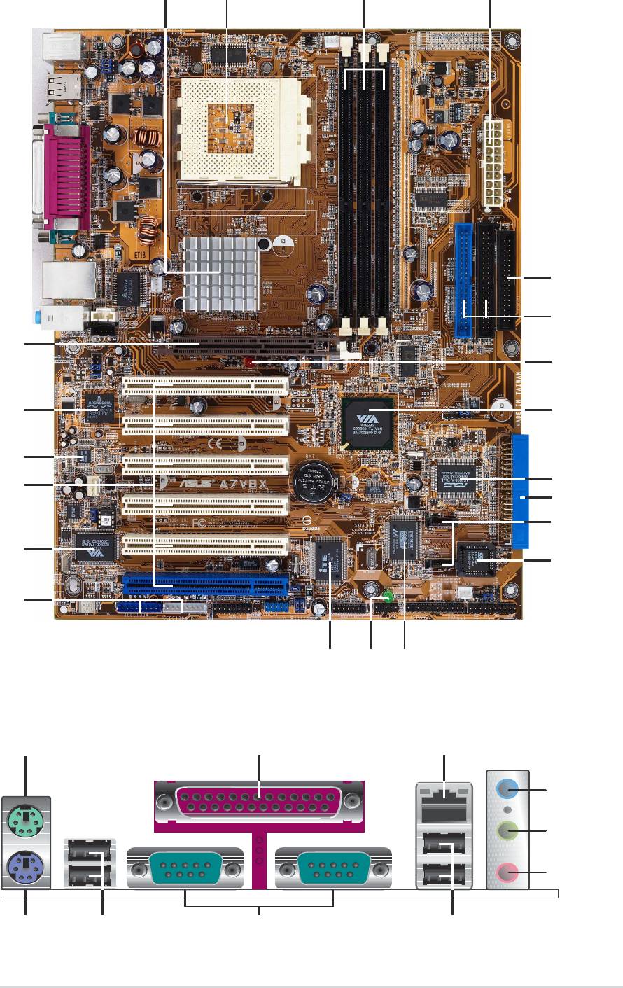
1.4.1 Major components
The following are the major components of the A7V8X motherboard as
pointed out in the picture on page 1-7.
A
1. North Bridge controller
19. Audio CODEC
L
2. CPU socket
20. 10/100 or 1Gbit LAN controller
3. DDR DIMM sockets
21. AGP slot
4. ATX power connector
22. Mouse port
5. Floppy disk connector
23. Parallel port
L
6. IDE connectors
24. RJ-45 port
A
7. AGP warning LED
25. Line In jack
A
8. South Bridge controller
26. Line Out jack
A
9. ASUS ASIC
27. Microphone jack
10. RAID IDE connector*
28. USB 2.0 ports 3 and 4
11. SATA connectors*
29. Serial ports 1 and 2
12. Flash ROM
30. USB 2.0 ports 1 and 2
13. SATA controller*
31. Keyboard port
14. Stand-by LED
15. Super I/O controller
* - on SATA model only
E
E
16 IEEE 1394 connector
- on IEEE model only
E
L
17. IEEE 1394 controller
- on LAN model only
A
18. PCI slots
- on Audio model only
(Note: The ASUS BlueMagic
PCI slot works as a normal
PCI slot and it is also compatible
with the ASUS proprietary
wireless card - Spacelink B&W)
See page 1-8 for the specifications of each major component. Refer to
Chapter 2 for detailed information on the components.
1-6
Chapter 1: Product introduction
1
243
5
6
21
7
20
8
19
9
18
10
11
17
12
16
15
14 13
22
23 24
25
26
27
31 30 29
28
ASUS A7V8X motherboard user guide
1-7
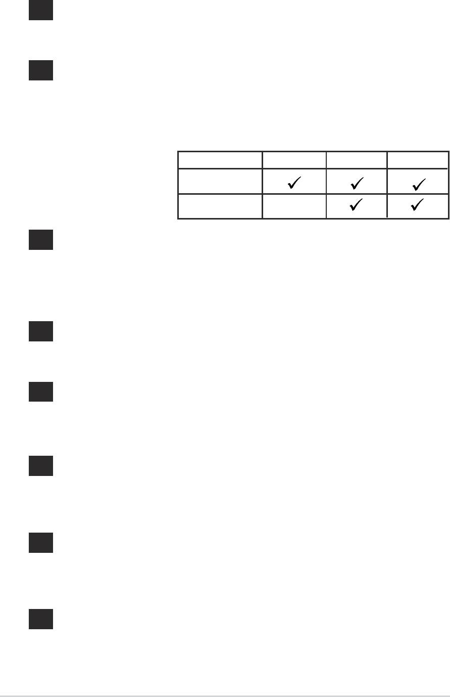
1.4.2 Core specifications
®
North bridge controller. The VIA
KT400 supports AGP 8X mode,
1
266/200MHz Front Side Bus, and the latest 400/333/266/200MHz
64-bit memory bus.
CPU socket. Socket 462 (Socket A) surface mount, Zero Insertion
2
Force (ZIF) socket for the AMD Athlon XP/Athlon/Duron
Processors, with 600 MHz ~ 2.4GHz system bus. (Note: When
using 333MHz FSB CPU, system memory supports DDR333 or
DDR400 only.)
TABLE 1.4.2
FSB DDR 266 DDR 333 DDR 400
FSB/DDR
Support Table
200/266 MHz
333 MHz
DDR DIMM sockets. These three 184-pin DIMM sockets support up
3
to 3GB system memory using unbuffered non-ECC PC2100/1600
DDR DIMMs.(Note: PC2700 maximum to 2 DIMM support only.
PC3200 maximum to 1 DIMM support only.)
Visit the ASUS website (www.asus.com) for the latest qualified DDR400 module list.
ATX power connector. This 20-pin connector connects to an ATX
4
+12V power supply. The power supply must have at least 1A on the
+5V standby lead (+5VSB).
Floppy disk connector. This connector accommodates the
5
provided ribbon cable for the floppy disk drive. One side of the
connector is slotted to prevent incorrect insertion of the floppy disk
cable.
IDE connectors. These dual-channel bus master IDE connectors
6
support up to four Ultra DMA133/100/66, PIO Modes 3 & 4 IDE
devices. Both the primary (blue) and secondary (black) connectors
are slotted to prevent incorrect insertion of the IDE ribbon cable.
AGP warning LED. Serving as a smart burn-out protection for the
7
motherboard, this red LED lights up if you plug in any 3.3V AGP
card into the AGP slot. When this LED is lit, there is no way you
can turn on the system power even if you press the power button.
®
South bridge controller. The VIA
VT8235 integrated peripheral
8
controller supports various I/O functions including, 2-channel ATA/
133 bus master IDE controller, up to six USB 2.0 ports, LPC Super
I/O interface, AC’97 interface and PCI 2.2 interface.
1-8
Chapter 1: Product introduction

ASUS ASIC. This chip performs multiple system functions that
9
include hardware and system voltage monitoring among others.
RAID IDE connector. This one-channel connector supports Ultra
10
ATA133/100/66 hard disk drivers in RAID 0 or RAID 1
configurations. (on SATA model only)
SATA connectors. This connector accomodates the provided
11
Serial ATA cable. One side of the connector is slotted to prevent
incorrect insertion of the cable. The Serial ATA is an evolutionary
replacement for the Parallel ATA. (on SATA model only)
12
Flash ROM. This 4Mb firmware contains the programmable BIOS
program.
SATA controller. The Promise controller supports one ATA133
13
channel and two Serial ATA connectors. (on SATA model only)
Standby power LED. This LED lights up if there is a standby
14
power on the motherboard. This LED acts as a reminder to turn off
the system power before plugging or unplugging devices.
Super I/O controller. This Low Pin Count (LPC) interface provides
15
the commonly used Super I/O functionality. The chipset supports a
high-performance floppy disk controller for a 360K/720K/1.44M/
2.88M floppy disk drive, a multi-mode parallel port, two standard
compatible UARTs, a Standard Infrared (SIR), a Smart Card
Reader and a Flash ROM interface.
IEEE 1394 connectors. This connectors accomodate the bundled
16
two (2) IEEE 1394 cables. (on 1394 model only)
IEEE 1394 controller. This high speed serial bus provides
17
enhanced PC connectivity for Audio and Video, high-speed
peripheral devices for storage and other portable devices.
(on 1394 model only)
PCI slots. These six 32-bit PCI 2.2 expansion slots support bus
18
master PCI cards like SCSI or LAN cards with 133MB/s maximum
throughput. (Note: The ASUS BlueMagic PCI slot works as a
normal PCI slot and it is also compatible with the ASUS proprietary
wireless card - Spacelink B&W)
Audio CODEC . The Realtek ALC650 is an AC’97 compliant audio
19
CODEC for PC multimedia systems. (on audio models only)
ASUS A7V8X motherboard user guide
1-9

Gigabit LAN or LAN controller. The BroadCom Gigabit LAN
20
delivers transfer rates up to ten times faster than conventional 10/
100 Ethernet connections. Ideal for handling large amounts of data
such as video, audio and voice. (on LAN models only)
AGP slot. This Accelerated Graphics Port (AGP) slot supports 1.5V
21
AGP8X mode graphics cards for 3D graphical applications.
PS/2 mouse port. This green 6-pin connector is for a PS/2 mouse.
22
Parallel port. This 25-pin port connects a parallel printer, a
23
scanner, or other devices.
RJ-45 port. This port allows connection to a Local Area Network
24
(LAN) through a network hub. (on LAN models only)
Line In jack. This Line In (light blue) jack connects a tape player or
25
other audio sources. In 6-channel mode, the function of this jack
becomes Line Out/Front Speaker Out. (on audio models only)
Line Out jack. This Line Out (lime) jack connects a headphone or
26
a speaker. In 6-channel mode, the function of this jack becomes
Front Speaker Out. (on audio models only)
Microphone jack. This Mic (pink) jack connects a microphone. In
27
6-channel mode, the function of this jack becomes Center Speaker
Out/Subwoofer. (on audio models only)
USB 2.0 ports 3 and 4. These two 4-pin Universal Serial Bus
28
(USB) ports are available for connecting USB 2.0 devices.
Serial ports 1 and 2. This 9-pin COM1/COM2 ports are for
29
pointing devices or other serial devices.
USB 2.0 ports 1 and 2. These two 4-pin Universal Serial Bus
30
(USB) ports are available for connecting USB 2.0 devices.
PS/2 keyboard port. This purple 6-pin connector is for a PS/2
31
keyboard.
1-10
Chapter 1: Product introduction
