Asus A7V8X: Chapter 3
Chapter 3: Asus A7V8X
Chapter 3
This chapter describes the power up
sequence and gives information on the
BIOS beep codes.
Powering up

Chapter summary
3.1 Starting up for the first time.......................... 3-1
3.2 Vocal POST Messages................................... 3-2
3.3 Powering off the computer ........................... 3-4
ASUS A7V8X motherboard
3.1 Starting up for the first time
1. After making all the connections, replace the system case cover.
2. Be sure that all switches are off.
3. Connect the power cord to the power connector at the back of the system
chassis.
4. Connect the power cord to a power outlet that is equipped with a surge
protector.
5. Turn on the devices in the following order:
a. Monitor
b. External SCSI devices (starting with the last device on the chain)
c. System power (if you are using an ATX power supply, you need to
switch on the power supply as well as press the ATX power switch on
the front of the chassis).
6. After applying power, the power LED on the system front panel case lights
up. For ATX power supplies, the system LED lights up when you press the
ATX power switch. If your monitor complies with “green” standards or if it
has a “power standby” feature, the monitor LED may light up or switch
between orange and green after the system LED turns on. The system
then runs the power-on tests. While the tests are running, the BIOS beeps
or additional messages appear on the screen. If you do not see anything
within 30 seconds from the time you turned on the power, the system may
have failed a power-on test. Check the jumper settings and connections or
call your retailer for assistance.
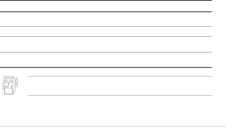
Award BIOS Beep Codes
Beep Meaning
One short beep when No error during POST
displaying logo
Long beeps in an endless loop No DRAM installed or detected
One long beep followed by Video card not found or video card
three short beeps memory bad
High frequency beeps when CPU overheated;
system is working System running at a lower frequency
You will not hear the BIOS beeps when the ASUS POST Reporter™ is
enabled. You will hear the vocal POST messages instead.
7. At power on, hold down <Delete> to enter BIOS Setup. Follow the
instructions in Chapter 4.
ASUS A7V8X motherboard user guide
3-1

3.2 Vocal POST Messages
This motherboard includes the Winbond speech controller to support a
special feature called the ASUS POST Reporter™. This feature gives you
vocal POST messages and alerts to inform you of system events and boot
status. In case of a boot failure, you will hear the specific cause of the
problem.
These POST messages are customizable using the Winbond Voice Editor
software that came with your package. You can record your own
messages to replace the default messages.
Following is a list of the default POST messages and their corresponding
actions, if any.
POST Message Action
No CPU installed • Install an AMD Thoroughbred/Athlon
XP/Athlon/ Duron Processor
into the CPU socket.
System failed CPU test • Check the CPU if properly installed.
• Call ASUS technical support for
assistance. See the “ASUS contact
information” on page x.
System failed memory test • Install 184-pin unbuffered
PC3200/2700/2100/1600 DIMMs
into the DIMM sockets.
• Check if the DIMMs on the DIMM
sockets are properly installed.
• Make sure that your DIMMs are
not defective.
• Refer to section “2.5 System
memory” for instruction on installing
a DIMM.
System failed VGA test • Install a PCI VGA card into one of
the PCI slots, or an AGP card
into the AGP slot.
• Make sure that your VGA/AGP card
is not defective.
System failed due to CPU • Check your CPU settings in BIOS
over-clocking and make sure you only set to the
recommended settings. See section
“4.4Advanced menu.”
3-2
Chapter 3: Powering up
POST Message Action
No keyboard detected • Check your keyboard if properly
connected to the purple PS/2
connector on the rear panel.
• See section “1.4.1 Major
components” for the location of the
connector.
No floppy disk detected • Make sure you have connected a
floppy disk to the floppy disk
connector on the motherboard.
• See section “2.8 Connectors.”
No IDE hard disk detected • Make sure you have connected an
IDE hard disk drive to the one of the
IDE connectors on the motherboard.
• See section “2.8 Connectors.”
CPU temperature too high • Check CPU fan if working properly.
CPU fan failed • Check the CPU fan and make sure
it turns on after you applied power
to the system.
CPU voltage out of range • Check your power supply and
make sure it is not defective.
• Call ASUS technical support for
assistance. See the “ASUS contact
information” on page x.
System completed Power-On Self Test • No action required
Computer now booting from operating • No action required
system
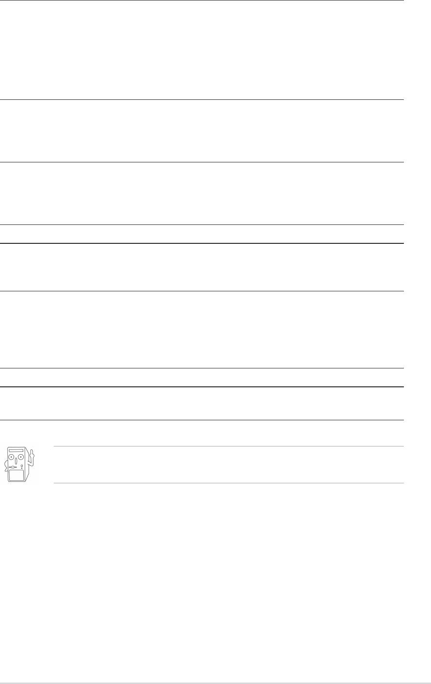
You may disable the ASUS POST Reporter™ in the BIOS setup. See
section “4.4.2 I/O Device Configuration”.
ASUS A7V8X motherboard user guide
3-3

3.3 Powering off the computer
You must first exit the operating system and shut down the system before
switching off the power. For ATX power supplies, you can press the ATX
power switch after exiting or shutting down the operating system. If you
use Windows 95/98/2000/XP, click the Start button, click Shut Down, then
click the OK button to shut down the computer. The power supply should
turn off after Windows shuts down.
The message “You can now safely turn off your computer” does not
appear when shutting down with ATX power supplies.
3-4
Chapter 3: Powering up
