Asus A7V8X: Chapter 5
Chapter 5: Asus A7V8X
Chapter 5
This chapter describes the contents of the
support CD that comes with the
motherboard package.
Software support

Chapter summary
5.1 Install an operating system........................... 5-1
5.2 Support CD information ................................ 5-1
5.3 Software information ..................................... 5-9
5.4 Using the Promise Chip for RAID 0 or 1 .... 5-26
5.5 Manual Installation of IDE/RAID drivers .... 5-34
ASUS A7V8X motherboard
5.1 Install an operating system
This motherboard supports Windows 98/ME/NT/2000/XP operating system
(OS). Always install the latest OS version and corresponding updates so
you can maximize the features of your hardware.
Because motherboard settings and hardware options vary, use the
setup procedures presented in this chapter for general reference only.
Refer to your OS documentation for more information.
5.2 Support CD information
The support CD that came with the motherboard contains useful software
and several utility drivers that enhance the motherboard features.
The contents of the support CD are subject to change at any time
without notice. Visit the ASUS website for updates.
5.2.1 Running the support CD
To begin using the support CD, simply insert the CD into your CD-ROM
drive. The CD automatically displays the welcome screen and the
installation menus if Autorun is enabled in your computer.
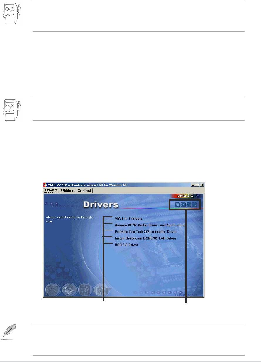
Click on a button to display
Click an icon to display
the available options
more information
If Autorun is NOT enabled in your computer, browse the contents of
the support CD to locate the file ASSETUP.EXE from the BIN folder.
Double-click the ASSETUP.EXE to run the CD.
ASUS A7V8X motherboard user guide
5-1

5.2.2 Drivers menu
The drivers menu shows the available device drivers if the system detects
installed devices. Install the necessary drivers to activate the devices.
VIA 4 in 1 drivers
This item installs the following drivers:
- VIA Registry (INF) driver
- VIA AGP VxD driver
- VIA ATAPI vendor support driver
- VIA PCI IRQ Miniport driver.
Avance AC’97 Audio Driver Applicaton
This item installs the Avance AC’97 compliant audio controller and
application.
Promise FastTrak 376 Controller Driver
This item shows the detailed information installation of the Promise
FastTrak 376 controller driver for the Serial ATA and RAID features..
BroadCom 5702 LAN Drivers or BroadCom 4401 LAN Drivers
®
On Gigabit models, this item installs the BroadCom
BCM5702 LAN
drivers for Gigabit LAN solution that provides up to 1000Mbps data
transfer rates.
®
On Fast Ethernet models, this item installs the BroadCom
BCM4401
drivers to support 10BASE-T/100BASE-TX networking.
5-2
Chapter 5: Software support
If you installed the BCM4401 controller drivers, the default setting, Wake
Up Frame, allows system wake-up from S1, S3, and S4 sleep modes. If
you wish to wake-up the system from S5 mode (shut down mode), you
must manually change the Wake-On-LAN settings to Magic Frame.
To adjust Wake-On-LAN settings:
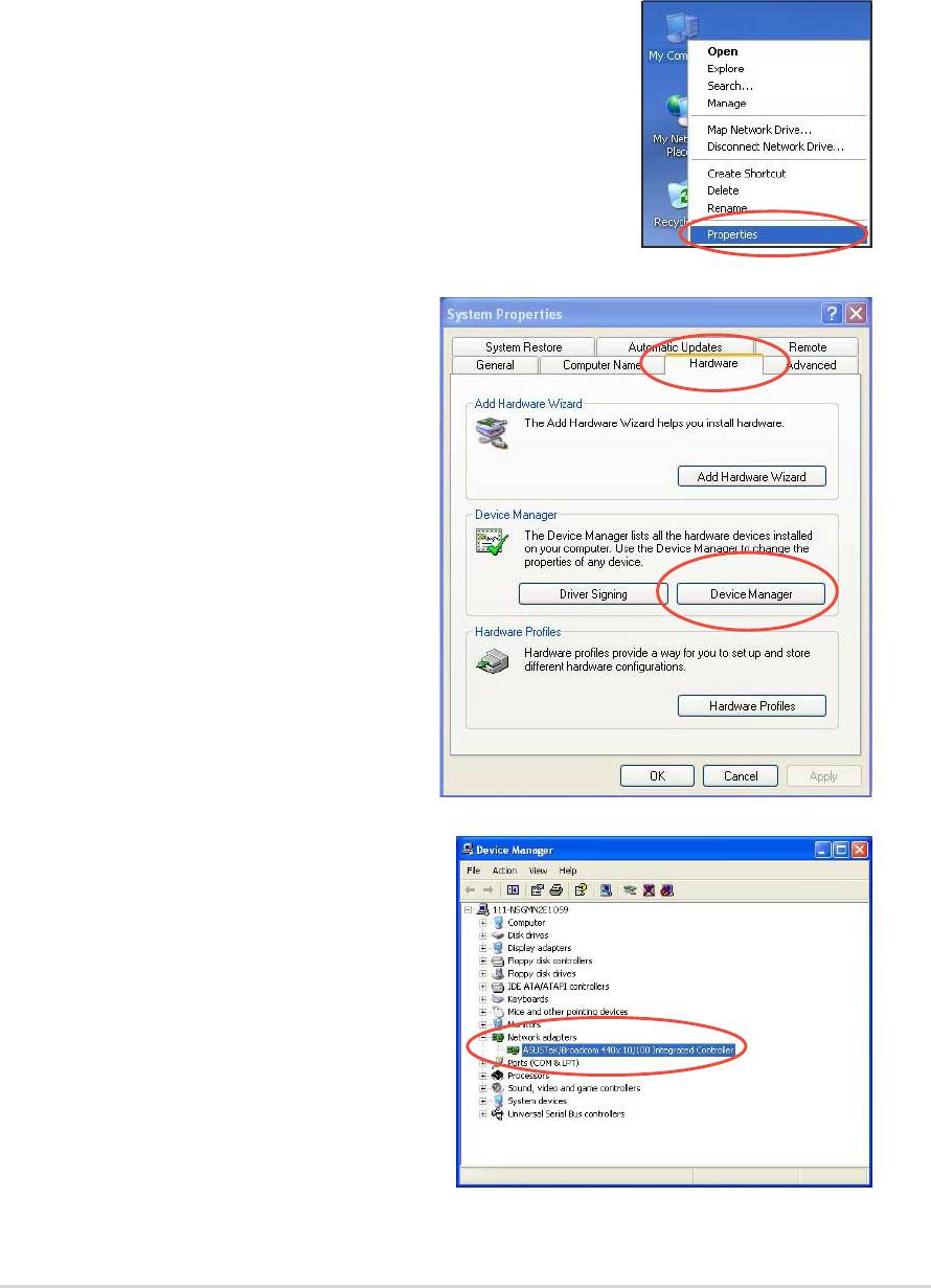
1. Right-click My Computer icon on your desktop,
and select Properties to display the System
Properties window.
2. On the System Properties
window, click on the Hardware
tab. Click on the Device
Manager button to display the
Device Manager window.
3. On the Device Manager window,
click the plus sign (+) opposite the
Network adapters item to show
the ASUSTeK/BroadCom 440x
10/100 Integrated Controller.
Double-click the item.
ASUS A7V8X motherboard user guide
5-3
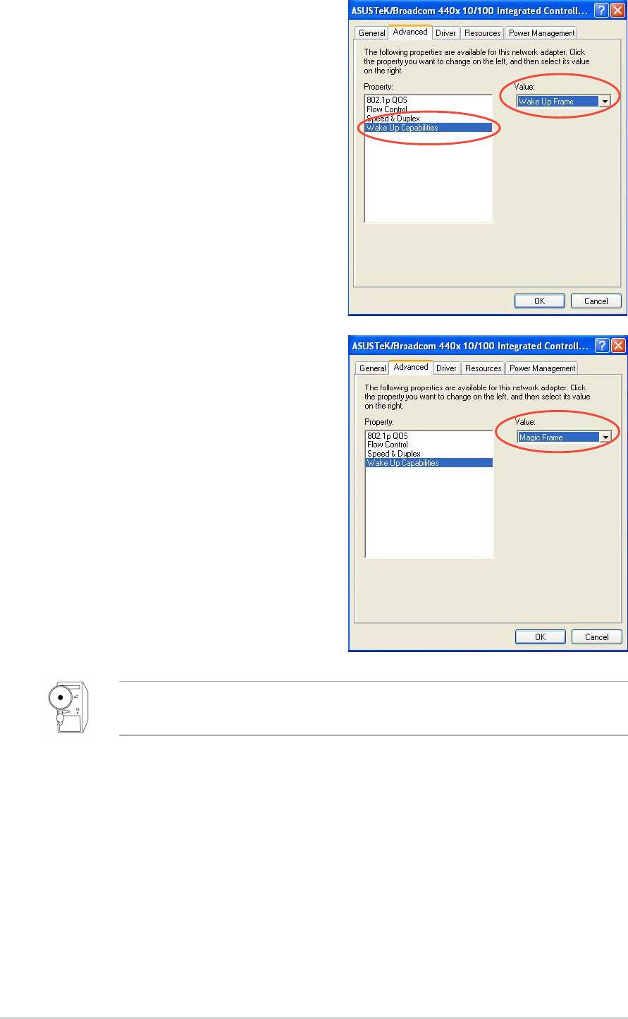
4. On the window that appears, click
the item Wake Up Capabilities
under Property. The default value
is Wake Up Frame.
The Wake Up Frame setting
wakes up the system from S1,
S3, and S4 sleep modes.
5. Click the arrow under Value to set
to Magic Frame. Click OK.
The Magic Frame setting wakes
up the system from S1, S3, S4
and S5 sleep modes.
If the BCM4401 LAN controller is onboard, the Wake-On-LAN feature
does NOT work on DOS mode.
USB 2.0 Driver
This item installs the USB 2.0 driver to upgrade your USB 1.1 ports to USB
2.0.
5-4
Chapter 5: Software support
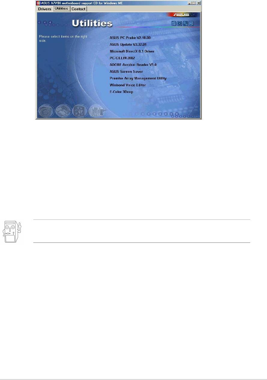
5.2.3 Utilities menu
The software menu shows the applications and other software that the
motherboard supports. Simply click on a specific item then follow the
installation wizard to install it.
ASUS PC Probe
This smart utility monitors the fan speed, CPU temperature, and system
voltages, and alerts you on any detected problems. This utility helps you
keep your computer at a healthy operating condition.
ASUS Update
This program allows you to download the latest version of the BIOS from
the ASUS website.
Before using the ASUS Update, make sure that you have an Internet
connection so you can connect to the ASUS website.
Microsoft Direct X 8.0 Driver
This item installs the Microsoft V8.0 driver.
PC-cillin 2002
This item installs the PC-cillin 2002 anti-virus software. View the PC-cillin
online help for detailed information.
Adobe Acrobat Reader
This item installs the Adobe Acrobat Reader used for reading .PDF files.
ASUS A7V8X motherboard user guide
5-5
ASUS Screen Saver
This item installs the ASUS screen saver.
Promise Array Management Utility
This item installs the RAID utility for monitoring or performing maintenance
to a FastTrak Mirrored (RAID 1) or Striped/Mirrored (RAID 0/1) disk array.
Winbond Voice Editor
This program is for recording and customizing wave files for the ASUS
POST Reporter™. Use this program if you wish to change the default
vocal POST messages. See section “3.2 Vocal POST messages” for a list
of the default messages.
E-Color 3Deep
This item installs the 3Deep software. 3Deep is the first application that
gives online gamers the competitive edge in multi-player skirmishes. This
application removes dark washed-out graphics to deliver true vibrant
colors.
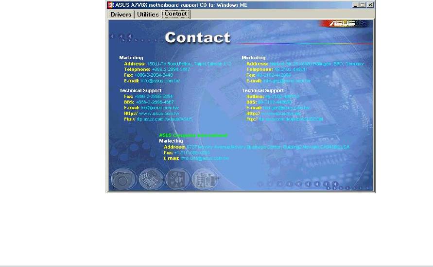
5.2.4 ASUS Contact Information
Clicking the ASUS Contact Information button displays as stated. You may
also find this information on page x of this user guide.
5-6
Chapter 5: Software support
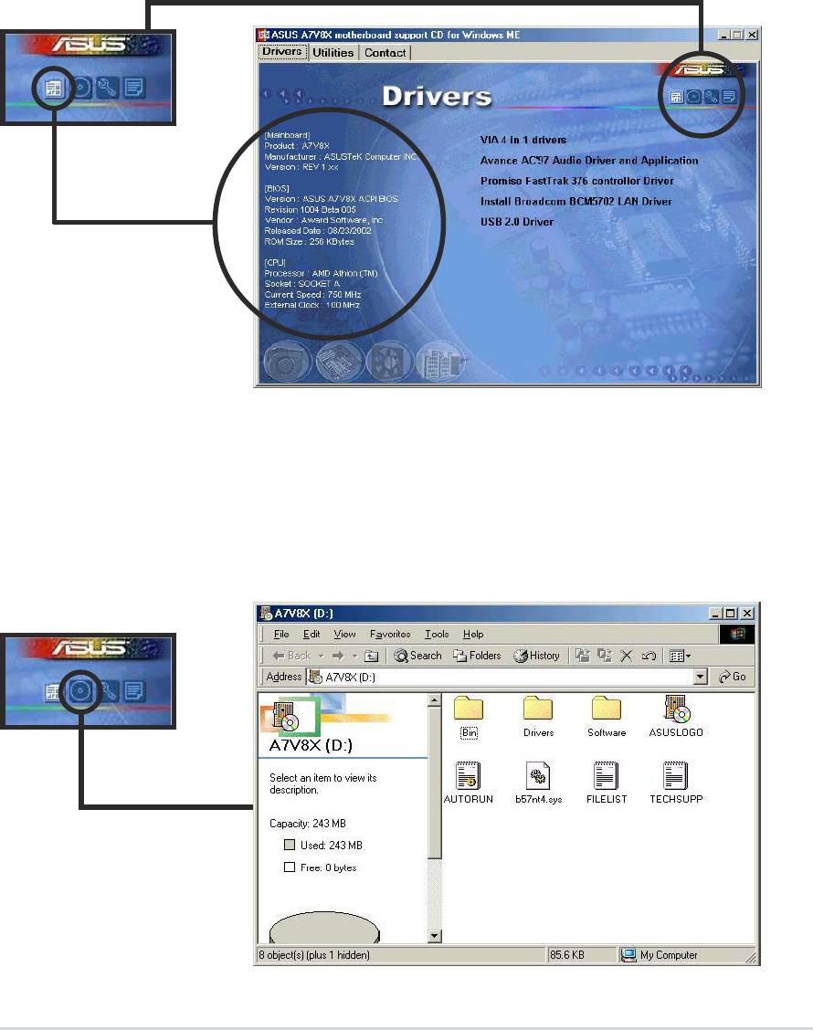
5.2.5 Other information
The icons on the left side of the screen give additional information on the
motherboard and the contents of the support CD. This section shows the
pop-up windows that appear when you click the icons.
Motherboard Info
The window displays the general specifications of the A7V8X
motherboard.
Browse this CD
The window displays the support CD contents in graphical format.
ASUS A7V8X motherboard user guide
5-7
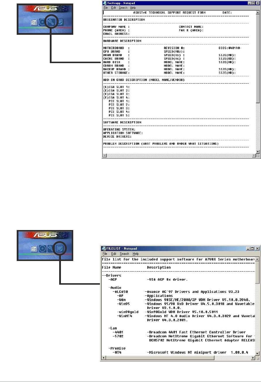
Technical Support Form
The window displays the ASUS Technical Support Request Form that you
have to fill up when requesting technical support.
Filelist
The window displays the contents of the support CD and a brief
description of each in text format.
5-8
Chapter 5: Software support
5.3 Software information
Most of the applications in the support CD have wizards that will
conveniently guide you through the installation. View the online help or
readme file that came with the software for more information.
This section provides details on the software applications that the
motherboard supports.
5.3.1 ASUS Update
The ASUS Update is a utility that allows you to update the motherboard
BIOS and drivers. This utility requires an Internet connection either
through a network or an Internet Service Provider (ISP).
Follow these steps to use the ASUS Update.
1. Launch the utility from your Windows
Start menu:
Programs/AsusUpdate Vx.xx.xx/
AsusUpdate
The ASUS Update initial screen
appears.
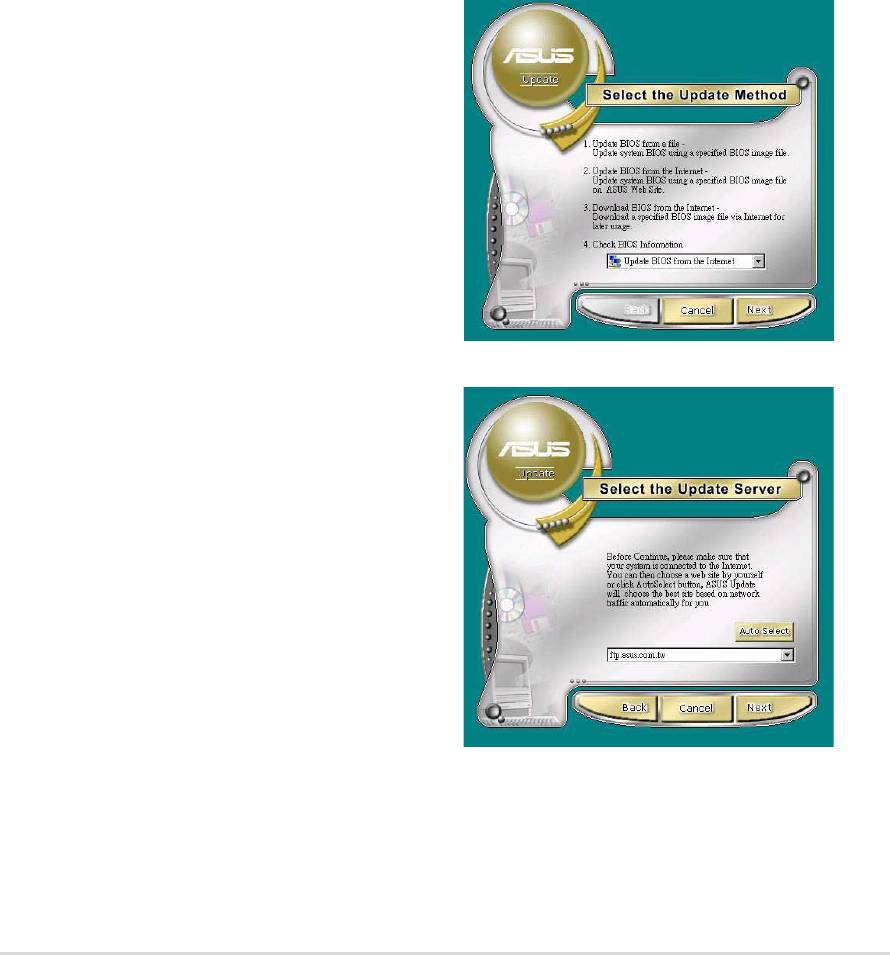
2. Select your desired update method,
then click Next.
3. If you selected updating/
downloading from the Internet,
select the ASUS FTP site nearest
you to avoid network traffic, or
choose Auto Select. Click Next.
ASUS A7V8X motherboard user guide
5-9
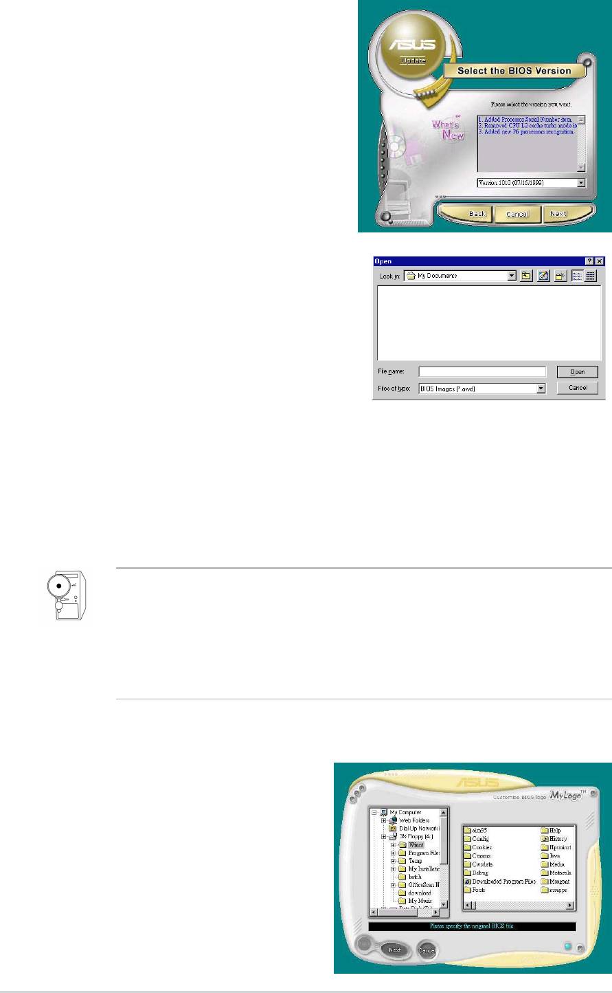
4. From the FTP site, select the
BIOS version that you wish to
download. Click Next.
5. Follow the instructions on the
succeeding screens to complete
the update process.
If you selected the option to update
the BIOS from a file, a window pops
up prompting you to locate the file.
Select the file, click Save, then follow
the screen instructions to complete
the update process.
5.3.2 ASUS MyLogo2™
The ASUS MyLogo2™ is automatically installed when you install the
ASUS Update utility from the software menu. See section “5.2.3 Software
menu”.
Before using ASUS MyLogo2 feature, use the AFLASH utility to make
a copy of your original BIOS file, or obtain the latest BIOS version from
the ASUS website.
Make sure that the BIOS item Full Screen Logo is set to [Enabled] is
you wish to use ASUS MyLogo2. See page 4-35.
Follow these steps to use ASUS MyLogo2.
1. Launch the ASUS Update utility.
See section “5.3.1 ASUS Update.”
2. When prompted for the BIOS
update method, select the option
“Update BIOS from a file.”
3. Specify the location of the BIOS
file, such as from a floppy disk.
Click Next.
5-10
Chapter 5: Software support
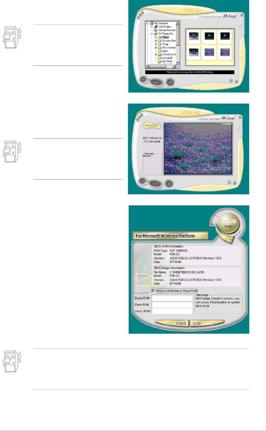
4. From the selection that appears,
choose a logo image. Click Next.
If you wish, you may create
your own boot logo image in
GIF, JPG, or BMP file
formats.
5. When you click on an image, it
displays larger on the MyLogo2
screen.
MyLogo2 may not support
too complex images. Try
using a simpler image if you
encounter any problems.
6. The next screen prompts you to
flash the original BIOS to update
it with the new boot logo. Click
Flash to update the BIOS.
7. When finished, click Exit, then
reboot your computer.
Your system boots with the new
boot logo.
Instead of starting from ASUS Update, you may also launch ASUS
MyLogo2 directly from the Windows Start menu to change your BIOS
boot logo. After you have modified the BIOS file with the new logo, use
the ASUS Update utility to upload the new BIOS into the EEPROM.
ASUS A7V8X motherboard user guide
5-11
5.3.3 ASUS PC Probe
The ASUS PC Probe is a convenient utility to continuously monitor your
computer system’s vital components, such as fan rotations, voltages, and
temperatures. It also has a utility that lets you review useful information
about your computer, such as hard disk space, memory usage, and CPU
type, CPU speed, and internal/external frequencies through the DMI
Explorer.
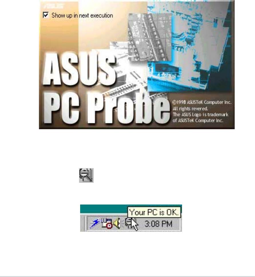
Starting ASUS PC Probe
When ASUS PC Probe starts, a splash screen appears allowing you to
select whether to show the screen again when you open PC Probe or not.
To bypass this startup screen, clear the Show up in next execution check
box.
To launch
ASUS PC Probe, click the Windows Start button, point to
Programs, and then ASUS Utility, and then click Probe Vx.xx.
The PC Probe icon appears on the taskbar system tray indicating
that ASUS PC Probe is running. Clicking the icon allows you to see the
status of your PC.
5-12
Chapter 5: Software support
Using ASUS PC Probe
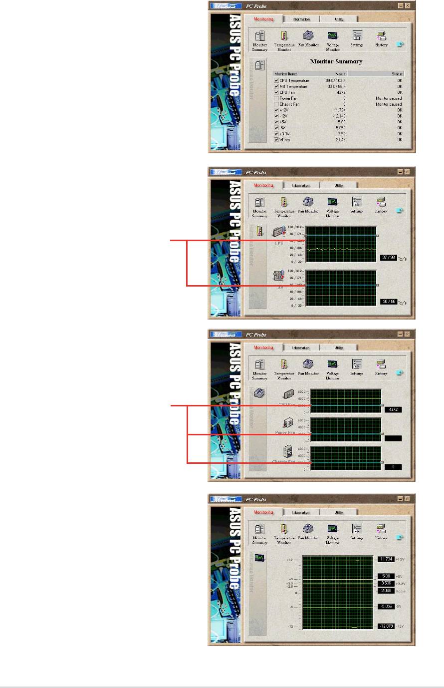
Monitoring
Monitor Summary
Shows a summary of the items
being monitored.
Temperature Monitor
Shows the PC temperature (for
supported processors only).
Temperature Warning
threshold adjustment
(Move the slider up to increase the
threshold level or down to decrease
the threshold level)
Fan Monitor
Shows the PC fan rotation.
Fan Warning
threshold adjustment
(Move the slider up to increase the
threshold level or down to decrease
the threshold level)
Voltage Monitor
Shows the PC voltages.
ASUS A7V8X motherboard user guide
5-13
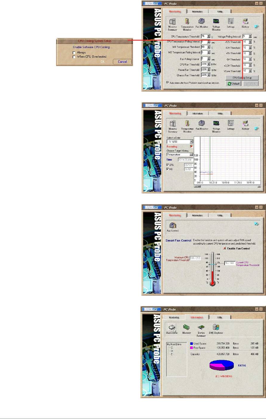
Settings
Lets you set threshold levels and
polling intervals or refresh times of
the PC’s temperature, fan rotation,
and voltages.
CPU Cooling System Setup
Lets you select when to enable software CPU
cooling. When When CPU Overheated is selected,
the CPU cooling system is enabled whenever the
CPU temperature reaches the threshold value.
History
Lets you record the monitoring
activity of a certain component of
your PC for future reference.
Fan Control
Lets you enable/disable Smart Fan
Control. Smart Fan Control adjusts
the fan speed automatically based
on the current CPU temperature
and predefined threshold.
Hard Drives
Shows the used and free space of
the PC’s hard disk drives and the
file allocation table or file system
used.
5-14
Chapter 5: Software support
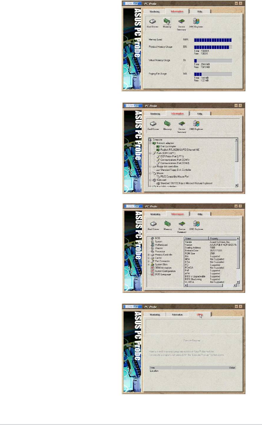
Information
Memory
Shows the PC memory load,
memory usage, and paging file
usage.
Device Summary
Shows a summary of devices
present in your PC.
DMI Explorer
Shows information pertinent to the
PC, such as CPU type, CPU
speed, and internal/external
frequencies, and memory size.
Utility
Lets you run programs outside of
the ASUS Probe modules. To run a
program, click Execute Program.
NOTE: This feature is currently
unavailable.
ASUS A7V8X motherboard user guide
5-15

ASUS PC Probe Task Bar Icon
Right clicking the PC Probe
icon brings up a menu to
open or exit ASUS PC Probe
and pause or resume all
system monitoring.
When the ASUS PC Probe
senses a problem with your PC,
portions of the ASUS PC Probe
icon change to red, the PC
speaker beeps, and the ASUS
PC Probe monitor appears.
5-16
Chapter 5: Software support
5.3.4 E-Color 3Deep
The 3Deep color tuner is designed to match your CRT or LCD color
monitor and maximize the color quality of all graphical applications. You
may also tune your internet applications to match “true” internet source
colors with the color displayed on the monitor.
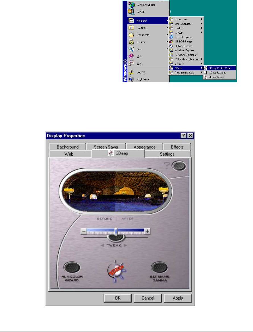
3Deep Control Panel
Using the Windows Start button,
activate the 3Deep Control Panel
program from the 3Deep Applications
group on the Main Program menu.
The control panel offers access to the Color Wizard tuning program, a
Game Gamma setting and a Tweak slider for brightness adjustment.
ASUS A7V8X motherboard user guide
5-17
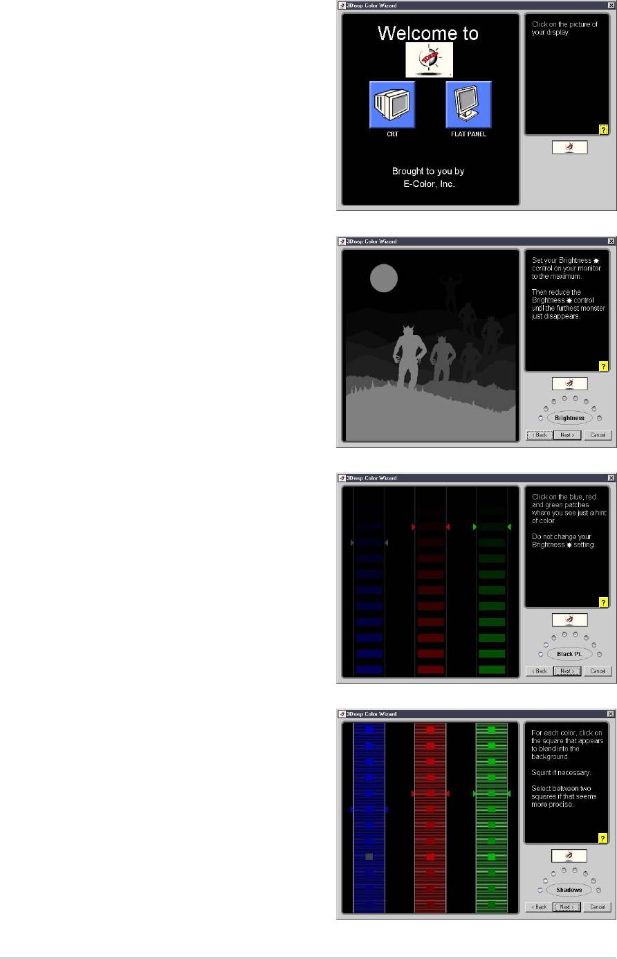
3Deep Color Tuning
1. Select the type of monitor
connected to the computer, either
CRT or LCD.
2. Follow the instructions to manually
adjust the
brightness level of the
monitor.
3. Select the faintest of the three
colors:
blue, red, and green.
4. Select the color squares that most
closely blend and match with the
background.
5-18
Chapter 5: Software support
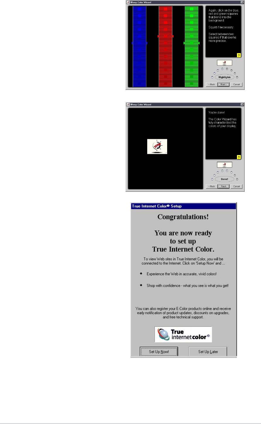
5. The next step repeats the color
matching process to achieve full
color quality.
6. When a message appears
indicating that the tuning process
is complete, click Finish.
7. Click on the Set Up Now button to
connect to the Internet. Follow the
screen instructions to set up True
Internet Color.
ASUS A7V8X motherboard user guide
5-19
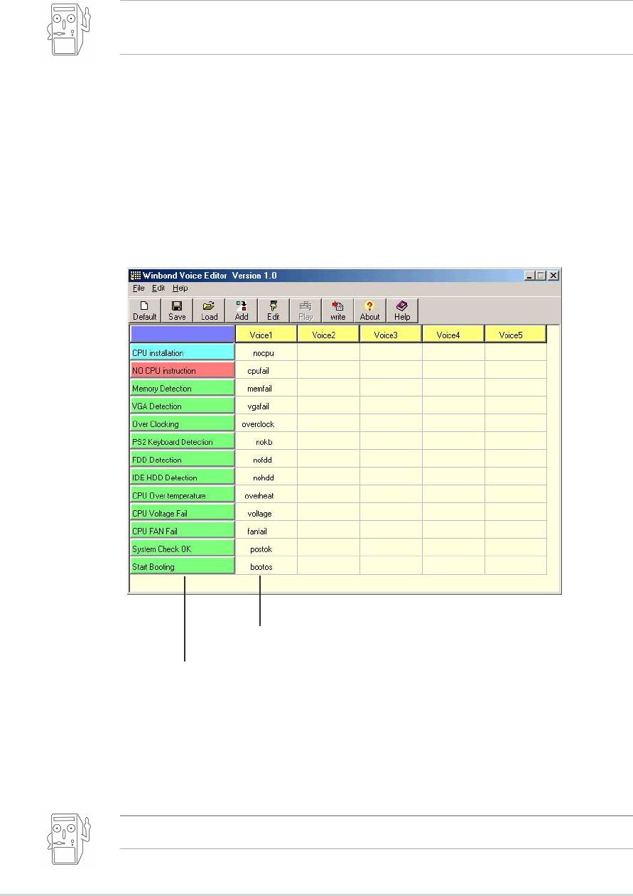
5.3.5 Winbond Voice Editor
The Winbond Voice Editor software allows you to customize the vocal
POST messages. Install the software from the software menu in the
support CD. See section “5.2.3 Software menu”.
To avoid conflicts, do not run the Winbond Voice Editor while running
the ASUS PC Probe.
Follow these steps to use the Winbond Voice Editor.
Launching the program
Launch the program either from the Winbond Voice Editor icon on your
desktop, or from the Windows Start menu, Programs/Winbond Voice Editor/
Voice Editor
.
The Winbond Voice Editor screen appears.
Default Messages
POST Events
Playing the default wave files
To play the default wave files, simply click on a POST event on the left
side of the screen, then click the Play button.
The default language setting is English.
5-20
Chapter 5: Software support
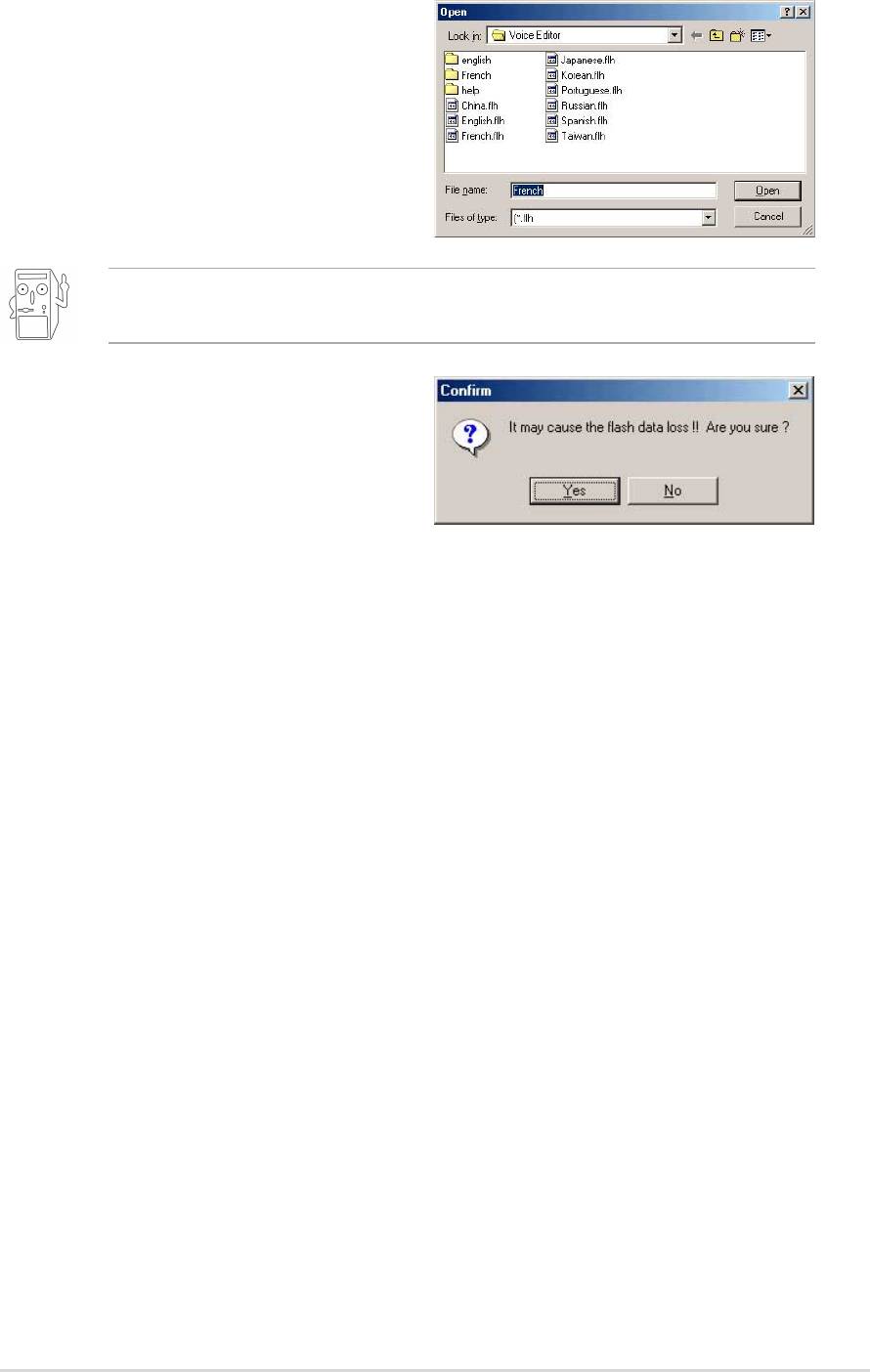
Changing the default language
1. Click on the Load button. a
window showing the available
languages appears.
2. Select your desired language then
click Open. The event messages
for the language you selected
appear on the Voice Editor screen.
For some languages, not all events have a corresponding message
due to file size constraints.
3. Click on the Write button to update
the EEPROM.
4. Click Yes on the confirmation
window that appears.
The next time you boot your computer, the POST messages are
announced in the language that you selected .
ASUS A7V8X motherboard user guide
5-21
Customizing your POST messages
If your language is not in the selection or if you wish to record your own
POST messages to replace the pre-installed wave files, you may easily do
so.
Follow these steps to customize your POST messages.
1. Launch the Voice Editor and take note of the list of POST events on
the leftmost column of the screen.
2. Prepare your message for each event.
The total compressed size for all the wave files must not exceed 1Mbit,
so make your messages as short as possible.
3. Use a recording software, such as Windows Recorder, to record your
messages.
4. Save the messages as wave files (.WAV). It is recommended that you
save your files in low quality to keep them small. For example, use
8-bit, mono quality at 22Khz sampling rate.
You may want to create a separate folder for your wave files so you
can locate them easily in one place.
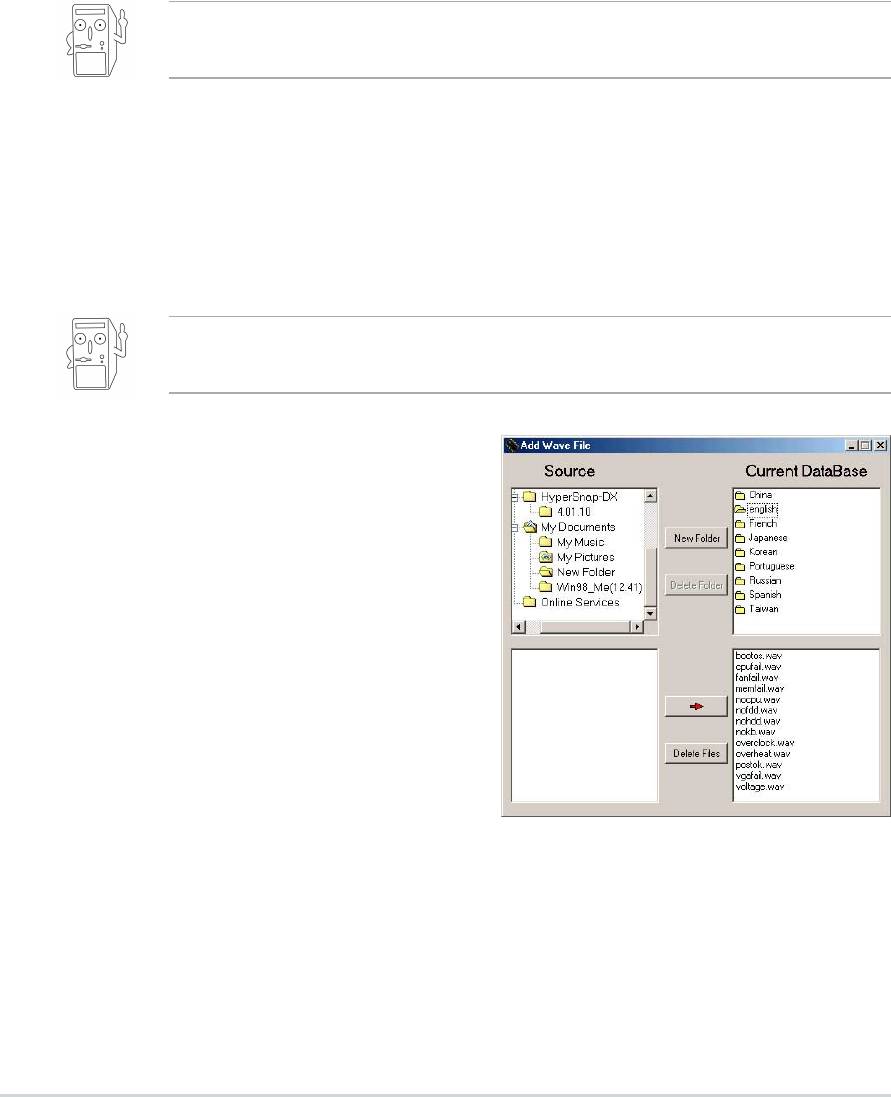
5. From the Voice Editor screen,
click on the Add button to display
the Add Wave File window.
6. Copy the wave files that you
recorded to the database. Close
the window when done.
5-22
Chapter 5: Software support
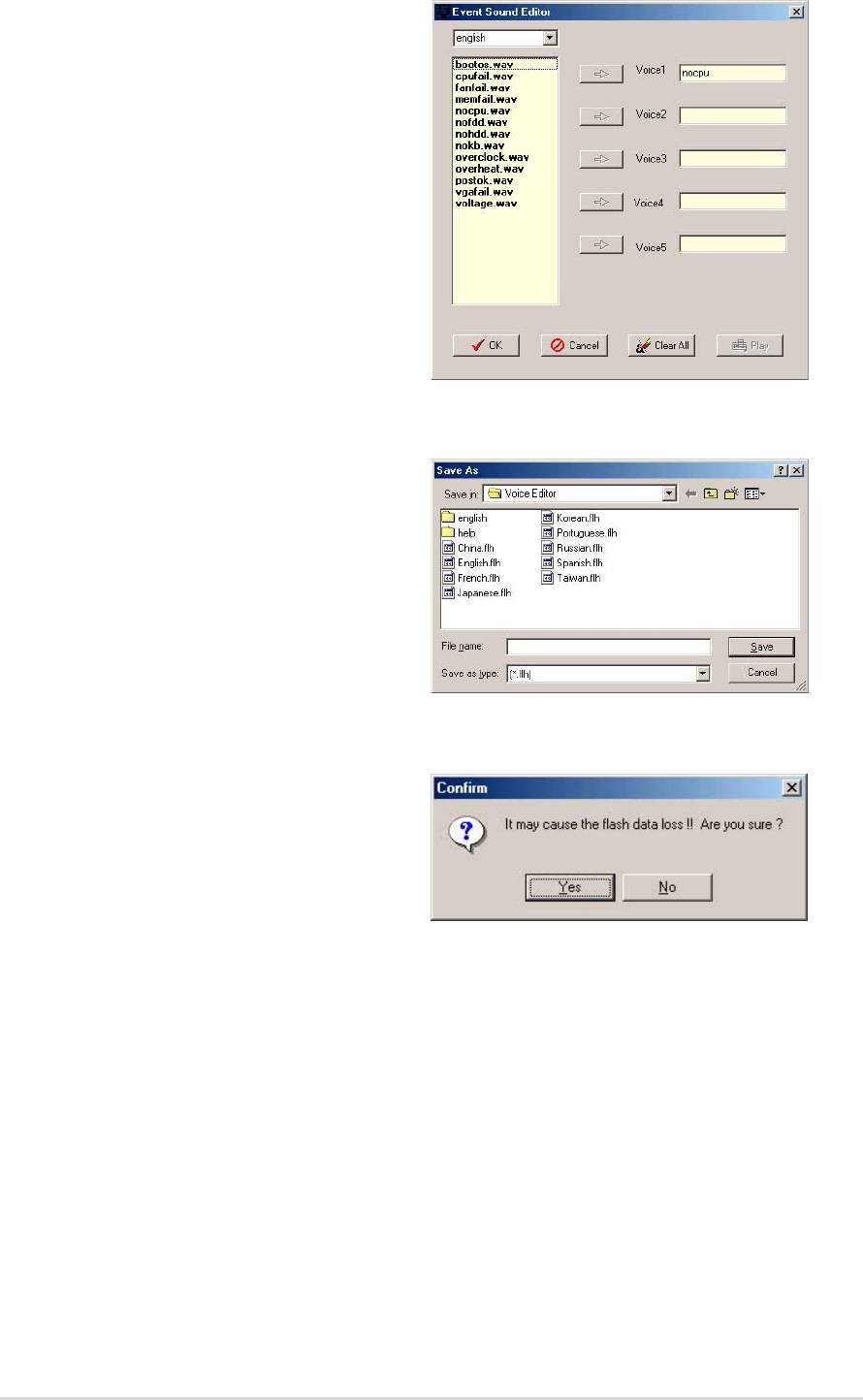
7. Click a POST event on the Voice
Editor screen, then on the Edit
button. The Event Sound Editor
window appears.
8. Locate and select your wave file
for the event then click on the
arrow opposite Voice1. The file
you selected appears on the
space next to it.
9. Click OK to return to the Voice
Editor screen.
10.Do steps 7 to 9 for the other
events.
11. When done, click the Save
button. A window appears
prompting you to save your
configuration.
12.Type a file name with a
.flh
extension, then click Save.
13.Click on the Write button to
compress the file and copy into
the EEPROM.
14.Click Yes on the confirmation
window that appears.
If you receive an error message telling you that the files exceed the total
allowable size, do one or all of the following.
• Try to modify your messages to make them shorter
• Save the wave files at a lower quality
• Skip lesser used events like FDD Detection, IDE HDD Detection, etc.
ASUS A7V8X motherboard user guide
5-23
5.3.6 Multi-Channel Audio Feature
The RealTek ALC650 6-channel AC’97 Audio Driver and Applications are
included in the support CD that came with your motherboard package.
Install these programs to enable the multi-channel audio feature.
You must use 4 or 6 channel speakers for this setup.
Setting the RealTek ALC650 AC’97 Audio Configuration
1. Install the RealTek ALC650 AC’97 audio driver from the support CD.
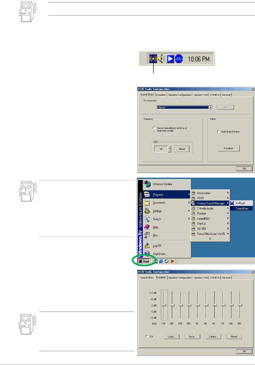
2. After installation, the RealTek
“Sound Effect” icon appears on the
bottom right of the screen.
Sound Effect Icon
3. Click on the Sound Effect icon to
display the RealTek ALC650 AC97
Audio Configuration dialogue box.
Transform the sound environment,
set to Karaoke or load the
Equalizer from the Sound Effect
tab.
You may also launch the ALC650
AC97 Audio Application by
clicking on the Start button on
your Windows desktop, then
select Programs > Audio Sound
Manager > SoundMan
4. Click on the Equalizer tab to
display panel to individually control
frequency bands and adjust sound
output.
You may also display the
Equalizer panel by clicking on the
Equalizer command button on the
Sound Effect tab.
5-24
Chapter 5: Software support
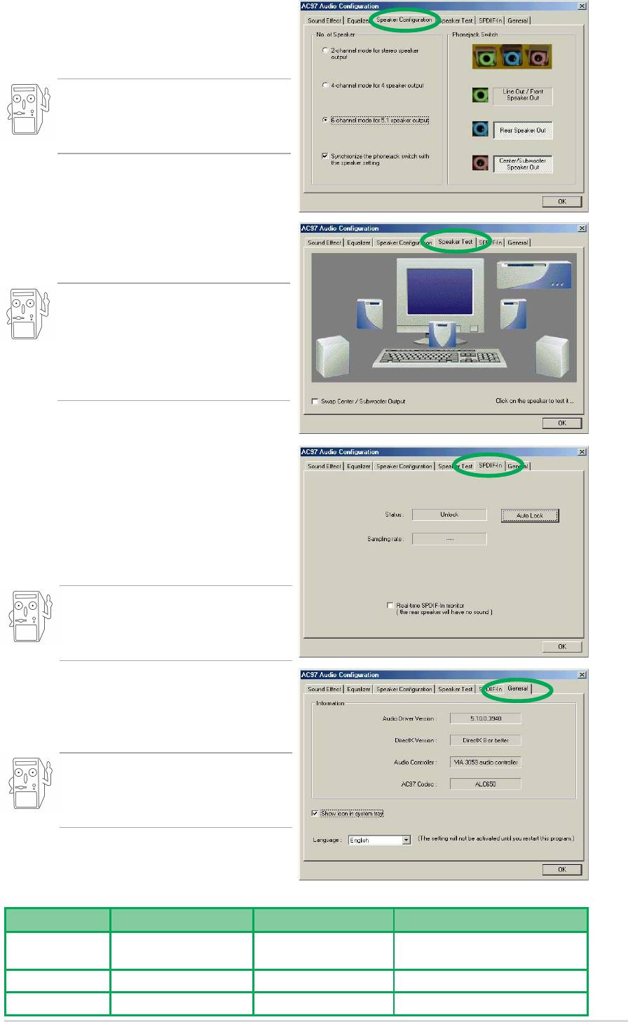
5. Click on the
Speaker Configuration tab to
customize your speaker system.
Make sure to select the correct
speaker channel mode based on
your actual speaker setup.
6. Click on the Speaker Test tab for
the Multi-channel audio test.
When you use the 6-channel
function and your speaker
Center/Subwoofer channel is
incorrect, select Swap Center/
Subwoofer Output.
7. Click on the SPDIF-In tab for the
configuration.The ALC650 by
default enable the SPDIF Out
function.If you use the SPDIF-In
function, the SPDIF frequency will
be locked by the ALC650 chip.
The AC-3 SPDIF-In function is not
supported by ALC650, it only
supports stereo SPDIF-In.
8. Click on the General tab for
version information and multi-
language settings.
English is the default setting when
you first install the audio
programs package.
Connector Settings and Functions
Connector Headphone/2 Speaker 4-Speaker 6-Speaker
Lime Line Out/ Line Out/ Line Out/
Front Speaker Out Front Speaker Out Front Speaker Out
Light Blue Line In Rear Speaker Out Rear Speaker Out
Pink Mic In Mic In Center Speaker Out, Sub-woofer
ASUS A7V8X motherboard user guide
5-25

5.4 RAID 0/RAID 1 configurations
®
The motherboard includes the Promise
PDC20376 controller chipset, two
Serial ATA interfaces, and a Parallel ATA133 interface to support
Redundant Array of Independent Disks (RAID) configuration. This feature
supports Ultra ATA/133 drives, and is backward compatible with Ultra ATA/
100/66/33 drives. Use the MBFastTrak376™ BIOS and the FastBuild™
utility to configure a disk array.
RAID 0 (called data striping) optimizes two identical hard disk drives to
read and write data in parallel, interleaved stacks. Two hard disks perform
the same work as a single drive but at a sustained data transfer rate,
double that of a single disk alone, thus improving data access and
storage.
RAID 1 (called data mirroring) copies and maintains an identical image of
data from one drive to a second drive. If one drive fails, the disk array
management software directs all applications to the surviving drive as it
contains a complete copy of the data in the other drive. This RAID
configuration provides data protection and increases fault tolerance to the
entire system.
5.4.1 Install the hard disks
The PDC20376 chipset supports Ultra ATA/133/100/66 hard disk drives.
For optimal performance, install identical drives of the same model and
capacity when creating a disk array.
• If you are creating a RAID 0 (striping) array for perfomance, use two
new drives.
• If you are creating a RAID 1 (mirroring) array for protection, you can use
two new drives or use an existing drive and a new drive (the new drive
must be of the same size or larger than the existing drive).
The chipset supports RAID 0 (striping) or RAID 1 (mirroring) for master
drives only.
The Promise PDC20376 chipset only supports one Master HDD on
the PRI_RAID1 connector. HDDs set to Slave mode and ATAPI
devices such as CD-ROMs, DVD-ROMs, etc. are not supported.
5-26
Chapter 5: Software support

Follow these steps to install the hard disks for RAID configuration.
1. Set the jumpers of each hard disk as Master.
2. Install the hard disks into the drive bays.
3. Connect the HDD cables. Three connection options are available for
creating a RAID 0 or RAID 1 array:
a) Connect one Parallel ATA HDD to PRI_RAID1 connector and one
Serial ATA HDD to either one of the two Serial ATA connectors,
using separate parallel ATA or serial ATA cables.
b) Connect one Serial ATA HDD to each Serial ATA connector, using
separate serial ATA cables.
c) Connect one Serial ATA HDD to the PRI_RAID1 connector, and
one Serial ATA HDD to either one of the two serial ATA
connectors, using separate parallel/serial ATA cables.
4. Connect the power cable to the power connector on each drive.
5. Boot the system and enter the BIOS Setup Utility.
6. Go to the
Advanced menu and select PCI Configuration. Make sure that
the Onboard SATA/IDE RAID Controller field is set to Enabled, and the
Onboard ATA Device First field set to Yes.
7. Save your changes and Exit Setup.
8. Proceed to section 5.4.2 for the next procedure.
ASUS A7V8X motherboard user guide
5-27
5.4.2 Enter the MBFastBuild™ utility
1. Boot the system.
If this is the first time you boot the system with the new hard disks
installed and connected to the ATAIDE connectors on the
motherboard, the MBFastTrak376™ BIOS displays the following:
2. Press <Ctrl-F> simultaneously to display the FastBuild™ utility main
menu.
MBFastBuild (tm) Utility 1.21 (c) 1996-2001 Promise Technology, Inc.
Auto Setup . . . . . . . . . . [ 1 ]
5-28
Chapter 5: Software support
[ 1 ]
View Drive Assignments . . . . [ 2 ]
[ 2 ]
View Array . . . . . . . . . . [ 3 ]
[ 3 ]
Delete Array . . . . . . . . . [ 4 ]
[ 4 ]
Rebuild Array. . . . . . . . . [ 5 ]
[ 5 ]
Controller Configuration . . . [ 6 ]
[ 6 ]
MBFastTrak376 (tm) BIOS version 1.00
(c)2000-2005 Promise Technology, Inc. All Rights Reserved.
No Array defined...
Press <Ctrl-F> to enter FastBuild (tm) Utility
Or press <ESC> key to continue booting.
[ Main Menu ]
[ Keys Available ]
Press 1..6 to select Option [ESC] Exit
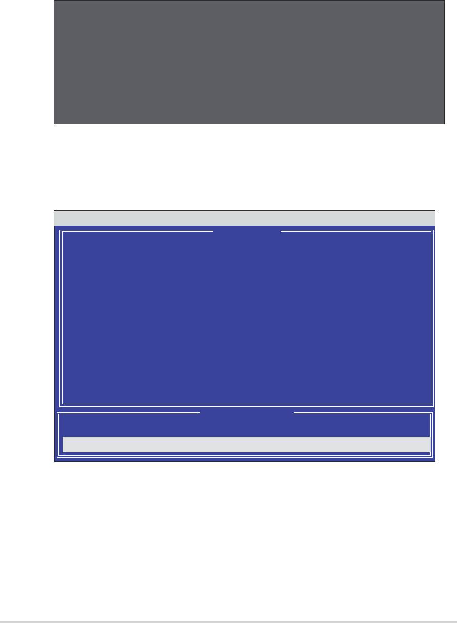
5.4.3 Creating a RAID 0 array (Performance)
1. In the FastBuild™ utility main menu, press “1” to select Auto Setup.
The following screen appears.
2. Use the arrow keys to go to the field
Optimize Array for and select
“Performance” with the space bar. The Mode field displays “Stripe”.
3. After making a selection, press <Ctrl-Y> to save and create a RAID 0
array.
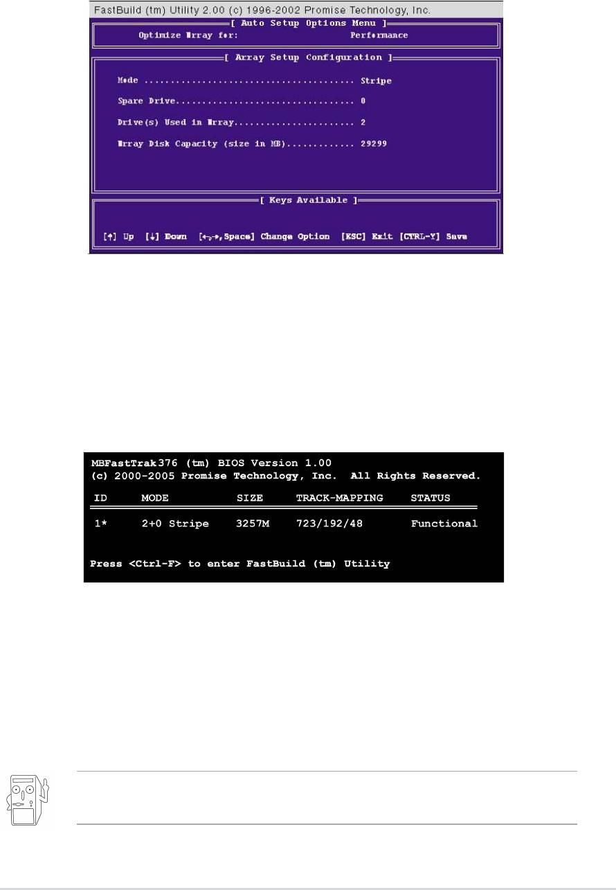
4. Press any key to reboot the system. During the boot process, the
MBFastTrak376 BIOS checks and displays the disk array information.
5. Once the array is created, use the FDISK utility to format the array as a
single hard drive.
6. After you have formatted the arrayed drives, install an operating
system (OS). The OS will treat the RAID 0 array as a single drive unit.
7. Install the RAID driver from the support CD that came with the
motherboard package.
Depending on the operating system you are installing, you may need
to install the RAID driver during or after the OS installation.
ASUS A7V8X motherboard user guide
5-29
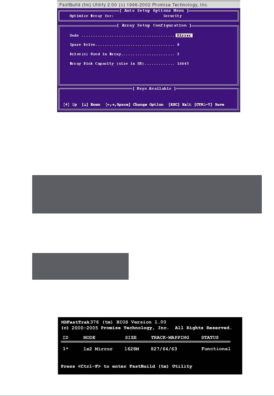
5.4.4 Creating a RAID 1 array (Security)
Creating a Security Array with New Drives
1. In the FastBuild™ utility main menu, press “1” to select Auto Setup.
2. Use the arrow keys to go to the field Optimize Array for and select
“Security” with the space bar. The Mode field displays “Mirror”.
3. Press <Ctrl-Y> to save your selection.
4. The following message appears:
Do you want the disk image to be duplicated to another? (Yes/No)
Y - Create and Duplicate
N - Create Only
5. Press N for the Create Only option. A message appears confirming that
your Security array has been created.
Array has been created.
<Press any key to reboot>
6. Press any key to reboot the system. During the boot process, the
MBFastTrak376 BIOS checks and displays the disk array information.
5-30
Chapter 5: Software support

7. Use the FDISK utility and follow the format procedure for installing a
new hard drive. After you have formatted the arrayed drives, install an
operating system (OS).
8. Install the RAID driver from the support CD that came with the
motherboard package.
Depending on the operating system you are installing, you may need
to install the RAID driver during or after the OS installation.
Creating a Security Array with Existing Data Drive
If you would like to use an existing drive that already contains data and/or
is the bootable drive in your system, make sure that the new hard drive
you will use in the array has the same or larger capacity as the existing
drive.
Backup all important data before creating an array. Failure to do so
may cause data loss.
1. In the FastBuild™ utility main menu, press “1” to select Auto Setup.
2. Use the arrow keys to go to the field
Optimize Array for and select
“Security” with the space bar. The Mode field displays “Mirror”.
3. Press <Ctrl-Y> to save your selection. The following message
appears:
Do you want the disk image to be duplicated to another? (Yes/No)
Y - Create and Duplicate
N - Create Only
5. Press Y for the Create and Duplicate option. The next window prompts
you to select the source drive to use.
6. Use the arrow keys to select the source drive. The FastBuild utility will
copy all the data from the source drive to the target drive.
7. Press <Ctrl-Y> to save the selection and start the duplication. The
following message appears:
Start to duplicate the image...
Do you want to continue? (Yes/No)
Y - Continue N - Abort
ASUS A7V8X motherboard user guide
5-31

8. Select Y to continue. Select N to return to the main menu.
9. When the duplication process is completed, a message appears
confirming that your Security array has been created.
10.Press any key to reboot the system.
11. Install the RAID driver from the support CD that came with the
motherboard package.
Depending on the operating system you are installing (or that is
already installed), the RAID driver installation sequence may vary.
5.4.5 Other FastBuild Utility Commands
Command options 3-6 on the FastBuild™ Utility main menu are not
required for setting up an array, but they are useful for reconfiguring an
array.
View Array (3): This command allows you to view the drive assignments
of hard disks in an array.
Delete Array (4): This command deletes an array to reconfigure the
system. Deleting an array does not remove information on the hard disks.
If an array is deleted by mistake, recover it immediately by redefining it as
the deleted array.
Rebuild Array (5): This command restores the array and system data
after faults on RAID 1 arrays.
Follow these steps to rebuild and restore data in the array:
1. On boot-up, an error message notifies of a system failure.
2. Press <Ctrl-F> to enter the FastBuild™Main Menu.
3. Select <3> for View Array to verify the ID of the defunct hard disk.
4. Power off the system and replace the hard disk with an identical model.
5. Reboot and enter the FastBuild™ Main Menu again.
6. Select <5> for Rebuild Array. The malfunctioning array is highlighted.
Press Enter to select.
5-32
Chapter 5: Software support
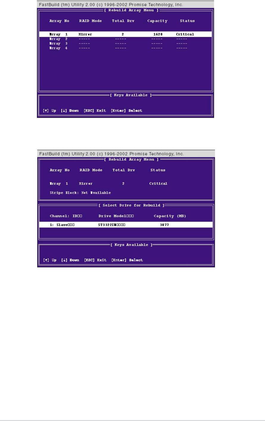
7. Select the replacement drive. Press <Enter>.
8. Confirm the command to copy data from the intact source hard disk
onto a new replacement hard disk. A progress gauge displays the
copy progress for the duration of the task.
9. After the rebuild processis complete, the user is prompted to reboot the
system.
Controller Configuration (6): This command shows the default for
Controller Configuration. The default value is [Enabled].
ASUS A7V8X motherboard user guide
5-33

5.5 Manual Installation of IDE/RAID Drivers
The A7V8X support CD contains several IDE and RAID 0 or 1 drivers in the
Promise folder, including Windows, NetWare and NT4. Below follow two
popular OS installations. The others are available on the support CD.
®
™
5.5.1 Win9x-ME Promise
FastTrak376
Driver
1. Ensure the Support CD-ROM is in the CD Drive and press “Start”
button.
2. Move highlight bar to “Settings” and select “Control Panel”.
3. Double click on “System” icon.
4. Select “Device Manager” page.
5. View device by type and find “Other devices” node.
4. Select the “PCI Mass Storage Controller” node and then click
“Properties.”
6. Please select [General] page to reinstall driver or select [Driver] page
to update the driver.
7. Follow the instruction to insert your Windows CD or ASUS support CD
to install the driver.
(Driver Location: {CD-ROM driver}:\Promise\Raid0or1\Win9x-ME)
®
™
5.5.2 Win2000 / XP Promise
FastTrak376
Driver
1. Right click “My Computer” icon on the desktop. Select “Properties”
when the menu appears. Or you can Press “Start” button. Move
highlight bar to “Settings” and select: “Control Panel”. Double click
on “System” icon.
2. Select “Hardware” page and then click [Device Manager] button.
3. View device by type and find “Other devices” node.
4. Right Click the “Mass Storage Controller” node.
5. When the menu appears, click the “Properties” item.
6. Please select select [Driver] page to update driver.
7. Press Next while “Upgrade Device Driver Wizard” window appears.
8. Choose “Select for a suitable driver for my device(recommended)”
option and then press Next.
9. Select “Specify a location” check box.
10. Type or browse the path {CD-ROM Drive}: \Promise \Raid0or1
\Win2000 to the driver and click OK.
11. Press Next.
12. Press Yes.
13. Finally, press Finish to complete the installation.
14. Please restart you computer for these changes to take effect.
(Driver Location: {CD-ROM driver}:\Promise\Raid0or1\Win2000)
5-34
Chapter 5: Software support

®
™
5.5.3 Win NT Promise
FastTrak376
Driver
1. Press “Start” button.
2. Move highlight bar to “Settings” and select “Control Panel”.
3. Double click on “SCSI Adapters” icon.
4. Select “Driver” page.
5. Press “Add...” button.
6. Select item “Unlisted or Updated Driver” in “List of Drivers” list box.
7. Specify path {CD-ROM Drive}:\Drivers\Promise\NT4 to the driver.
8. When dialog appears, select “WinNT Promise FastTrak376 (tm) Lite
Controller” item from the list and press “OK” button.
9. Please restart Windows NT system.
®
™
5.5.4 Installing the Promise
FastTrak376
Driver in
a New Windows 2000 / XP System
1. Read ASUS support CD in another PC and click Browse Support CD.
2. Click Driver folder.
3. Click Promise folder.
4. Select the Promise chip used on your motherboard and click on it.
5. For example, we want to use RAID 0 function on A7V8X motherboard
under Windows XP. The Promise RAID chip on A7V8X is PDC20276.
Accordingly, look for the files in the appropriate Promise Chip folder:
WinXP, FASTTRAK, README, and TXTSETUP.OEM. Copy these three
files to a floppy diskette.
6. Go back to your new RAID motherboard.
7. If available, make sure the RAID_SW jumper on the motherboard is
enabled and enable the appropriate fields in the BIOS.
8. Insert a Windows 2000 or XP installation CD.
9. Boot from CD-ROM.
10.Start to install Windows 2000 or XP.
11. The operation system installation program will ask you “Press F6 if you
want to install a third party SCSI or RAID driver.”
12. Quickly press F6 when you see “Press F6 if you want to install a third
party SCSI or RAID driver.”
13. Press S to set up RAID controller.
14. Insert the floppy diskette with the files you copied earlier.
™
15. Choose WinXP Promise FastTrak376
Controller.
16. The RAID system is now setup to work with the XP or 2000 platform.
Complete the Windows OS installation process.
ASUS A7V8X motherboard user guide
5-35

5-36
Chapter 5: Software support
