Asus A7V8X: Chapter 2
Chapter 2: Asus A7V8X
Chapter 2
This chapter describes the hardware setup
procedures that you have to perform when
installing system components. It includes
details on the switches, jumpers, and
connectors on the motherboard.
Hardware information

Chapter summary
2.1 Motherboard installation ............................... 2-1
2.2 Motherboard layout ....................................... 2-2
2.3 Before you proceed ....................................... 2-3
2.4 Central Processing Unit (CPU) ..................... 2-4
2.5 System memory ............................................. 2-6
2.6 Expansion slots ............................................2-11
2.7 Switches and jumpers ................................. 2-14
2.8 Connectors ................................................... 2-18
ASUS A7V8X motherboard
2.1 Motherboard installation
Before you install the motherboard, study the configuration of your chassis
to ensure that the motherboard fits into it. The A7V8X uses the ATX form
factor that measures 12 inches x 9.6 inches (30.5 x 24.5 cm).
Make sure to unplug the power cord before installing or removing the
motherboard. Failure to do so may cause you physical injury and
damage motherboard components.
2.1.1 Placement direction
When installing the motherboard, make sure that you place it into the
chassis in the correct orientation. The edge with external ports goes to the
rear part of the chassis as indicated in the image below.
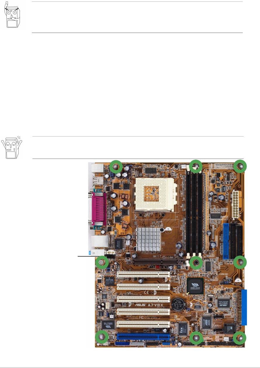
2.1.2 Screw holes
Place nine (9) screws into the holes indicated by circles to secure the
motherboard to the chassis.
Do not overtighten the screws! Doing so may damage the
motherboard.
Place this side towards
the rear of the chassis
ASUS A7V8X motherboard user guide
2-1
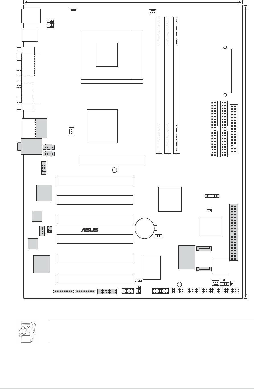
2.2 Motherboard layout
24.5cm (9.6in)
OVER_VOLT1
PS/2KBMS
CPU_FAN1
T: Mouse
B: Keyboard
KBPWR1
USBPWR_12
USBPWR_34
USB1.1
T: USB0
B: USB1
COM1
Socket 462
PARALLEL PORT
ATX Power Connector
COM2
VIA
USB2.0
DDR DIMM1 (64/72 bit, 184-pin module)
DDR DIMM2 (64/72 bit, 184-pin module)
DDR DIMM3 (64/72 bit, 184-pin module)
Top:
T: USB1
KT400
RJ-45
B: USB2
Chipset
PWR_FAN1
Top:Line In
Center:Line Out
AUX1
Below:Mic In
0 1
2 3
4 5
FLOPPY1
CD1
Accelerated Graphics Port (AGP Pro)
AGP_WARN1
PRI_ IDE1
30.5cm (12.0in)
FP_AUDIO1
SEC_ IDE1
PCI1
GBLAN
or
LAN
VIA
SMB_CON1
Chip
PCI2
VT8235
Chipset
TRPWR1
Audio
Codec
PCI3
ASUS
CR2032 3V
ASIC
®
Lithium Cell
SPDIF1
A7V8X
with Hardware
CMOS Power
Monitor
MODEM1
CLRTC1
PCI4
SPEECH
Controller
SEC_SATA1
VIA
PCI5
4Mbit
1394
SerialATA
Controller
PRI_RAID1
PDC20376
PROMISE
Firmware
Controller
Hub
I/O
PRI_SATA1
USBPWR_56
Super
CHASSIS1
PCI6
SB_PWR1
USB56
SMARTCARD1
CHA_FAN1
IDELED1
IEEE1394_1
IEEE1394_2
GAME1
WPCI_USB1
IR_CON1
AFPANEL1
PANEL1
The audio, SATA, Gigabit LAN, LAN and 1394 features are optional.
These components are grayed out in the above motherboard layout.
2-2
Chapter 2: Hardware information
2.3 Before you proceed
Take note of the following precautions before you install motherboard
components or change any motherboard settings.
1. Unplug the power cord from the wall socket before touching any
component.
2. Use a grounded wrist strap or touch a safely grounded object or to
a metal object, such as the power supply case, before handling
components to avoid damaging them due to static electricity.
3. Hold components by the edges to avoid touching the ICs on them.
4. Whenever you uninstall any component, place it on a grounded
antistatic pad or in the bag that came with the component.
5. Before you install or remove any component, ensure that the
ATX power supply is switched off or the power cord is
detached from the power supply. Failure to do so may cause
severe damage to the motherboard, peripherals, and/or
components.
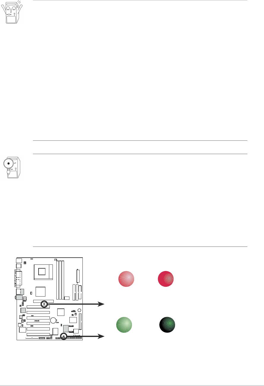
When lit, the green LED (SB_PWR1) indicates that the system is ON,
in sleep mode, or in soft-off mode, a reminder that you should shut
down the system before removing or plugging in any motherboard
component.
The red LED (AGP_WARN1) is a smart protection from motherboard
burn out caused by an incorrect AGP card. If you plug in any 3.3V AGP
card into the 1.5V AGP slot, this LED lights up thus preventing the
system to power up. This LED remains off if you plug in a 1.5V AGP
card.
AGP_WARN1
ON
OFF
Incorrect
Correct
AGP Card
AGP Card
SB_PWR1
®
A7V8X
ON
OFF
Standby
Powered
A7V8X Onboard LED
Power
Off
ASUS A7V8X motherboard user guide
2-3
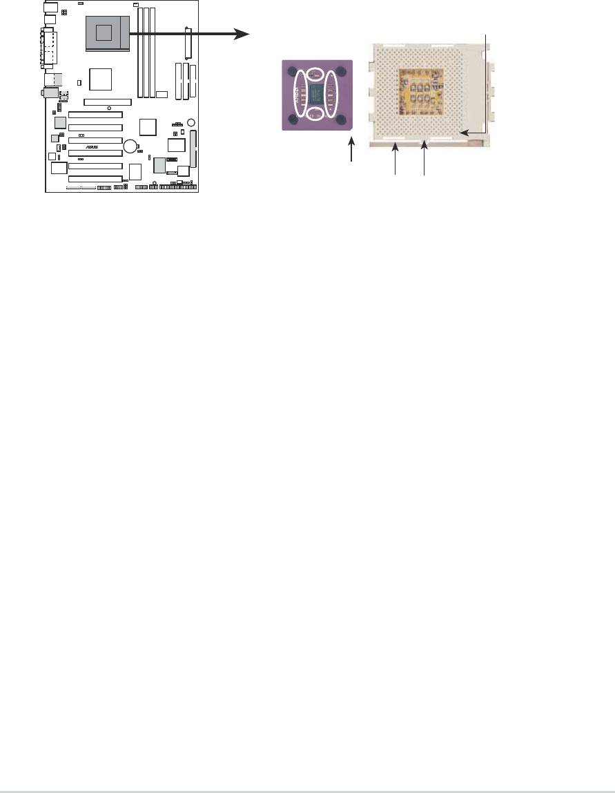
2.4 Central Processing Unit (CPU)
2.4.1 Overview
The motherboard provides a Socket A (462) for CPU installation. AMD
processors offer gigahertz speeds to support all the latest computing platforms
TM
TM
TM
and applications. The A7V8X supports Athlon
XP/Athlon
and Duron
processors.
CPU NOTCH
TO INNER
CORNER
AMD™ CPU
A7V8X
®
CPU NOTCH
LEVER
LOCK
A7V8X Socket A
Each AMD CPU has a “marked” corner. This corner is indicated with a notch,
and/or a golden square or triangle. Refer to this indicator while orienting the
CPU. See the next section for installation details.
A fan and heatsink should be attached to the CPU to prevent overheating.
2-4
Chapter 2: Hardware information
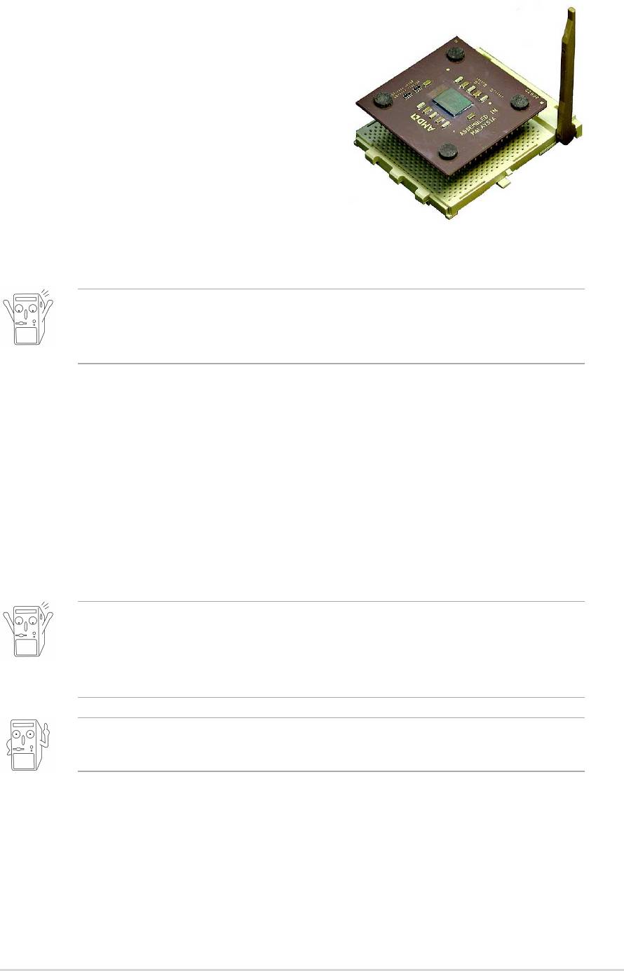
2.4.2 Installing the CPU
Follow these steps to install a CPU:
1. Locate the Socket 462 and open it by
pulling the lever gently sideways away
from the socket. Then lift the lever
upwards. The socket lever must be fully
opened (90 to 100 degrees).
2. Insert the CPU with the correct
orientation. The notched or golden
corner of the CPU must be oriented
toward the inner corner of the socket
base nearest to the lever hinge.
The CPU should drop easily into place. Do not force the CPU into the
socket to avoid bending the pins. If the CPU does not fit, check its
alignment and look for bent pins.
4. Once completely inserted, press the CPU firmly and close the socket
lever until it snaps shut.
5. Place the CPU fan and heatsink on the CPU. The heatsink should entirely
cover the CPU. Carefully attach the heatsink locking brace to the plastic
clips on the socket base. With the added weight of the CPU fan and
heatsink locking brace, no extra force is required to keep the CPU in
place
Take care not to scrape the motherboard surface when mounting a clamp-
style processor fan, or else damage may occur. When mounting a
heatsink onto your CPU, make sure that exposed CPU capacitors do not
touch the heatsink, or damage may occur!
Do not neglect to set the correct Bus Frequency and leave the CPU
Multiple setting at default to avoid start-up problems.
ASUS A7V8X motherboard user guide
2-5
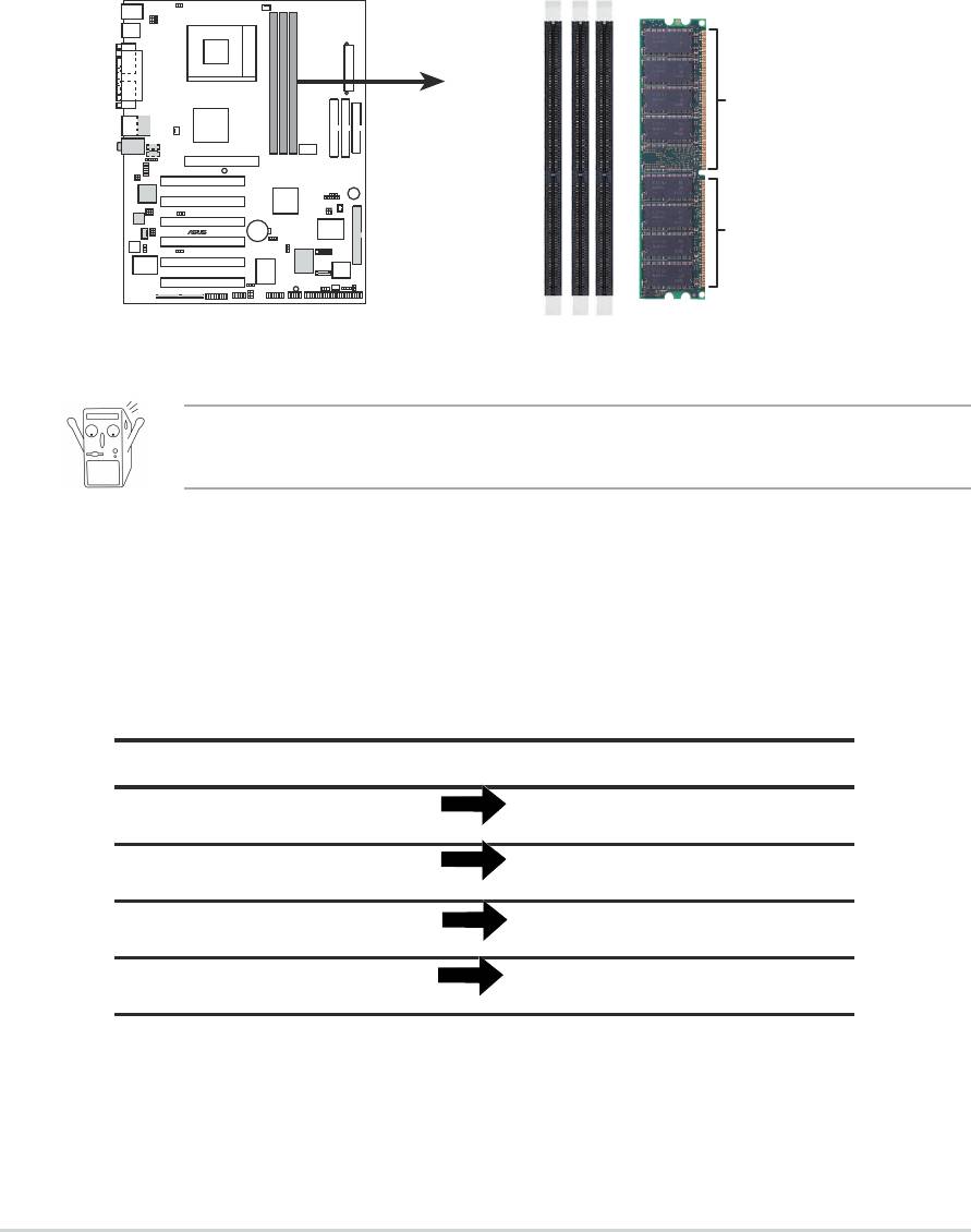
2.5 System memory
2.5.1 Overview
The motherboard comes with three Double Data Rate (DDR) Dual Inline
Memory Module (DIMM) sockets. These sockets support up to 3GB
system memory using 184-pin unbuffered non-ECC PC3200/PC2700/
2100/1600 DIMMs. (Note: DDR400 supports one (1) socket only. DDR333
supports two (2) sockets only.)
104 Pins
®
A7V8X
80 Pins
A7V8X 184-Pin DDR DIMM Sockets
A DDR DIMM is keyed with a notch so that it fits in only one direction.
DO NOT force a DIMM into a socket to avoid damaging the DIMM.
The DDR SDRAM technology evolved from the mainstream PC66, PC100,
PC133 memory known as Single Data Rate (SDR) SDRAM. DDR memory
however, has the ability to perform two data operations in one clock cycle,
thus providing twice the throughput of SDR memory. For example, a
200MHz DDR DIMM will support a 100MHz memory bus, and a 266MHz
DDR DIMM will support a 133MHz memory bus.
DDR Data Transfer Rate DDR Base Frequency
400MHz 200MHz
333MHz 166MHz
266MHz 133MHz
200MHz 100MHz
A DDR DIMM has the same physical dimensions as an SDR DIMM, but it
has a 184-pin footprint compared to the 168-pin of the SDR DIMM. Also, a
DDR DIMM is single notched while an SDR DIMM is double notched.
Therefore, a DDR DIMM is not backward compatible with SDR, and should
be installed only in a socket specially designed for DDR DIMMs.
2-6
Chapter 2: Hardware information
2.5.2 Memory configurations
You may install any DDR DIMMs with 64MB, 128MB, 256MB, 512MB, and
1GB densities into the DIMM sockets.
Use only the following combinations to install DDR DIMMs. Otherwise,
the system may not boot up.
DDR DIMM1 DDR DIMM2 DDR DIMM3
(Rows 0&1) (Rows 2&3) (Rows 4&5)
SS/DS SS/DS SS/DS
SS/DS SS/DS SS/DS
* SS - Single-sided DIMM
DS - Double-sided DIMM
2.5.3 DDR400 Qualified Vendor List
The following table lists the PC3200-DDR400 memory modules that have
been tested and qualified for use with this motherboard.
Vendor Model Size
Samsung M368L6423DTM-CC4 512MB
Samsung M368L3223DTM-CC4 256MB
Kingston KVR400X64C25/512 512MB
Currently, only one (1) DIMM slot supports DDR400 modules. Make sure
to use only the tested and qualified DDR400 DIMMs listed above. Other
DDR DIMMs manufactured by other vendors may not be suitable for this
motherboard. Visit the ASUS website (www.asus.com) for the latest
qualified vendor DDR400 module list.
ASUS A7V8X motherboard user guide
2-7
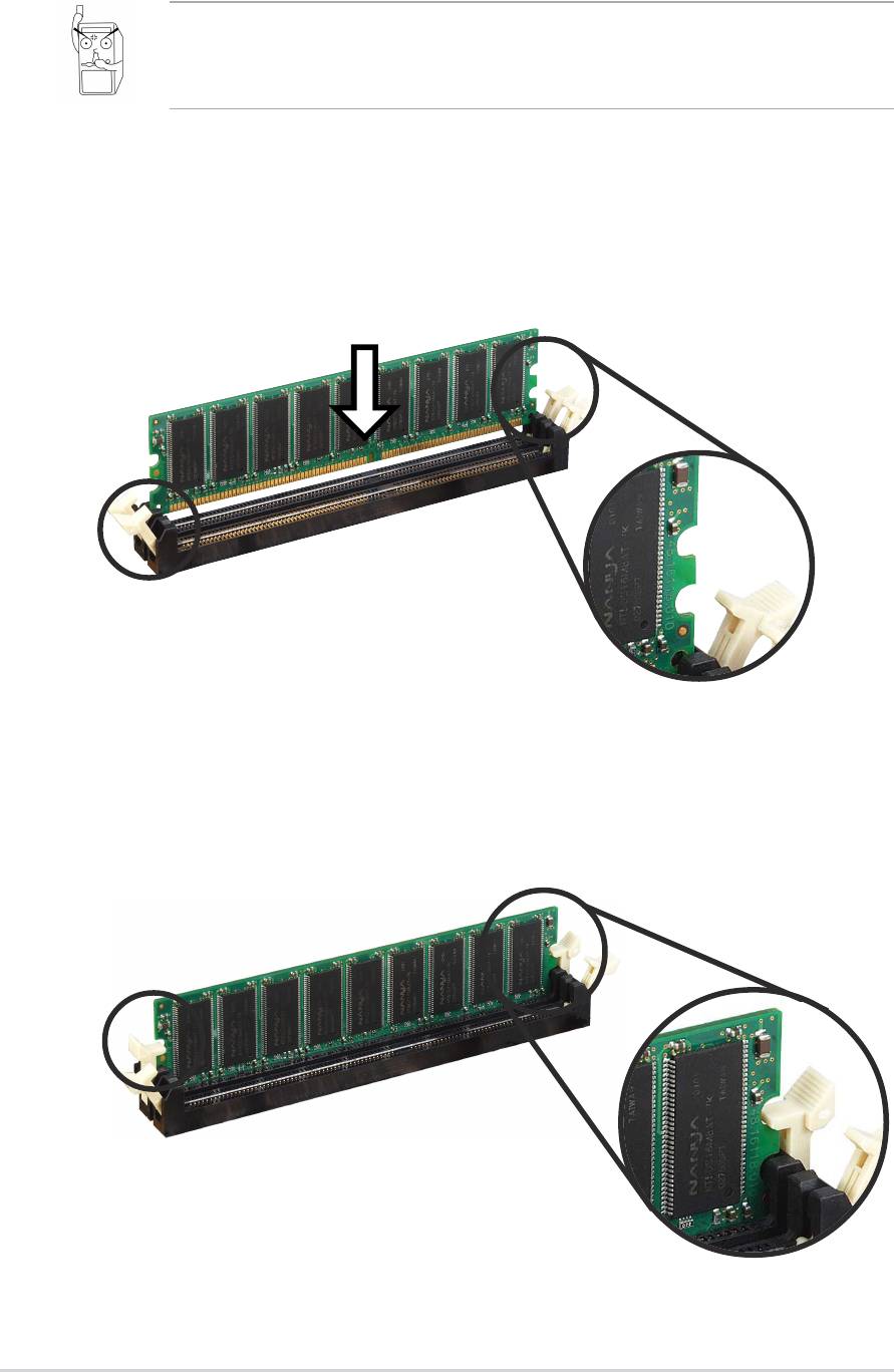
2.5.3 Installing a DIMM
Make sure to unplug the power supply before adding or removing
DIMMs or other system components. Failure to do so may cause
severe damage to both the motherboard and the components.
Follow these steps to install a DIMM.
1. Unlock a DIMM socket by pressing the retaining clips outward.
2. Align a DIMM on the socket such that the notch on the DIMM matches
the break on the socket.
Unlocked Retaining Clip
3. Firmly insert the DIMM into the socket until the retaining clips snap
back in place and the DIMM is properly seated.
Locked Retaining Clip
2-8
Chapter 2: Hardware information
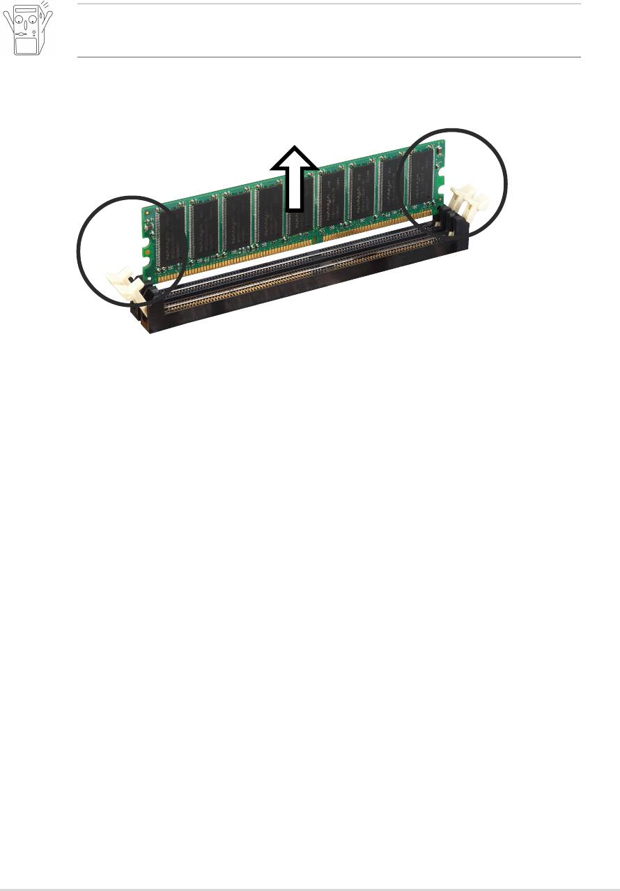
2.5.4 Removing a DIMM
Follow these steps to remove a DIMM.
1. Simultaneously press the retaining clips outward to unlock the DIMM.
Support the DIMM lightly with your fingers when pressing the retaining
clips. The DIMM might get damaged when it flips out with extra force.
2. Remove the DIMM from the socket.
ASUS A7V8X motherboard user guide
2-9
2-10
Chapter 2: Hardware information

2.6 Expansion slots
In the future, you may need to install expansion cards. The motherboard
has six PCI slots and one Accelerated Graphics Port (AGP) slot. The
following sub-sections describe the slots and the expansion cards that
they support.
Make sure to unplug the power cord before adding or removing
expansion cards. Failure to do so may cause you physical injury and
damage motherboard components.
2.6.1 Installing an expansion card
Follow these steps to install an expansion card.
1. Before installing the expansion card, read the documentation that
came with it and make the necessary hardware settings for the card.
2. Remove the system unit cover (if your motherboard is already installed
in a chassis).
3. Remove the bracket opposite the slot that you intend to use. Keep the
screw for later use.
4. Align the card connector with the slot and press firmly until the card is
completely seated on the slot.
5. Secure the card to the chassis with the screw you removed earlier.
6. Replace the system cover.
2.6.2 Configuring an expansion card
After installing the expansion card, configure the it by adjusting the
software settings.
1. Turn on the system and change the necessary BIOS settings, if any.
See Chapter 4 for information on BIOS setup.
2. Assign an IRQ to the card. Refer to the tables on the next page.
3. Install the software drivers for the expansion card.
ASUS A7V8X motherboard user guide
2-11

Standard Interrupt Assignments
IRQ Priority Standard Function
0 1 System Timer
1 2 Keyboard Controller
2 N/A Programmable Interrupt
3* 11 Communications Port (COM2)
4* 12 Communications Port (COM1)
5* 13 Sound Card (sometimes LPT2)
6 14 Floppy Disk Controller
7* 15 Printer Port (LPT1)
8 3 System CMOS/Real Time Clock
9* 4 ACPI Mode when used
10* 5 IRQ Holder for PCI Steering
11* 6 IRQ Holder for PCI Steering
12* 7 PS/2 Compatible Mouse Port
13 8 Numeric Data Processor
14* 9 Primary IDE Channel
15* 10 Secondary IDE Channel
* These IRQs are usually available for ISA or PCI devices.
IRQ assignments for this motherboard
ABCDEFGH
PCI slot 1 — — — shared — — — —
PCI slot 2 shared — — — — — — —
PCI slot 3 — shared — — — — — —
PCI slot 4 — — shared — — — — —
PCI slot 5 — — — shared — — — —
PCI slot 6 shared — — — — — — —
AGP slot shared — — — — — — —
USB 1.1 UHCI 1 — — — — — shared — —
USB 1.1 UHCI 2 — — — — — shared — —
USB 1.1 UHCI 3 — — — — — shared — —
USB 2.0 EHCI — — — — — shared — —
AC97 Codec — — — — — — used —
Onboard LAN — — shared — — — — —
Onboard 1394 — shared — — — — — —
Onboard SATA — shared — — — — — —
Onboard IDE — — — — used — — —
When using PCI cards on shared slots, ensure that the drivers support
“Share IRQ” or that the cards do not need IRQ assignments.
Otherwise, conflicts will arise between the two PCI groups, making the
system unstable and the card inoperable.
2-12
Chapter 2: Hardware information
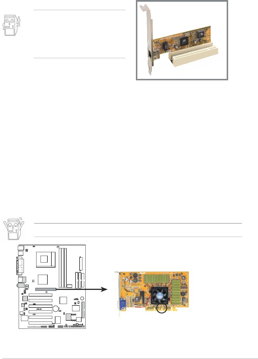
2.6.3 PCI slots
There are six 32-bit PCI slots in this motherboard. The slots support PCI
cards such as a LAN card, SCSI card, USB card, and other cards that
comply with PCI specifications. The following figure shows a LAN card
installed on a PCI slot.
The ASUS BlueMagic PCI slot
works as a normal PCI slot
and it is also compatible with
the ASUS proprietary wireless
card - SpaceLink B&W.
2.6.4 AGP slot
This motherboard has an Accelerated Graphics Port (AGP) slot that
supports +1.5V AGP cards. When you buy an AGP card, make sure that
you ask for one with +1.5V specification. Note the notches on the card
golden fingers to ensure that they fit the AGP slot on your motherboard.
If you installed an incorrect AGP card, such as a SiS305-based AGP card
or any other 3.3V AGP card, the onboard red LED (AGP_WARN1) lights
up, an indication that the card is not supported on the motherboard. As
long as this LED is lighted, you cannot turn on the system power even if
you press the power button, thus preventing permanent damage to the
motherboard.
Install only 1.5V AGP cards on this motherboard!
®
A7V8X
Keyed for 1.5v
A7V8X Accelerated Graphics Port (AGP)
ASUS A7V8X motherboard user guide
2-13
2.7 Jumpers
1. Keyboard power (3-pin KBPWR1)
This jumper allows you to enable or disable the keyboard wake-up
feature. Set this jumper to pins 2-3 (+5VSB) if you wish to wake up the
computer when you press a key on the keyboard (the default value is
[Disabled]). This feature requires an ATX power supply that can supply
at least 1A on the +5VSB lead, and a corresponding setting in the
BIOS (see section 4.5.1 Power Up Control).
KBPWR1
1
2
2
3
+5V
+5VSB
®
A7V8X
(Default)
A7V8X Keyboard Power Setting
2. V
CORE
over-voltage (3-pin OVER_VOLT1)
When enabled, this jumper allows CPU V
CORE
ranges of 1.7V to 2.05V.
When this jumper is disabled, V
CORE
setting has a range of +1.5V to
+1.85V. You may adjust the CPU V
CORE
through the BIOS Setup.
Setting to a very high core voltage may cause permanent damage to
the CPU. It is recommended that you keep the default setting
(Disable).
OVER_VOLT1
12 23
OVERVOLT
OVERVOLT
ENABLE
DISABLE
(Default)
®
A7V8X
A7V8X CPU Over Voltage Setting
2-14
Chapter 2: Hardware information
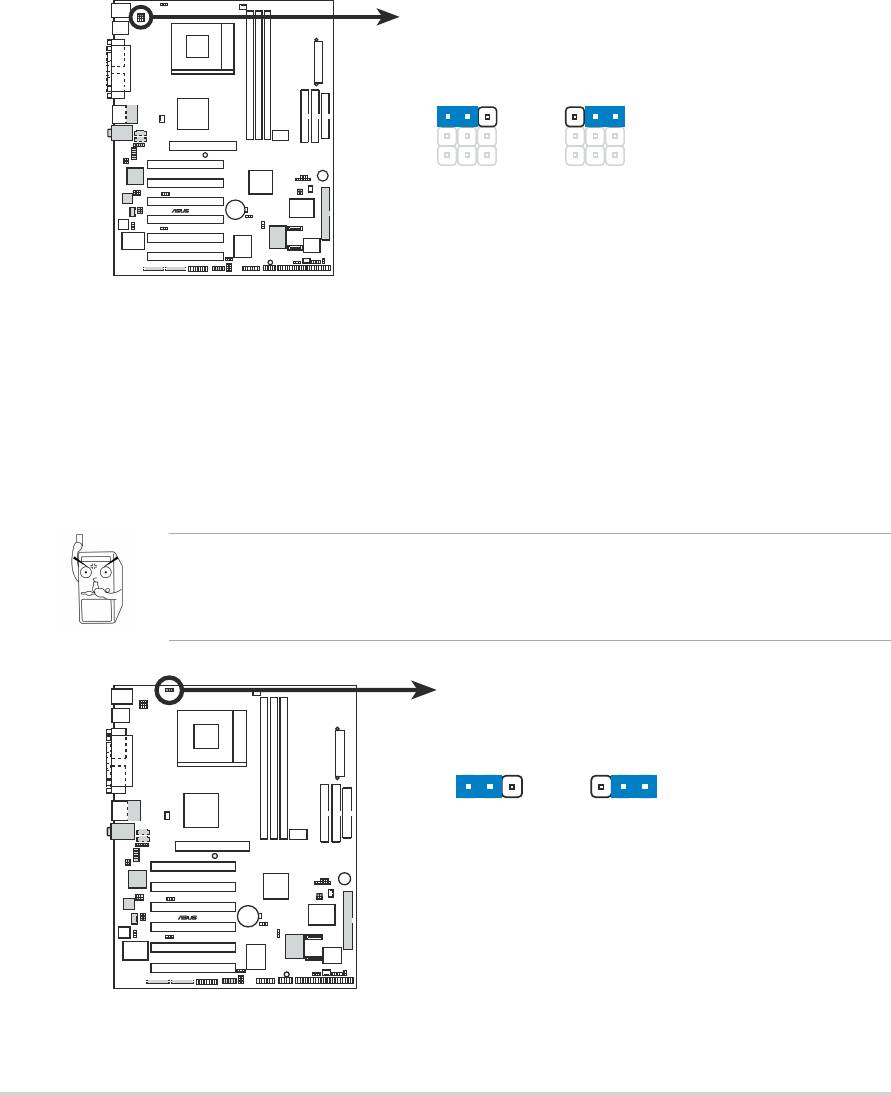
3. USB device wake-up (3-pin USBPWR_12, USBPWR_34,
USBPWR_56)
Set these jumpers to +5V to wake up the computer from S1 sleep
mode (CPU stopped, DRAM refreshed, system running in low power
mode) using the connected USB devices. Set to +5VSB to wake up
from S3 sleep mode (no power to CPU, DRAM in slow refresh, power
supply in reduced power mode). Both jumpers are set to pins 1-2 (+5V)
by default because not all computers have the appropriate power
supply to support this feature.
The USBPWR_12 and USBPWR_34 jumpers are for the rear USB
ports. The USBPWR_56 jumper is for the internal USB header that you
can connect to the front USB ports.
1. This feature requires a power supply that can provide at least 2A
on the +5VSB lead when these jumpers are set to +5VSB.
Otherwise, the system does not power up.
2. The total current consumed must NOT exceed the power supply
capability (+5VSB) whether under normal condition or in sleep
mode.
USBPWR_12
USBPWR_34
12
23
+5V
+5VSB
(Default)
®
A7V8X
USBPWR_56
12
23
+5V
+5VSB
A7V8X USB Device Wake Up
(Default)
ASUS A7V8X motherboard user guide
2-15
4. Clear RTC RAM (CLRTC1)
These jumpers allow you to clear the Real Time Clock (RTC) RAM in
CMOS. You can clear the CMOS memory of date, time, and system
setup parameters by erasing the CMOS RTC RAM data. The RAM
data in CMOS is powered by the onboard button cell battery.
To erase the RTC RAM:
1. Turn OFF the computer and unplug the power cord.
2. Remove the battery.
3. Short the jumper by replacing the jumper cap and removing it
after 3 seconds.
4. Re-install the battery.
5. Plug the power cord and turn ON the computer.
6. Hold down the <Del> key during the boot process and enter BIOS
setup to re-enter data.
CLRTC1
12 23
®
A7V8X
Clear CMOS
Normal
(Default)
A7V8X Clear RTC RAM
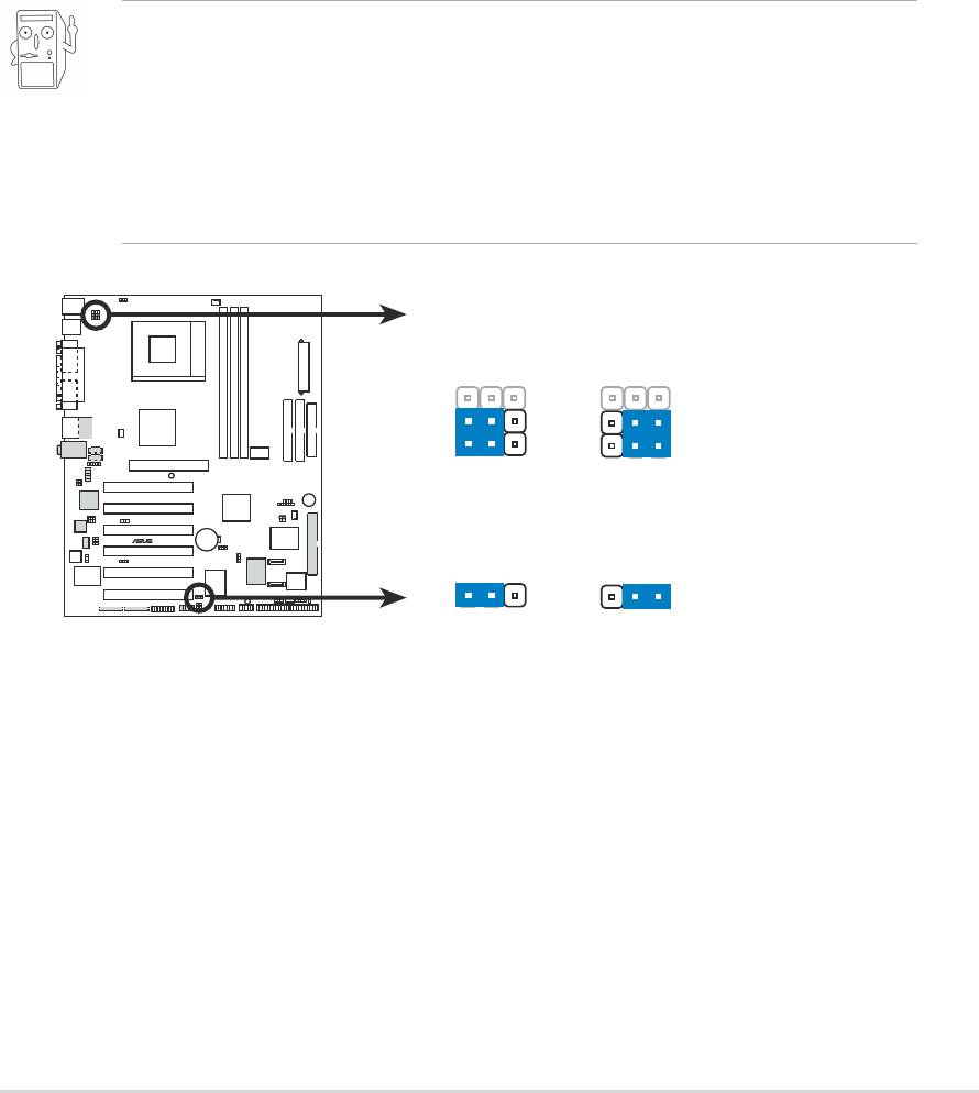
5. WPCI_USB Setting (6-pin WPCI_USB1)
This jumper connects one set of USB signal to PCI slot 6 to support
ASUS wireless card. Since USB signals are used by some reserved pins
of PCI slot and to ensure the compatibility of the other PCI cards, it should
be kept at default setting except when ASUS wireless card is used.
WPCI_USB1
6
5
4
3
4
3
®
A7V8X
2
1
Wireless
Original
PCI_USB
PCI
reserved pin
A7V8X WPCI_USB Setting
(Default)
2-16
Chapter 2: Hardware information
2.8 Connectors
This section describes and illustrates the internal connectors on the
motherboard.
Always connect ribbon cables with the red stripe to Pin 1 on the
connectors. Pin 1 is usually on the side closest to the power connector
on hard drives and CD-ROM drives, but may be on the opposite side
on floppy disk drives.
1. Hard disk activity LED (2-pin IDE_LED1)
This connector supplies power to the hard disk activity LED. The read
or write activities of any device connected to the primary or secondary
IDE connector cause this LED to light up.
®
A7V8X
IDELED1
TIP: If the case-mounted LED does not
A7V8X IDE Activity LED
light, try reversing the 2-pin plug.
2. Floppy disk drive connector (34-1 pin FLOPPY1)
This connector supports the provided floppy drive ribbon cable. After
connecting one end to the motherboard, connect the other end to the
floppy drive. (Pin 5 is removed to prevent incorrect insertion when
using ribbon cables with pin 5 plug).
FLOPPY1
®
A7V8X
PIN 1
NOTE: Orient the red markings on
the floppy ribbon cable to PIN 1.
A7V8X Floppy Disk Drive Connector
ASUS A7V8X motherboard user guide
2-17
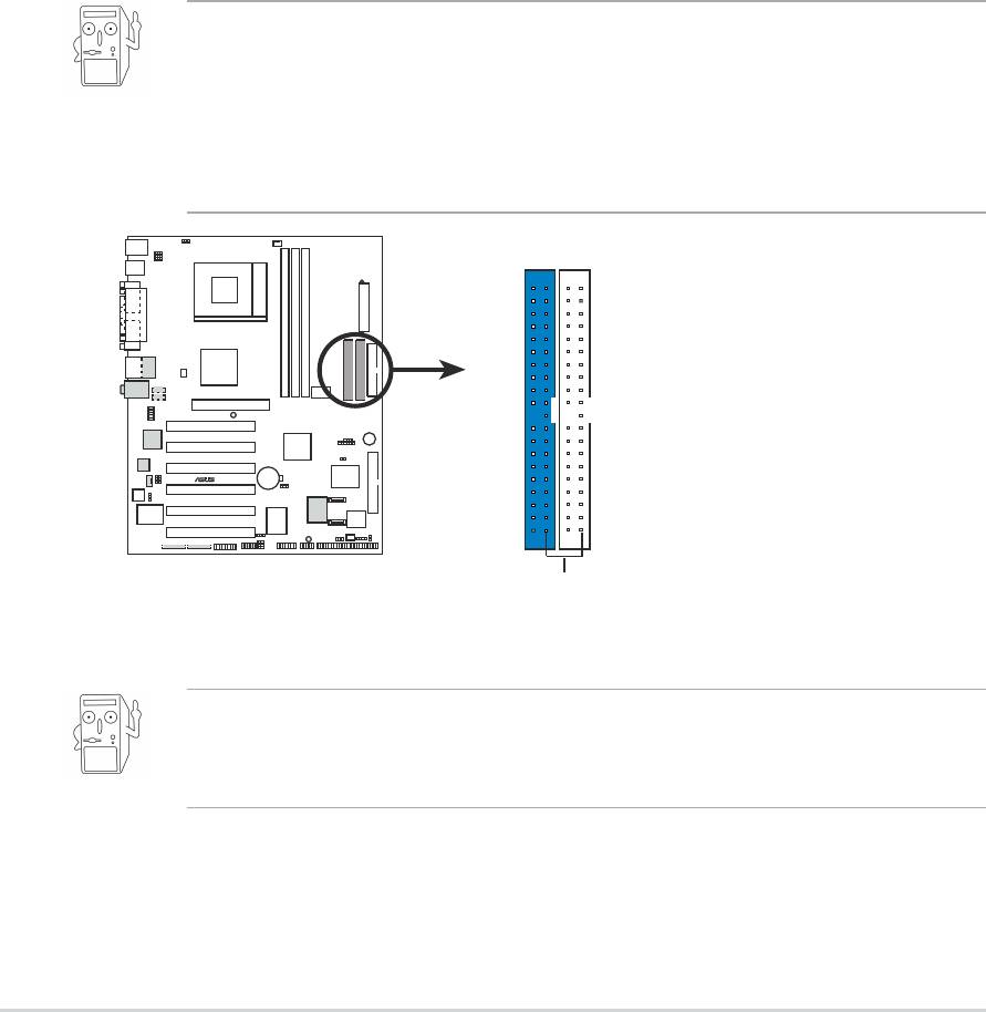
3. IDE connectors (40-1 pin IDE1, IDE2)
This connector supports the provided UltraDMA/133/100/66 IDE hard
disk ribbon cable. Connect the cable’s blue connector to the primary
(recommended) or secondary IDE connector, then connect the gray
connector to the UltraDMA/133/100/66 slave device (hard disk drive)
and the black connector to the UltraDMA/133/100/66 master device. It
is recommended that you connect non-UltraDMA/133/100/66 devices
to the secondary IDE connector. If you install two hard disks, you must
configure the second drive as a slave device by setting its jumper
accordingly. Refer to the hard disk documentation for the jumper
settings. BIOS supports specific device bootup. If you have more than
two UltraDMA/133/100/66 devices, purchase another UltraDMA/133/
100/66 cable. You may configure two hard disks to be both master
devices with two ribbon cables – one for the primary IDE connector
and another for the secondary IDE connector.
1. Pin 20 on each IDE connector is removed to match the covered
hole on the UltraDMA cable connector. This prevents incorrect
orientation when you connect the cables.
2. The hole near the blue connector on the UltraDMA/133/100/66
cable is intentional.
NOTE: Orient the red markings
(usually zigzag) on the IDE
ribbon cable to PIN 1.
®
A7V8X
PRI_IDE1
SEC_IDE1
A7V8X IDE Connectors
PIN 1
For UltraDMA/133/100/66 IDE devices, use an 80-conductor IDE
cable. The UltraDMA/66 cable included in the motherboard package
also supports UltraDMA/133/100.
2-18
Chapter 2: Hardware information
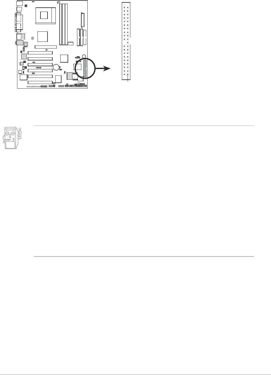
4. RAID ATA/133/100/66/33 connector (40-1 pin PRI_RAID)
This connector supports either RAID 0 or RAID 1 configuration through
the onboard Serial ATA controller chip. You can use the RAID feature to
set up a disk array configuration or to support additional IDE devices.
You can only install one hard disk (master mode) with this connector.
NOTE: Orient the red markings
(usually zigzag) on the IDE
ribbon cable to PIN 1.
®
A7V8X
PRI_RAID1
PIN 1
A7V8X PRI_RAID Connectors
Important notes on the RAID feature:
1. By default, the drives that you connect to the PRI_RAID
connectors follow the ATA133/100/66/33 protocol as
independent drives, not as a disk array.
2. The connector does not support ATAPI devices such as
CD-ROMs, DVD-ROMs, etc.
3. For RAID 1, you may choose any two connectors of Parallel
ATA and Serial ATA connectors. For RAID 0, you may choose
any two or three connectors of Parallel ATA and Serial ATA
connectors.
ASUS A7V8X motherboard user guide
2-19
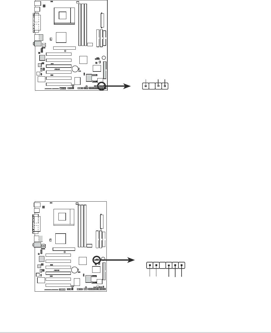
5. Chassis intrusion connector (4-1 pin CHASSIS1)
This lead is for a chassis designed with intrusion detection feature.
This requires an external detection mechanism such as a chassis
intrusion sensor or microswitch. When you remove any chassis
component, the sensor triggers and sends a high-level signal to this
lead to record a chassis intrusion event.
By default, the pins labeled “Chassis Signal” and “Ground” are shorted
with a jumper cap. If you wish to use the chassis intrusion detection
feature, remove the jumper cap from the pins.
CHASSIS1
®
A7V8X
+5VSB_MB
Chassis Signal
GND
A7V8X Chassis Alarm Lead
6. SMBus connector (6-1 pin SMB_CON1)
This connector allows you to connect SMBus (System Management
Bus) devices. Devices communicate with an SMBus host and/or other
SMBus devices using the SMBus interface. SMBus is a specific
2
implementation of an I
C bus, a multi-device bus that allows multiple
chips to connect to the same bus and enable each one to act as a
master by initiating data transfer.
SMB_CON1
®
A7V8X
1
+3V
Ground
SMBCLK
A7V8X SMBus Connector
FLOATING
SMBDATA
2-20
Chapter 2: Hardware information
7. ATX power connectors (20-pin ATXPWR1)
These connectors connect to an ATX 12V power supply. The plugs
from the power supply are designed to fit these connectors in only one
orientation. Find the proper orientation and push down firmly until the
connectors completely fit.
Make sure that your ATX 12V power supply can provide 8A on the
+12V lead and at least 1A on the +5-volt standby lead (+5VSB). The
minimum recommended wattage is 230W, or 300W for a fully
configured system. The system may become unstable and may
experience difficulty powering up if the power supply is inadequate.
ATXPWR1
+3.3VDC
+3.3VDC
-12.0VDC
+3.3VDC
COM
COM
PS_ON#
+5.0VDC
COM
COM
COM
+5.0VDC
COM
COM
®
A7V8X
-5.0VDC
PWR_OK
+5.0VDC
+5VSB
+5.0VDC
+12.0VDC
A7V8X ATX Power Connectors
8. Smart Card Reader connector (14-1 pin SMARTCON1)
This connector accommodates an optional Smart Card Reader that
allows you to conveniently make transactions such as financial, health
care, telephony, or traveling services through a Smart Card user
interface software.
SMARTCARD1
®
NC
NC
SCRREST
NC
SCIO
SCRRES#
A7V8X
1
NC
NC
VCC
GND
NC2
A7V8X Smartcard Connector
SCPWR#
SCRCLK
ASUS A7V8X motherboard user guide
2-21
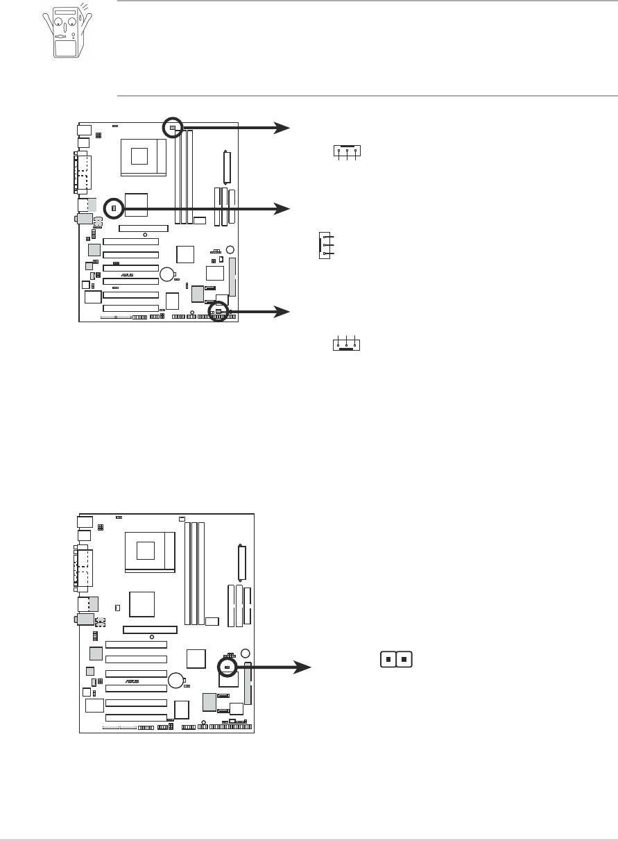
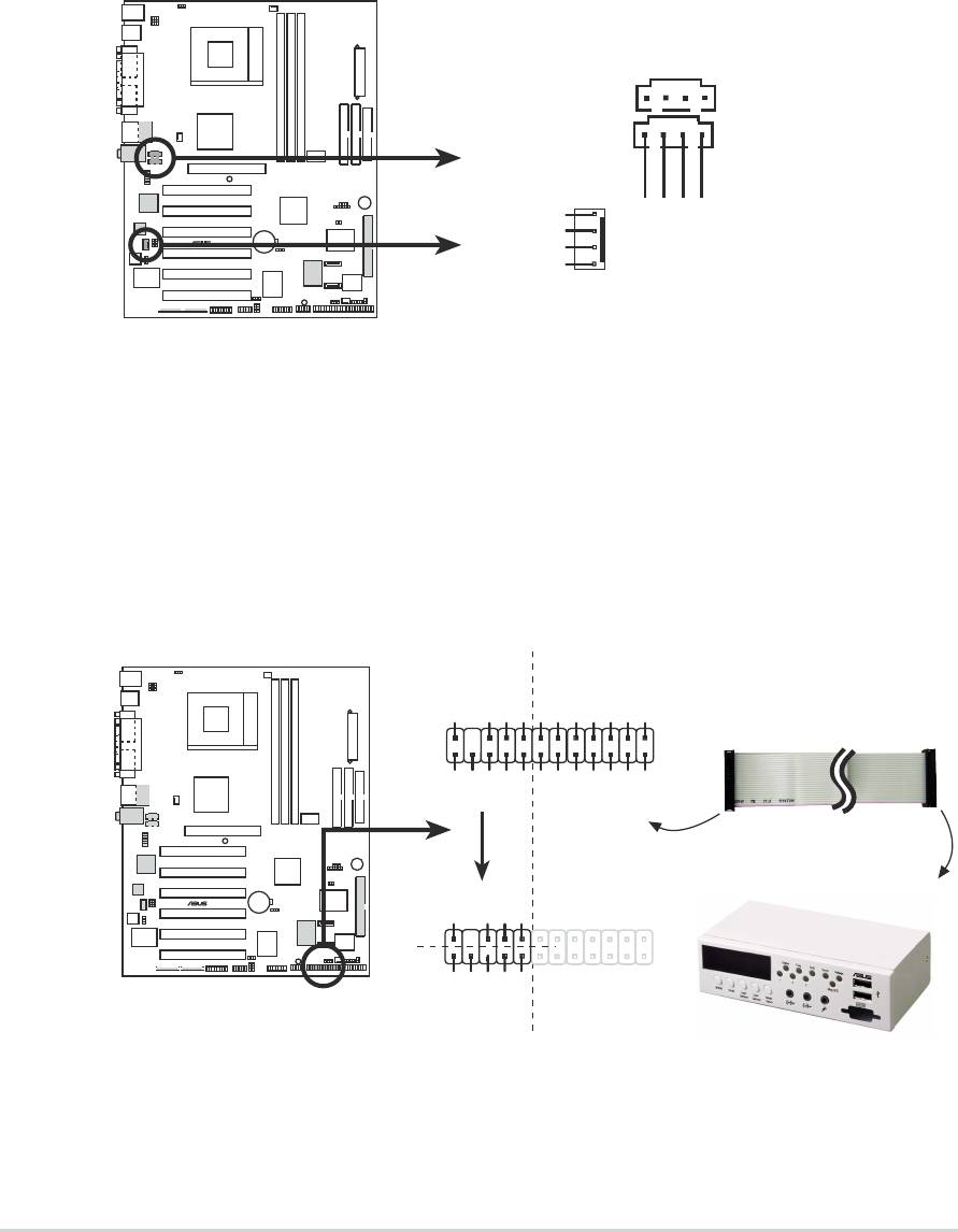
9. CPU, Chassis, and Power Fan Connectors
(3-pin CPU_FAN1, PWR_FAN1, CHA_FAN1)
The fan connectors support cooling fans of 350mA~740mA (8.88W
max.) or a total of 1A~2.22A (26.64W max.) at +12V. Connect the fan
cables to the fan connectors on the motherboard, making sure that the
black wire of each cable matches the ground pin of the connector.
Do not forget to connect the fan cables to the fan connectors. Lack of
sufficient air flow within the system may damage the motherboard
components. These are not jumpers! DO NOT place jumper caps on
the fan connectors!
CPU_FAN1
+12V
GND
Rotation
PWR_FAN1
GND
+12V
Rotation
®
A7V8X
CHA_FAN1
GND
+12V
Rotation
A7V8X 12-Volt Fan Connectors
10.Power supply thermal connector (2-pin TRPWR1)
If your power supply has a thermal monitoring feature, connect its
thermal sensor cable to this connector.
®
A7V8X
TRPWR1
Power Supply
Thermal Sensor
A7V8X Thermal Sensor Connector
2-22
Chapter 2: Hardware information
11. USB header (10-1 pin USB_56)
If the USB ports on the rear panel are inadequate, a USB header is
available for additional USB ports. The USB header complies with USB
2.0 specification that supports up to 480 Mbps connection speed. This
speed advantage over the conventional 12 Mbps on USB 1.1.
If your package came with a USB 2.0/GAME module, connect the USB
cable to this header. The module has two USB 2.0 ports that support
the next generation USB peripherals such as high resolution cameras,
scanners, and printers.
USB+5V
LDM5
LDP5
GND
NC
®
A7V8X
USB_56
(Blue)
1
LDM6
LDP6
GND
USB+5V
A7V8X USB 2.0 Header
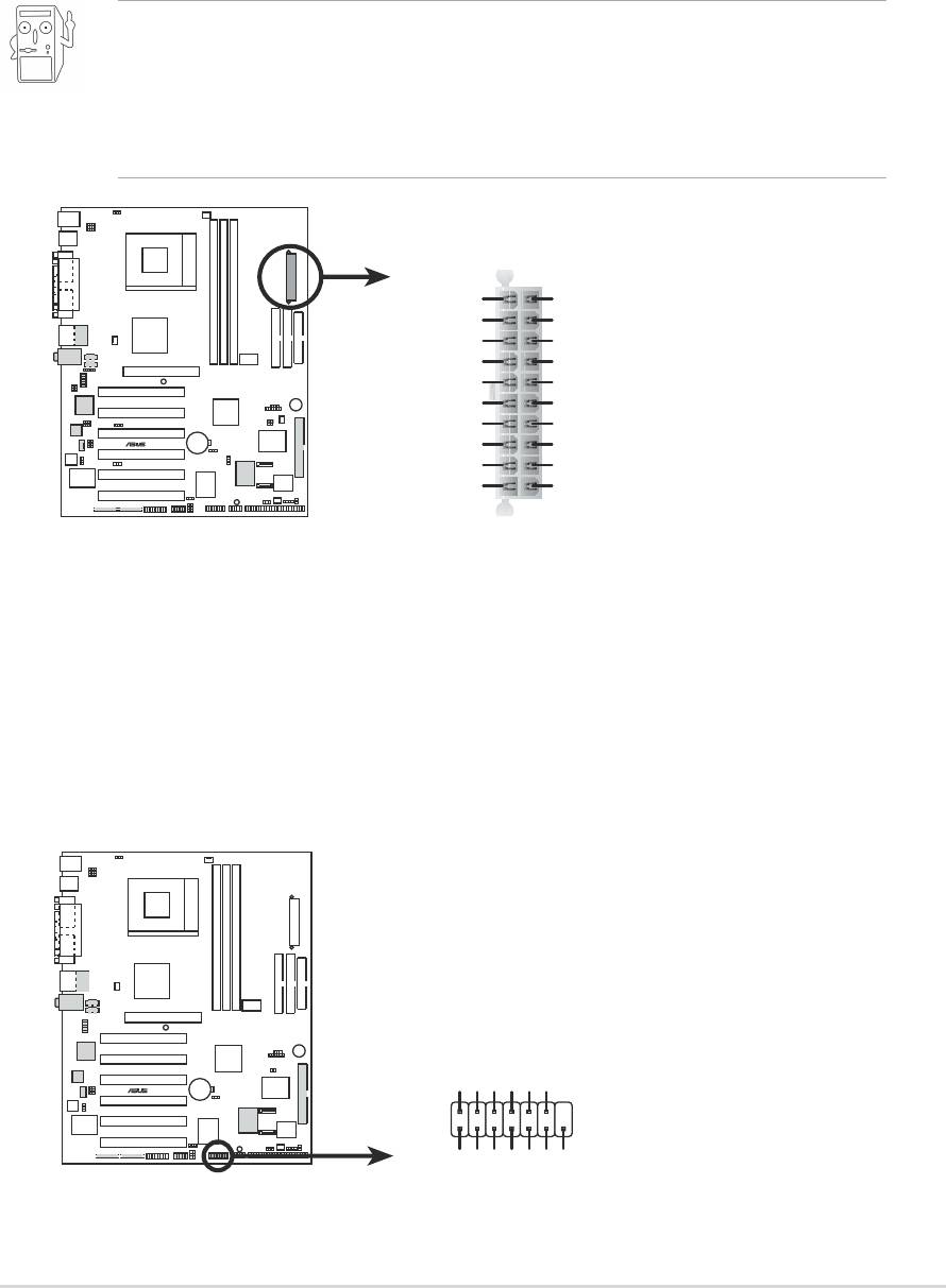
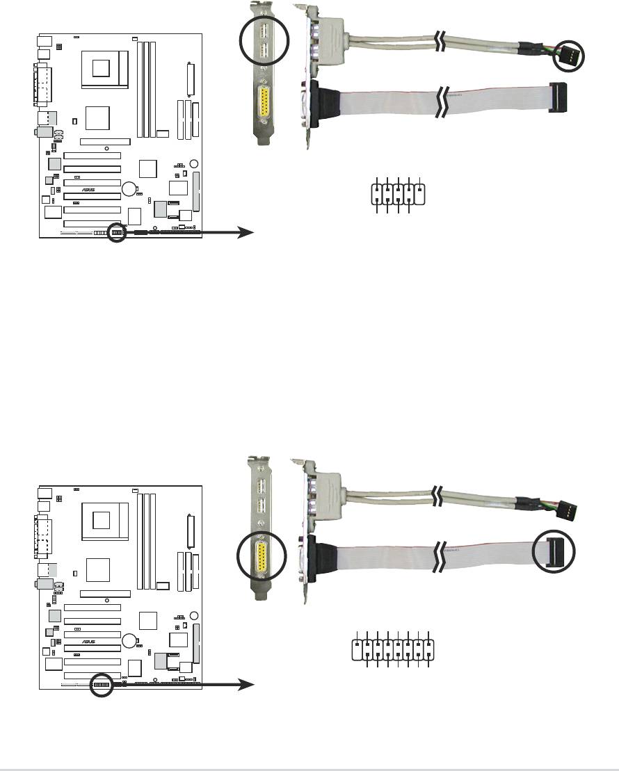
12.GAME/MIDI connector (16-1 pin GAME1) (on Audio model only)
This connector supports a GAME/MIDI module. If your package came
with the optional USB 2.0/GAME module, connect the GAME/MIDI
cable to this connector. The GAME/MIDI port on the module connects
a joystick or a game pad for playing games, and MIDI devices for
playing or editing audio files.
+5V
J1B2
J1CY
GND
GND
J1CX
J1B1
+5V
®
A7V8X
GAM1
+5V
J2B2
J2CY
J2CX
J2B1
MIDI_IN
A7V8X Game Connector
MIDI_OUT
ASUS A7V8X motherboard user guide
2-23
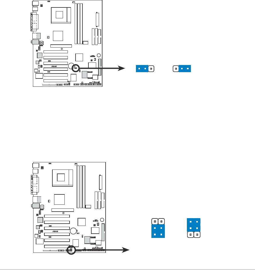
13.Internal audio connectors (4-pin CD1, AUX1, MODEM1)
(on audio models only)
These connectors allow you to receive stereo audio input from sound
sources such as a CD-ROM, TV tuner, or MPEG card. The MODEM
connector allows the onboard audio to interface with a voice modem
card with a similar connector. It also allows the sharing of mono_in
(such as a phone) and a mono_out (such as a speaker) between the
audio and a voice modem card.
AUX1(White)
CD1(Black)
MODEM1
Modem-In
Ground
®
A7V8X
Ground
Ground
Ground
Modem-Out
A7V8X Internal Audio Connectors
Left Audio Channel
Right Audio Channel
14.ASUS iPanel connector (24-1 pin AFPANEL1)
This connector allows you to connect an optional ASUS iPanel, an
easy-to-access drive bay with front I/O ports and status LEDs. If you
are not using an ASUS iPanel, you can connect an optional wireless
transmitting and receiving infrared module to the SIR connector.
AFPANEL1
+5 V
IRRX
GND
IRTX
SMBDATA
+3VSB
NC
NC
NC
NC
NC
NC
NC
+5V SMBCLK
NC
GND
BATT
+5VSB
MLED-
EXTSMI#
PCIRST#
CHASSIS#
Connect to AFPANEL Connector
®
Connect to iPanel
A7V8X
+5 V
IRRX
GND
IRTX
SIR
NC
NC
NC
GND
A7V8X iPanel Connector
+5VSB
IR_CON
2-24
Chapter 2: Hardware information
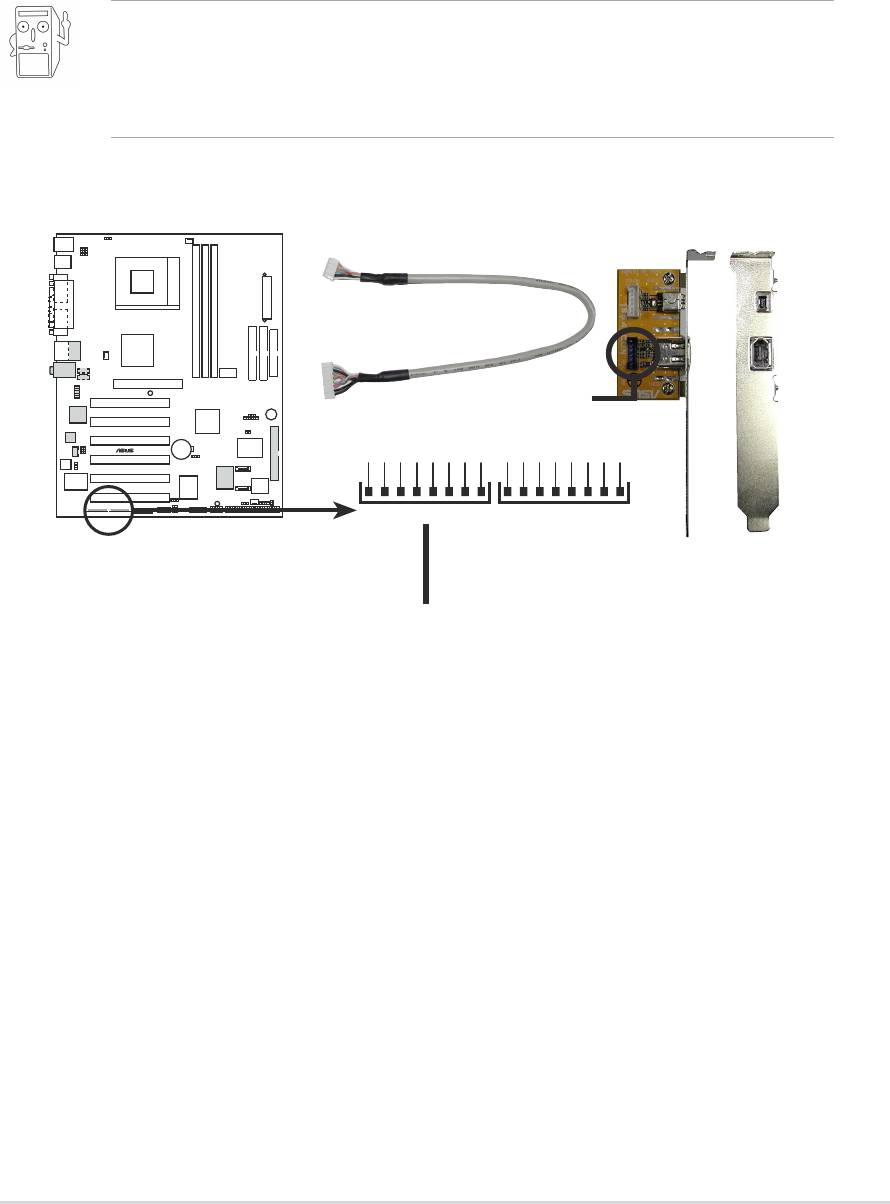
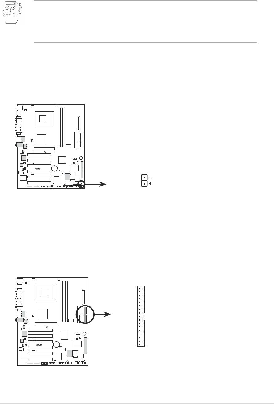
15.IEEE 1394 connector (8-1 pin IEEE1394_1, IEEE1394_2)
(on 1394 model only)
This connector accommodates two IEEE 1394 ports using a bundled
IEEE 1394 port bracket. Connect the bracket cable to this connector
then install the bracket into a slot opening at the back of the system
chassis.
Make sure to connect IEEE 1394 devices needing internal power
supply to the blue IEEE 1394 connector on-board (IEEEE1394_1). For
IEEE 1394 devices that doesn’t require internal power, you may
connect to the white IEEE 1394 connector (IEEE1394_2) on-board.
blue IEEE1394 connector
®
A7V8X
+12V
Ground
TPB-
TPB+
TPA-
TPA+
Ground
Ground
+12V
Ground
TPB-
TPB+
TPA-
TPA+
Ground
Ground
IEEE1394_1 IEEE1394_2
A7V8X IEEE-1394 Connectors
blue IEEE 1394 connector
ASUS A7V8X motherboard user guide
2-25
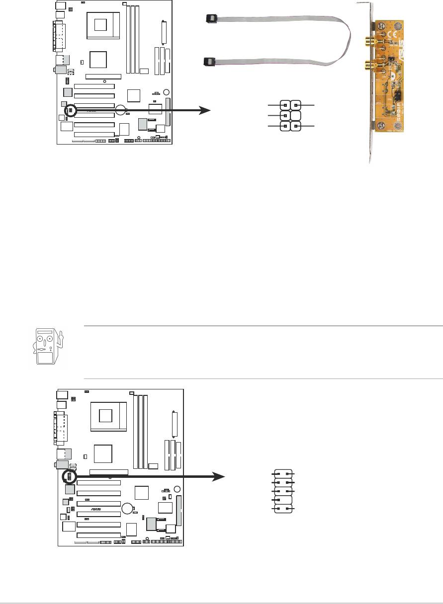
16.Digital audio connector (6-1 pin SPDIF1) (on audio models only)
This connector is for the bundled S/PDIF audio module that allows
digital instead of analog sound output. Connect one end of the audio
cable to the S/PDIF In/Out connector on the motherboard, and the
other end to the S/PDIF module.
SPDIF1
SPDIF_IN
GND
®
A7V8X
+5V
SPDIF_OUT
GND
1
A7V8X Digital Audio Connector
17.Front panel audio connector (10-1 pin FP_AUDIO1)
(on audio models only)
This is an interface for the Intel front panel audio cable that allow
convenient connection and control of audio devices.
Make sure to remove the caps from the Line out_R, BLINE_OUT_R,
Line out_L and BLINE_OUT_L jumpers if you installed the Intel front
panel audio cable.
FP_AUDIO1
MIC2
AGND
MICPWR +5VA
Line out_R
BLINE_OUT_R
NC
®
A7V8X
Line out_L
BLINE_OUT_L
A7V8X Front Panel Audio Connector
2-26
Chapter 2: Hardware information
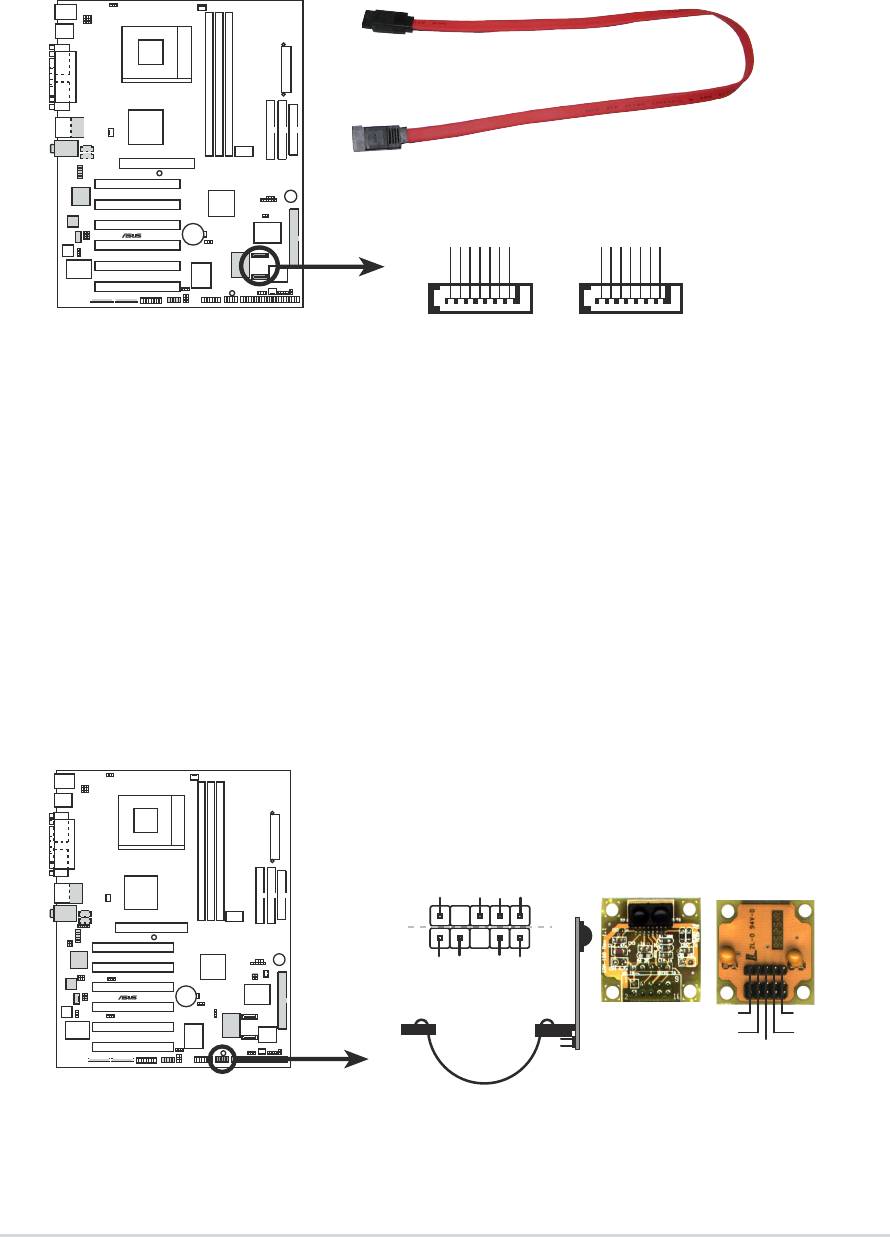
18. Serial ATA connector (7 pin PRI_SATA1, SEC_SATA1)
(on SATA model only)
These connectors accommodate the primary serial ATA (PRI_SATA1)
and a secondary serial ATA (SEC_SATA1) cables. Connect the serial
ATA cable to this connector then install to a serial ATA ready hard disk.
®
A7V8X
GND
RSATA_TXP2
RSATA_TXN2
GND
RSATA_RXP2
RSATA_RXN2
GND
GND
RSATA_TXP1
RSATA_TXN1
GND
RSATA_RXP1
RSATA_RXN1
GND
A7V8X SATA Connectors SEC_SATA1 PRI_SATA1
19.Infrared Module connector (10-1 or 10-2 pin SIR)
These connectors support an optional wireless transmitting and
receiving infrared module. The module mounts to a small opening on
the system chassis that support this feature. You must also configure
the UART2 Use As parameter in BIOS to set UART2 for use with IR.
Use the ten pins as shown in Back View and connect a ribbon cable
from the module to the motherboard SIR connector according to the
pin definitions.
Standard Infrared (SIR)
Front View Back View
+5V
IRRX
GND
IRTX
SIR
IRTX
GND
®
A7V8X
CIRRX
CIR+5V
IRTX
+5V
GND
(NC)
IRRX
A7V8X Infrared Module Connector
ASUS A7V8X motherboard user guide
2-27
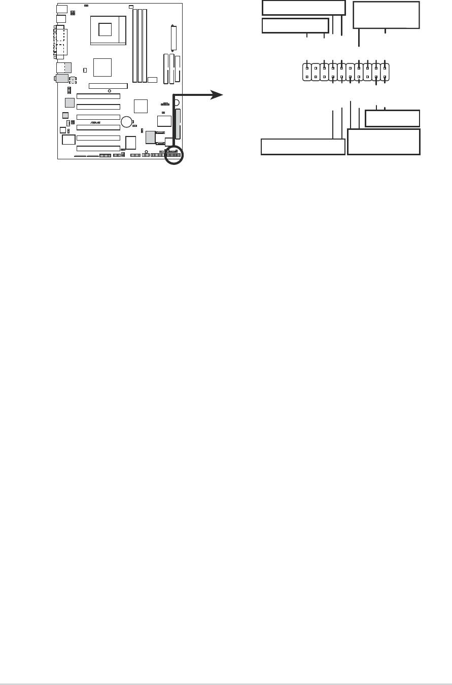
20.System panel connector (20-pin PANEL1)
This connector accommodates several system front panel functions.
Keyboard Lock
Speaker
Connector
Power LED
PLED+
PLED-
Keylock
Ground
+5V
Ground
Ground
Speaker
PWR
Ground
Ground
Reset
Ground
ExtSMI#
®
A7V8X
Reset SW
ATX Power
SMI Lead
Switch*
*
Requires an ATX power supply.
A7V8X System Panel Connectors
• System Power LED Lead (3-1 pin PLED)
This 3-1 pin connector connects to the system power LED. The LED
lights up when you turn on the system power, and blinks when the
system is in sleep mode.
• Keyboard Lock Lead (2-pin KEYLOCK)
This 2-pin connector connects to a chassis-mounted switch to allow
the use of the keyboard lock feature.
• System Warning Speaker Lead (4-pin SPKR)
This 4-pin connector connects to the case-mounted speaker and
allows you to hear system beeps and warnings.
• System Management Interrupt Lead (2-pin SMI)
This 2-pin connector allows you to manually place the system into a
suspend mode, or “green” mode, where system activity is instantly
decreased to save power and to expand the life of certain system
components. Attach the case-mounted suspend switch to this 2-pin
connector.
• ATX Power Switch/Soft-off Switch Lead (2-pin PWR)
This connector connects a switch that controls the system power.
Pressing the power switch turns the system between ON and SLEEP,
or ON and SOFT OFF, depending on the BIOS or OS settings.
Pressing the power switch while in the ON mode for more than 4
seconds turns the system OFF.
• Reset Switch Lead (2-pin RESET)
This 2-pin connector connects to the case-mounted reset switch for
rebooting the system without turning off the system power.
2-28
Chapter 2: Hardware information
