Asus P1-P5945GC: инструкция
Раздел: Компьютерная техника, комплектующие, аксессуары
Тип: Мультимедийный Компьютер

Инструкция к Мультимедийному Компьютеру Asus P1-P5945GC
English
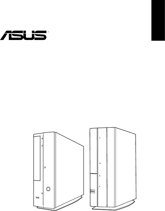
P-Series
ASUS PC (Desktop Barebone)
Installation manual
Download the latest manual from the ASUS website: www.asus.com
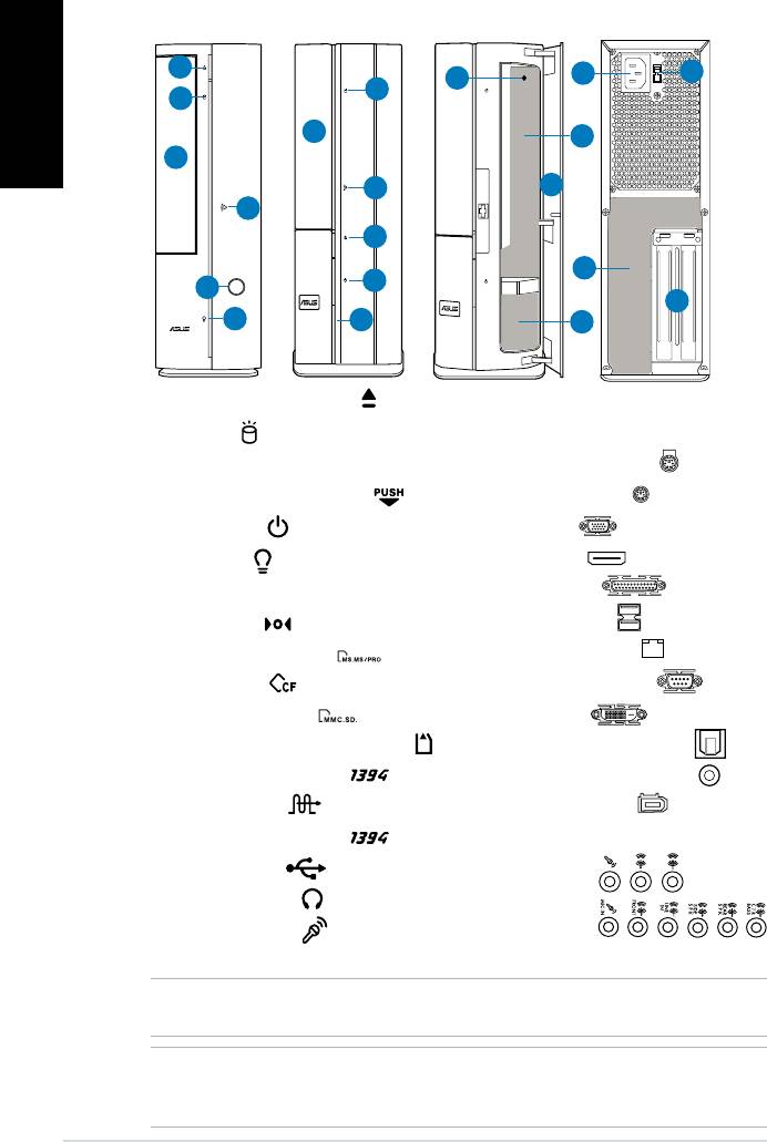
Front/Rear panel features
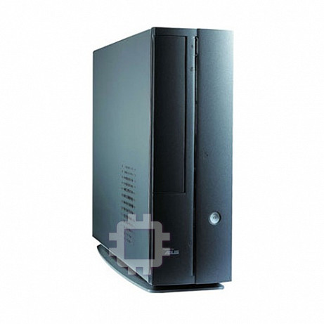
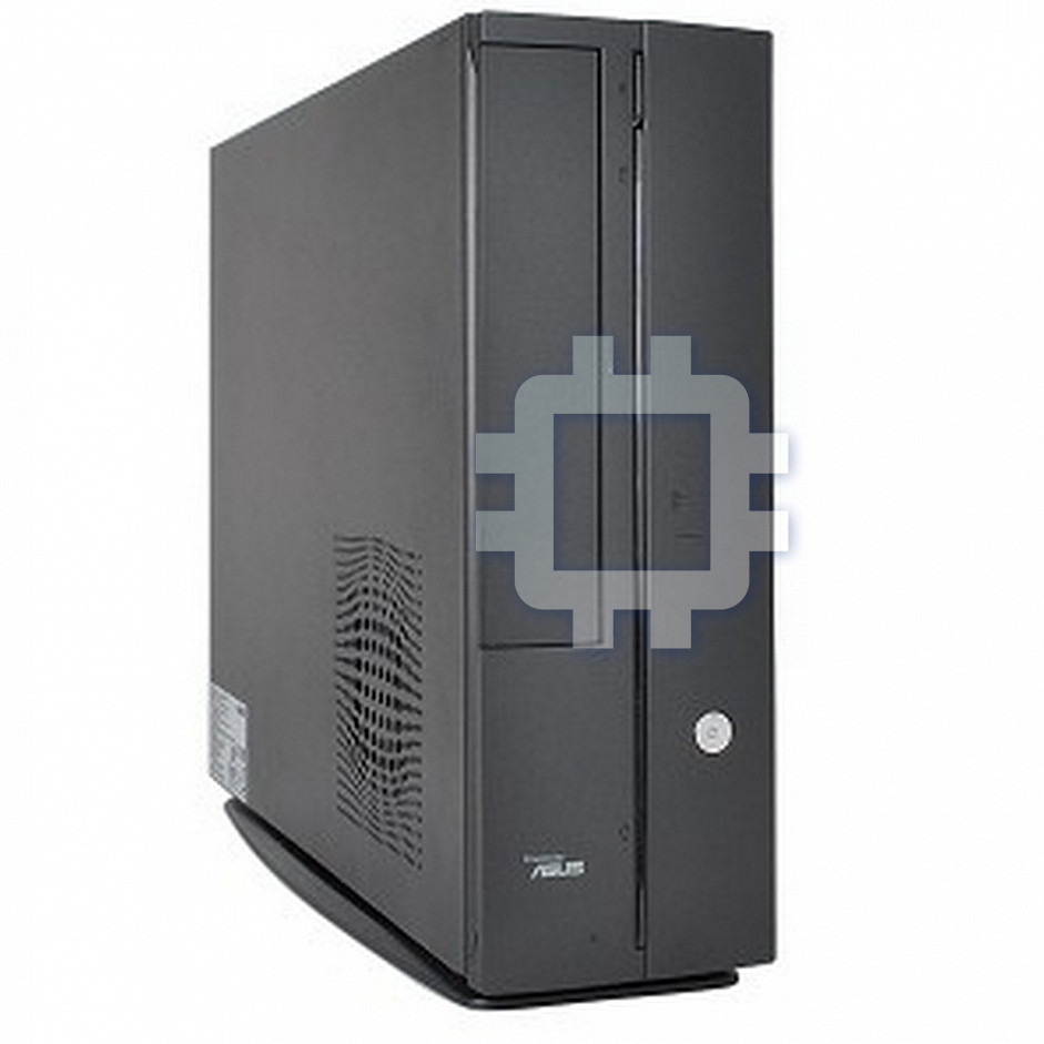
P1 Front (Close)
P2 Front (Close)
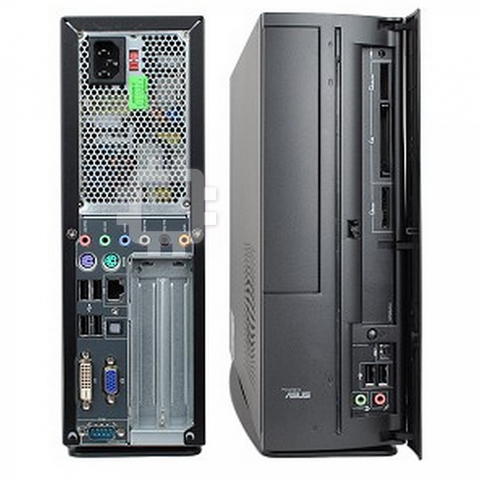
Front (Open)
Rear
English
1
11
12
8
2
2
3
9
3
4
7
4
1
13
5
5
14
6
6
10
1. Optical drive eject button ( )
11. Power connector
12.** Voltage selector switch
2. HDD LED (
)
3. Optical drive bay cover
13.* • PS/2 keyboard port (
)
4. Open the front panel cover (
)
• PS/2 mouse port (
)
• VGA port (
)
5. Power button ( )
• HDMI port (
)
6. Power LED (
)
• Parallel port (
)
7. Front panel cover
8. Reset button (
)
• USB 2.0 ports (
)
9.* • MS/MS Pro card slot (
)
• LAN (RJ-45) port (
)
• CF card slot (
)
• Serial (COM1) port (
)
• SD/MMC card slot (
)
• DVI-D port (
)
• MS/MS Pro/SD/MMC card slot (
)
• Optical S/PDIF Out port (
)
• 6-pin IEEE 1394a port (
)
• Coaxial S/PDIF Out port (
)
• S/PDIF In port (
)
• IEEE 1394a port (
)
10.* • 4-pin IEEE 1394a port (
)
•Audioportscongurations:
• USB 2.0 ports (
)
• 6-channel
• Headphone port (
)
• 8-channel
• Microphone port (
)
14. Expansion slot metal brackets
NOTE: *The front/rear panel slots/ports and their locations may vary, depending on the
model of your system. For detailed descriptions, refer to the system User Guide.
NOTE: **The system’s power supply unit has a 115V / 230V voltage selector switch
located beside the power connector. Use this switch to select the appropriate system
input voltage according to the voltage supply in your area.
2 Installation manual
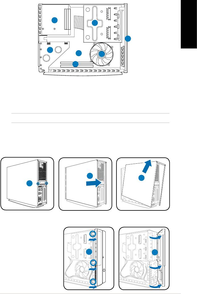
Internal components
3
2
English
1
4
5
7
6
1. Front panel cover
4. PCI card riser bracket (connected
2. 5.25-inch optical drive and
to the motherboard PCI slot)
3.5-inch hard disk drive cage
5. ASUS motherboard*
3. Power supply unit
6. DIMM sockets
7. CPU fan
NOTE: *Refer to the system User Guide for motherboard details.
Removing the cover
1. Remove the cover screws on the rear panel. Keep the screws for later use.
2. Pull the cover toward the rear panel.
3. Lift the cover, then set it aside.
2
3
Removing the front panel cover
1. Locate the front
panel cover hooks,
then lift them until
they disengage from
the chasis.
2. Swing the front panel
cover to the right,
remove it, and set it
aside.
3Installation manual
R
1
1
2
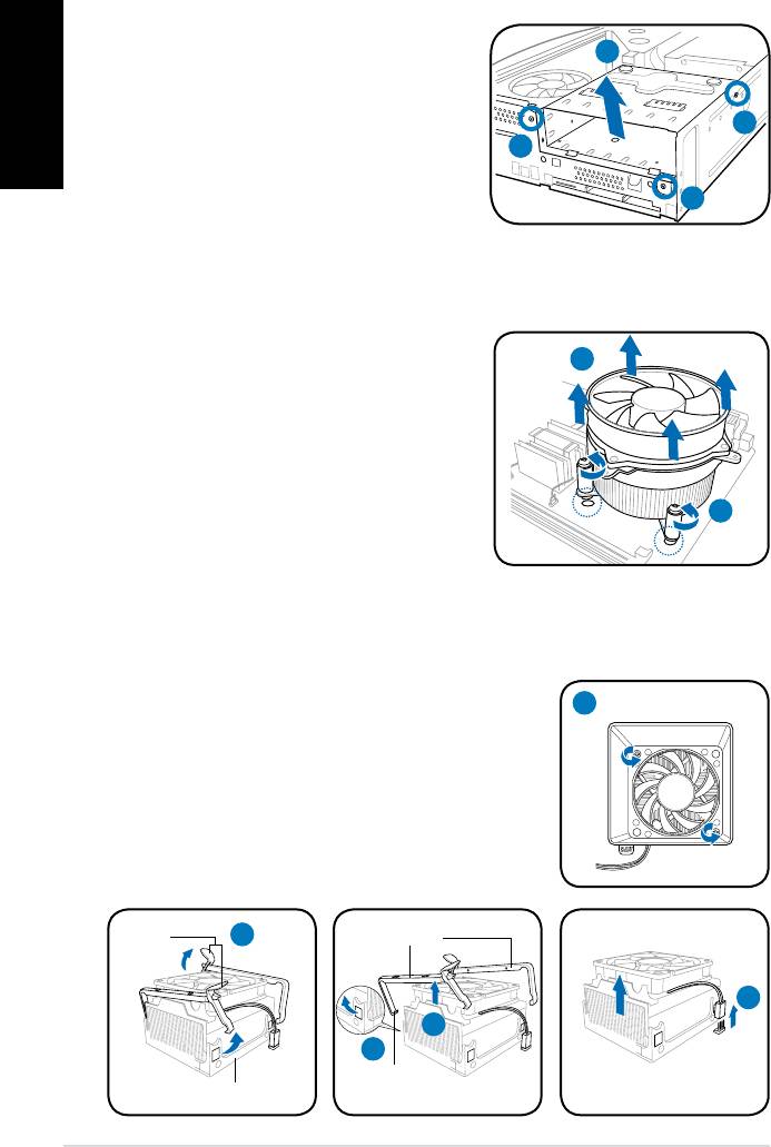
Removing the storage drive assembly
1. Lay the system on its side, then
English
locate and remove three storage
drive assembly screws.
2. Lift the storage drive assembly, then
set aside.
Removing the CPU fan and heatsink assembly
®
Removing an Intel
CPU fan and heatsink assembly
1. Disconnect the CPU fan cable from
the connector on the motherboard.
2. Loosen the four screws out of the
fan holes to disengage the fan
and heatsink assembly from the
motherboard.
3. Carefully remove the fan and
heatsink assembly, then set it aside.
Removing an AMD CPU fan and heatsink assembly
1. Remove two screws securing the blower to the CPU fan.
2. Carefully lift each locking lever and detach its end
from the hole of the retention module.
3. Release the hook of each metal clip from the hole
of the retention module.
4. Remove the metal clips from the side rail of the
fan and heatsink assembly.
5. Disconnect the CPU fan cable from the connector
on the motherboard, then remove the fan and
heatsink assembly.
4 Installation manual
2
1
1
1
3
2
1
Locking
2
Metal clip
levers
5
4
3
Hook
Retention module
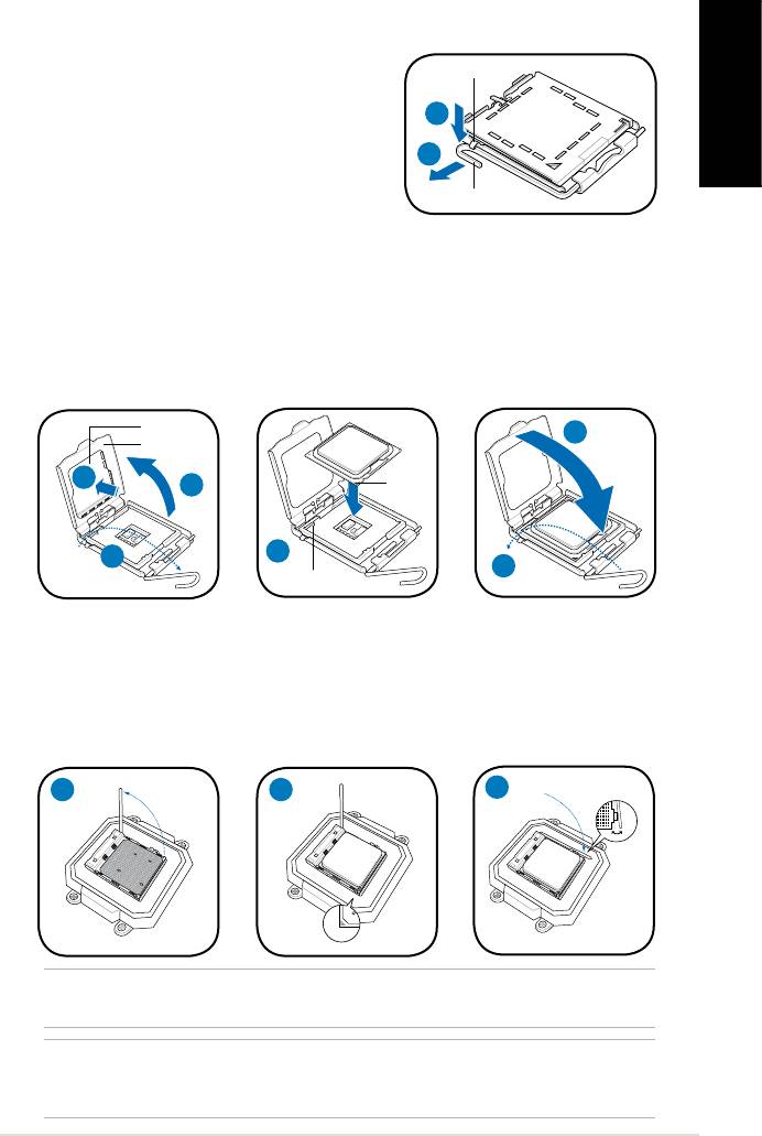
Installing a CPU
®
Installing an Intel
CPU in the LGA775 package
Retention tab
1. Locate the CPU socket on the motherboard.
2. Press the load lever with your thumb
2A
(2A), then move it to the left (2B) until it is
English
released from the retention tab.
2B
3. Lift the load lever in the direction of the
Load lever
arrow to a 135º angle.
4. Lifttheloadplatewithyourthumbandforengertoa100ºangle(4A),then
push the PnP cap from the load plate window to remove (4B).
5. Position the CPU over the socket, making sure that the gold triangle is on the
bottom-left corner of the socket. Fit the socket alignment key into the CPU
notch.
6. Close the load plate (6A), then push the load lever (6B) until it snaps into the
retention tab.
PnP cap
6A
Load plate
Gold
4B
4A
triangle
mark
5
3
6B
Alignment key
Installing an AMD CPU
1. Locate the CPU socket, then lift the socket lever to a 90º angle.
2. Install the CPU to the socket, making sure that the CPU corner with the gold
triangle matches the socket corner with a small triangle.
3. Push down the socket lever to secure the CPU.
1 2
3
®
NOTE: To reinstall an Intel
/ AMD CPU fan and heatsink assembly, follow the
instructions on page 4 in reverse order.
CAUTION: After you reinstall a fan and heatsink assembly, do not forget to connect
the CPU fan connector! Hardware monitoring error can occur if you fail to plug this
connector.
5Installation manual
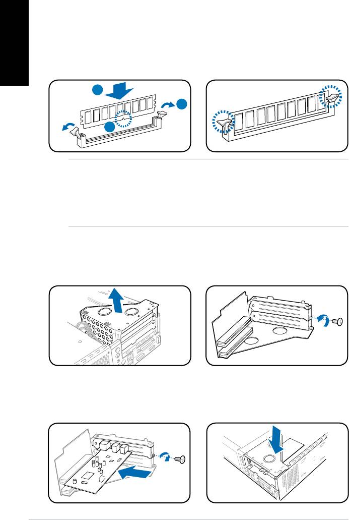
Installing a DIMM
1. Locate the DIMM sockets in the motherboard.
English
2. Unlock a DIMM socket by pressing the retaining clips outward.
3. Align a DIMM on the socket such that the notch on the DIMM matches the
break on the socket.
4. Push the DIMM to the socket until the retaining clips snap inward.
4
2
3
CAUTION:
• Unplug the power supply before adding or removing DIMMs. Failure to do so may
cause damage to the motherboard and/or components.
• ADDRDIMMiskeyedwithanotchsothatittsinonlyonedirection.Donotforce
a DIMM into a socket to avoid damaging the DIMM.
Installing an expansion card
1. Lift the PCI riser card assembly to
2. Remove the metal cover opposite
remove.
the slot that you intend to use.
3. Insert the card connector to the
4. Reinstall the PCI riser card
slot,thenpressthecardrmly
assembly. Make sure that the
untilittsinplace.Securethe
riser card connector sits properly
card with a screw.
on the motherboard PCI slot.
6 Installation manual
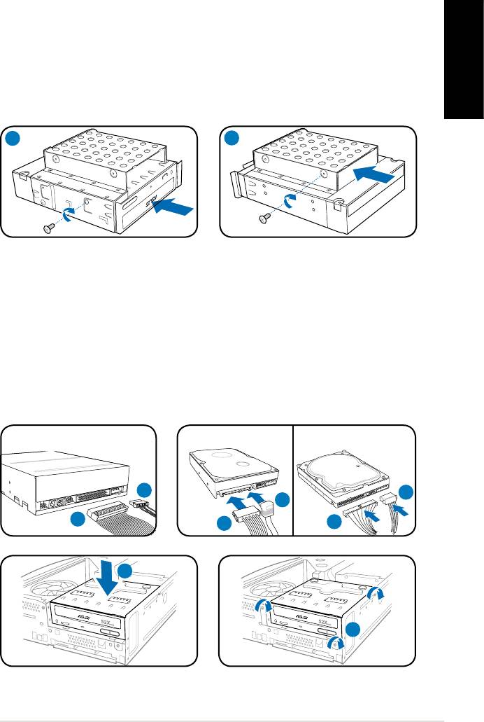
Installing optical and storage drives
1. Turn the storage drive assembly upside down with the 3.5-inch bay on top of
the 5.25-inch bay.
2. Insert the optical drive upside down to the 5.25-inch bay, then secure it with
two screws on both sides.
English
3. Turn the storage drive assembly, insert the hard disk drive upside down to the
3.5-inch bay, then secure it with two screws on both sides.
2
3
Reinstalling the storage drive assembly
1. Connect the IDE (1A) and power (1B) plugs to connectors at the back of the
optical drive.
2. Connect the SATA/IDE (2A) and power (2B) plugs to the connectors at the
back of the SATA/IDE hard disk drives.
3. Install the storage drive assembly to the chassis.
4. Secure the storage drive assembly with three screws.
SATA
IDE
1B
2B
2A
1A
2B
2A
7Installation manual
R
3
R
4
Installing the foot stand
1. Insert the foot stand hooks into
2. Pull the foot stand to the direction
English
the holes on the chassis.
of the arrow until the lock snaps
in place.
NOTE: To remove the foot stand, lift the lock, then slightly push the foot stand to the
direction of the rear panel until it disengages from the chassis.
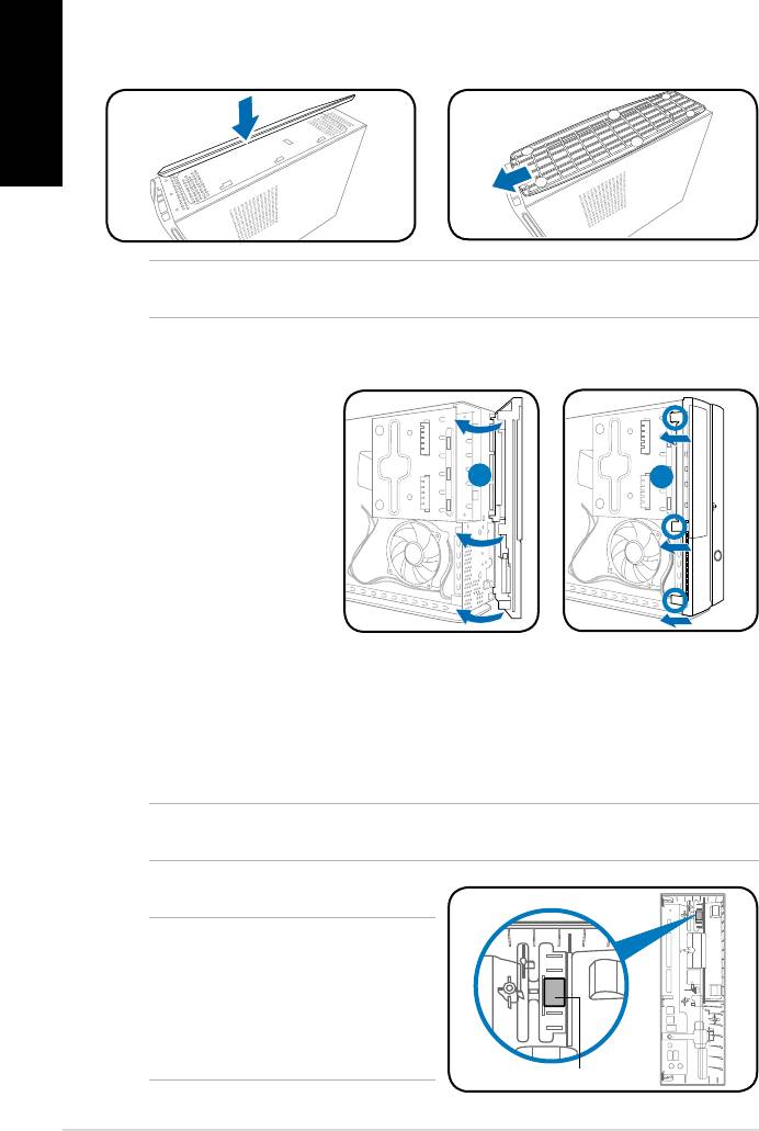
Reinstalling the front panel cover
Reinstalling the cover
1. Insertthecovertothechasis.Makesurethecovertabstthechasisrails.
2. Pushthecovertowardthefrontpaneluntilittsinplace.
3. Secure the cover with two screws you removed earlier.
NOTE: Refer to the pictures in the section “Removing the cover” on page 3 in reverse
order.
NOTE: For P2 model, if your optical
drive tray fails to eject when you press
the eject button, attach the provided
sticker to the location shown at the back
of the front panel cover. Make sure the
sticker aligns with the optical drive eject
button.
8 Installation manual
R
1. Insert the front panel
cover tabs to the holes
on the right side of the
chassis, then swing
1
2
the front panel cover to
the left.
2. Insert the front panel
cover hooks to the
chassis until the front
panelcovertsin
place.
Sticker


