Asus A7V600: инструкция
Раздел: Бытовая, кухонная техника, электроника и оборудование
Тип: Компьютерные аксессуары
Инструкция к Компьютерным аксессуарам Asus A7V600

A7V400-MX SE
Motherboard

E1942E1942
E1942E1942
E1942
First edition V1
February 2005
Copyright © 2005 ASUSTeK COMPUTER INC. All Rights Reserved.
Copyright © 2005 ASUSTeK COMPUTER INC. All Rights Reserved.Copyright © 2005 ASUSTeK COMPUTER INC. All Rights Reserved.
Copyright © 2005 ASUSTeK COMPUTER INC. All Rights Reserved.Copyright © 2005 ASUSTeK COMPUTER INC. All Rights Reserved.
No part of this manual, including the products and software described in it, may be reproduced,
transmitted, transcribed, stored in a retrieval system, or translated into any language in any form
or by any means, except documentation kept by the purchaser for backup purposes, without the
express written permission of ASUSTeK COMPUTER INC. (“ASUS”).
Product warranty or service will not be extended if: (1) the product is repaired, modified or
altered, unless such repair, modification of alteration is authorized in writing by ASUS; or
(2) the serial number of the product is defaced or missing.
ASUS PROVIDES THIS MANUAL “AS IS” WITHOUT WARRANTY OF ANY KIND, EITHER EXPRESS OR
IMPLIED, INCLUDING BUT NOT LIMITED TO THE IMPLIED WARRANTIES OR CONDITIONS OF
MERCHANTABILITY OR FITNESS FOR A PARTICULAR PURPOSE. IN NO EVENT SHALL ASUS, ITS
DIRECTORS, OFFICERS, EMPLOYEES OR AGENTS BE LIABLE FOR ANY INDIRECT, SPECIAL,
INCIDENTAL, OR CONSEQUENTIAL DAMAGES (INCLUDING DAMAGES FOR LOSS OF PROFITS, LOSS
OF BUSINESS, LOSS OF USE OR DATA, INTERRUPTION OF BUSINESS AND THE LIKE), EVEN IF ASUS
HAS BEEN ADVISED OF THE POSSIBILITY OF SUCH DAMAGES ARISING FROM ANY DEFECT OR
ERROR IN THIS MANUAL OR PRODUCT.
SPECIFICATIONS AND INFORMATION CONTAINED IN THIS MANUAL ARE FURNISHED FOR
INFORMATIONAL USE ONLY, AND ARE SUBJECT TO CHANGE AT ANY TIME WITHOUT NOTICE, AND
SHOULD NOT BE CONSTRUED AS A COMMITMENT BY ASUS. ASUS ASSUMES NO RESPONSIBILITY
OR LIABILITY FOR ANY ERRORS OR INACCURACIES THAT MAY APPEAR IN THIS MANUAL,
INCLUDING THE PRODUCTS AND SOFTWARE DESCRIBED IN IT.
Products and corporate names appearing in this manual may or may not be registered
trademarks or copyrights of their respective companies, and are used only for identification or
explanation and to the owners’ benefit, without intent to infringe.
iiii
ii
iiii

Contents
Notices ................................................................................................. v
Safety information .............................................................................. vi
About this guide ................................................................................ vii
A7V400-MX SE specifications summary ........................................... viii
Chapter 1:Chapter 1:
Chapter 1:Chapter 1:
Chapter 1:
Product introduction
Product introductionProduct introduction
Product introductionProduct introduction
1.1 Welcome! .............................................................................. 1-2
1.2 Package contents ................................................................. 1-2
1.3 Special features .................................................................... 1-2
1.3.1 Product highlights................................................... 1-2
1.3.2 Innovative ASUS features ....................................... 1-4
1.4 Before you proceed .............................................................. 1-5
1.5 Motherboard overview .......................................................... 1-6
1.5.1 Motherboard layout ................................................ 1-6
1.5.2 Placement direction ................................................ 1-7
1.5.3 Screw holes ............................................................ 1-7
1.6 Central Processing Unit (CPU) .............................................. 1-8
1.6.1 Overview ................................................................. 1-8
1.6.2 Installing the CPU.................................................... 1-8
1.7 System memory ................................................................... 1-9
1.7.1 Overview ................................................................. 1-9
1.7.2 Memory configurations ........................................... 1-9
1.7.3 Installing a DIMM ................................................... 1-13
1.7.4 Removing a DIMM ................................................. 1-13
1.8 Expansion slots ................................................................... 1-14
1.8.1 Installing an expansion card .................................. 1-14
1.8.2 Configuring an expansion card.............................. 1-14
1.8.3 AGP slot ................................................................ 1-16
1.8.4 PCI slots ................................................................ 1-16
1.9 Switch and jumpers ............................................................ 1-17
1.10 Connectors ......................................................................... 1-20
1.10.1 Rear panel connectors .......................................... 1-20
1.10.2 Internal connectors............................................... 1-21
iiiiii
iii
iiiiii

Contents
Safeguards
Chapter 2:Chapter 2:
Chapter 2:Chapter 2:
Chapter 2:
BIOS setupBIOS setup
BIOS setupBIOS setup
BIOS setup
2.1 Managing and updating your BIOS ........................................ 2-2
2.1.1 Creating a bootable floppy disk .............................. 2-2
2.1.2 AwardBIOS Flash Utility .......................................... 2-3
2.1.3 ASUS CrashFree BIOS utility ................................... 2-4
2.1.4 ASUS EZ Flash utility .............................................. 2-4
2.1.5 ASUS Update utility ................................................ 2-5
2.2 BIOS beep codes .................................................................. 2-7
2.3 BIOS setup program ............................................................. 2-7
2.3.1 BIOS menu bar ........................................................ 2-8
2.3.2 Legend bar ............................................................. 2-8
2.4 Main menu .......................................................................... 2-10
2.5 Advanced menu .................................................................. 2-15
2.5.1 CPU Configuration ................................................. 2-15
2.5.2 Memory Configuration .......................................... 2-16
2.5.3 Chipset ................................................................. 2-17
2.5.4 PCIPnP ................................................................... 2-19
2.5.5 Onboard Devices Configuration ............................ 2-20
2.5.6 USB Configuration................................................. 2-22
2.6 Power menu ........................................................................ 2-23
2.6.1 APM Configuration ................................................ 2-24
2.6.2 Hardware Monitor ................................................. 2-26
2.7 Boot menu .......................................................................... 2-27
2.7.1 Boot Device Priority .............................................. 2-27
2.7.2 Removable Drives ................................................. 2-28
2.7.3 Hard Disk Drives ................................................... 2-28
2.7.4 CDROM Drives ....................................................... 2-29
2.7.5 Boot Settings Configuration ................................. 2-29
2.7.6 Security ................................................................ 2-30
2.8 Exit menu ........................................................................... 2-32
Chapter 3:Chapter 3:
Chapter 3:Chapter 3:
Chapter 3:
Software supportSoftware support
Software support
Software supportSoftware support
3.1 Installing an operating system ............................................. 3-2
3.2 Support CD information ........................................................ 3-2
3.2.1 Running the support CD ......................................... 3-2
3.2.2 Drivers menu .......................................................... 3-3
3.2.3 Utilities menu .......................................................... 3-3
3.2.4 Contacts menu ....................................................... 3-4
iviv
iv
iviv

Notices
Federal Communications Commission Statement
Federal Communications Commission StatementFederal Communications Commission Statement
Federal Communications Commission StatementFederal Communications Commission Statement
This device complies with FCC Rules Part 15. Operation is subject to the
following two conditions:
• This device may not cause harmful interference, and
• This device must accept any interference received including
interference that may cause undesired operation.
This equipment has been tested and found to comply with the limits for a
Class B digital device, pursuant to Part 15 of the FCC Rules. These limits
are designed to provide reasonable protection against harmful interference
in a residential installation. This equipment generates, uses and can radiate
radio frequency energy and, if not installed and used in accordance with
manufacturer’s instructions, may cause harmful interference to radio
communications. However, there is no guarantee that interference will not
occur in a particular installation. If this equipment does cause harmful
interference to radio or television reception, which can be determined by
turning the equipment off and on, the user is encouraged to try to correct
the interference by one or more of the following measures:
• Reorient or relocate the receiving antenna.
• Increase the separation between the equipment and receiver.
• Connect the equipment to an outlet on a circuit different from that to
which the receiver is connected.
• Consult the dealer or an experienced radio/TV technician for help.
The use of shielded cables for connection of the monitor to the graphics
card is required to assure compliance with FCC regulations. Changes or
modifications to this unit not expressly approved by the party
responsible for compliance could void the user’s authority to operate
this equipment.
Canadian Department of Communications Statement
Canadian Department of Communications StatementCanadian Department of Communications Statement
Canadian Department of Communications StatementCanadian Department of Communications Statement
This digital apparatus does not exceed the Class B limits for radio noise
emissions from digital apparatus set out in the Radio Interference
Regulations of the Canadian Department of Communications.
This class B digital apparatus complies with Canadian
This class B digital apparatus complies with CanadianThis class B digital apparatus complies with Canadian
This class B digital apparatus complies with CanadianThis class B digital apparatus complies with Canadian
ICES-003.
ICES-003.ICES-003.
ICES-003.ICES-003.
vv
v
vv

Safety information
Electrical safetyElectrical safety
Electrical safetyElectrical safety
Electrical safety
• To prevent electrical shock hazard, disconnect the power cable from
the electrical outlet before relocating the system.
• When adding or removing devices to or from the system, ensure that
the power cables for the devices are unplugged before the signal
cables are connected. If possible, disconnect all power cables from the
existing system before you add a device.
• Before connecting or removing signal cables from the motherboard,
ensure that all power cables are unplugged.
• Seek professional assistance before using an adapter or extension
cord. These devices could interrupt the grounding circuit.
• Make sure that your power supply is set to the correct voltage in your
area. If you are not sure about the voltage of the electrical outlet you
are using, contact your local power company.
• If the power supply is broken, do not try to fix it by yourself. Contact
a qualified service technician or your retailer.
Operation safety
Operation safetyOperation safety
Operation safetyOperation safety
• Before installing the motherboard and adding devices on it, carefully
read all the manuals that came with the package.
• Before using the product, make sure all cables are correctly connected
and the power cables are not damaged. If you detect any damage,
contact your dealer immediately.
• To avoid short circuits, keep paper clips, screws, and staples away
from connectors, slots, sockets and circuitry.
• Avoid dust, humidity, and temperature extremes. Do not place the
product in any area where it may become wet.
• Place the product on a stable surface.
• If you encounter technical problems with the product, contact a
qualified service technician or your retailer.
vivi
vi
vivi
About this guide
Conventions used in this guide
Conventions used in this guideConventions used in this guide
Conventions used in this guideConventions used in this guide
To make sure that you perform certain tasks properly, take note of the
following symbols used throughout this guide.
WARNING. WARNING.
WARNING. Information to prevent injury to yourself when
WARNING. WARNING.
trying to complete a task.
CAUTION.CAUTION.
CAUTION. Information to prevent damage to the components
CAUTION.CAUTION.
when trying to complete a task.
IMPORTANT. IMPORTANT.
IMPORTANT. Information that you MUST follow to complete a
IMPORTANT. IMPORTANT.
task.
NOTE. Tips and additional information to aid in completing a
NOTE. NOTE.
NOTE. NOTE.
task.
Where to find more information
Where to find more informationWhere to find more information
Where to find more informationWhere to find more information
Refer to the following sources for additional information and for product
and software updates.
1.
ASUS websitesASUS websites
ASUS websites
ASUS websitesASUS websites
The ASUS websites worldwide provide updated information on ASUS
hardware and software products. Refer to the ASUS contact
information.
2.
Optional documentation
Optional documentationOptional documentation
Optional documentationOptional documentation
Your product package may include optional documentation, such as
warranty flyers, that may have been added by your dealer. These
documents are not part of the standard package.
viivii
vii
viivii

A7V400-MX SE specifications summary
CPU
CPUCPU
CPUCPU
Socket A for AMD Athlon™ XP/Sempron™ processors
Thoroughbred/Barton core support
Chipset
ChipsetChipset
ChipsetChipset
VIA KM400A
VIA VT8237 (no RAID support)
Front Side Bus (FSB)
Front Side Bus (FSB)Front Side Bus (FSB)
Front Side Bus (FSB)Front Side Bus (FSB)
400/333/266/200 MHz
Memory
MemoryMemory
MemoryMemory
2 x 184-pin DDR DIMM sockets support up to maximum
2 GB unbuffered DDR400*/333/266/200 non-ECC
DDR SDRAM memory
*may run only at 333 MHz (DDR333)
Expansion slots
Expansion slotsExpansion slots
Expansion slotsExpansion slots
3 x PCI
1 x AGP 8X/4X (1.5V only)
StorageStorage
StorageStorage
Storage
• 2 x IDE connectors support up to four
UltraATA133/100/66 hard disk drives
• 2 x Serial ATA connectors support up to two
Serial ATA hard disk drives
GraphicsGraphics
GraphicsGraphics
Graphics
Integrated VIA UniChrome™ 3D/2D graphics and
video controller
AudioAudio
Audio
AudioAudio
AD1888 SoundMAX 6-channel audio CODEC
S/PDIF out interface
LANLAN
LANLAN
LAN
VIA VT6103 10/100 Mbps Ethernet LAN PHY
USBUSB
USBUSB
USB
Supports up to eight USB 2.0 ports
Hardware
HardwareHardware
HardwareHardware
Super I/O integrated monitoring of CPU/chassis fan
monitoringmonitoring
monitoringmonitoring
monitoring
and MB/CPU temperature
Rear panel I/ORear panel I/O
Rear panel I/O
Rear panel I/ORear panel I/O
1 x Parallel port
portsports
ports
portsports
1 x Serial (COM1) port
1 x VGA port
1 x PS/2 keyboard port (purple)
1 x PS/2 mouse port (green)
1 x LAN (RJ-45) port
4 x USB 2.0/1.1 ports
6-channel audio ports
Internal
InternalInternal
InternalInternal
1 x Floppy disk drive connectors
connectorsconnectors
connectorsconnectors
connectors
2 x IDE connectors
2 x Serial ATA connectors
2 x USB connectors
1 x S/PDIF out connector
1 x GAME connector
1 x CD connector
(continued next page)
viiiviii
viii
viiiviii
A7V400-MX SE specifications summary
InternalInternal
InternalInternal
Internal
1 x AUX connector
connectorsconnectors
connectors
connectorsconnectors
1 x Front panel audio connector
(continuation)(continuation)
(continuation)
(continuation)(continuation)
CPU/chassis fan connectors
ATX power connector
Panel connector
BIOS featuresBIOS features
BIOS featuresBIOS features
BIOS features
2 Mb Flash ROM, Phoenix Award BIOS, PnP, DMI2.0,
WfM2.0, SM BIOS 2.3,ASUS EZ Flash, ASUS CrashFree
BIOS, ASUS C.O.P. (CPU Overheating Protection)
Industry standardIndustry standard
Industry standard
Industry standardIndustry standard
PCI 2.2, USB 2.0/1.1
ManageabilityManageability
Manageability
ManageabilityManageability
Wake on Ring (WOR), Wake on LAN (WOL)
Support CD
Support CDSupport CD
Support CDSupport CD
Drivers
contentscontents
contents
contentscontents
ASUS PC Probe
ASUS Live Update Utility
Award BIOS Flash Utility
Adobe Acrobat Reader
Anti-virus Utility (OEM version)
®
Microsoft
DirectX 9.0c
Form factorForm factor
Form factorForm factor
Form factor
Micro-ATX form factor: 9.6 in x 9.6 in
* Specifications are subject to change without notice.
ix
ixix
ixix

xx
xx
x
This chapter describes the
motherboard features and the new
technologies it supports.
Product
1
introduction
1.1 Welcome!
®®
®
®®
Thank you for buying an ASUS
Thank you for buying an ASUSThank you for buying an ASUS
Thank you for buying an ASUSThank you for buying an ASUS
A7V400-MX SE motherboard! A7V400-MX SE motherboard!
A7V400-MX SE motherboard! A7V400-MX SE motherboard!
A7V400-MX SE motherboard!
The motherboard delivers a host of new features and latest technologies,
making it another standout in the long line of ASUS quality motherboards!
Before you start installing the motherboard, and hardware devices on it,
check the items in your package with the list below.
1.2 Package contents
Check your motherboard package for the following items.
MotherboardMotherboard
Motherboard ASUS A7V400-MX SE motherboard
MotherboardMotherboard
CablesCables
CablesCables
Cables Serial ATA signal cable and Serial ATA power cable
Ultra DMA 133/100/66 cable
Floppy disk drive cable
Accessories I/O shield
AccessoriesAccessories
AccessoriesAccessories
Application CDsApplication CDs
Application CDs ASUS motherboard support CD
Application CDsApplication CDs
DocumentationDocumentation
DocumentationDocumentation
Documentation User guide
If any of the above items is damaged or missing, contact your retailer.
1.3 Special features
1.3.11.3.1
1.3.11.3.1
1.3.1
Product highlightsProduct highlights
Product highlightsProduct highlights
Product highlights
400 MHz FSB support 400 MHz FSB support
400 MHz FSB support 400 MHz FSB support
400 MHz FSB support
The motherboard comes with a Socket A that supports Athlon™ XP/
Sempron™ processor with up to 400 MHz front side bus frequency for
increased application productivity and enhanced digital multimedia
experience. See page 1-8.
VIA KM400A and VT8237 VIA KM400A and VT8237
VIA KM400A and VT8237 VIA KM400A and VT8237
VIA KM400A and VT8237
The VIA KM400A Northbridge and the VIA VT8237 Southbridge chipset
provides support for vital motherboard interfaces. The Northridge chip
features an integrated VIA Unichrome™ 2D/3D graphics core allowing
efficient execution of multimedia applications and playback support for
DVD video. The chipsets communicate at speeds of up to 533 MB/s using
the fast 8X V-Link connection.
The VT8237 chip provides native support for Serial ATA, USB, Parallel ATA,
LAN, and audio interfaces.
1-21-2
1-2
1-21-2
Chapter 1: Product introduction
Chapter 1: Product introductionChapter 1: Product introduction
Chapter 1: Product introductionChapter 1: Product introduction

DDR memory supportDDR memory support
DDR memory supportDDR memory support
DDR memory support
Employing the Double Data Rate (DDR) memory technology, the
motherboard supports up to 2 GB of system memory using DDR 333/266/
200 DIMMs. The fast 333 MHz memory bus delivers the required bandwidth
for the latest 3D graphics, multimedia, and Internet applications.
See page 1-9 for details.
Serial ATA technology
Serial ATA technology Serial ATA technology
Serial ATA technology Serial ATA technology
The motherboard supports the Serial ATA technology through the Serial ATA
connectors and the VIA VT8237R. The SATA specification allows for thinner,
more flexible cables with lower pin count, reduced voltage requirement, and
up to 150 MB/s data transfer rate. See page 1-22 for details.
Integrated Ethernet LAN controller Integrated Ethernet LAN controller
Integrated Ethernet LAN controller
Integrated Ethernet LAN controller Integrated Ethernet LAN controller
A 10/100Mbps Fast Ethernet controller is embedded in this motherboard
to give you a fast and reliable connection to a local area network (LAN)
and the Internet. See page 1-20.
SoundMax 6-channel audio SoundMax 6-channel audio
SoundMax 6-channel audio SoundMax 6-channel audio
SoundMax 6-channel audio
Onboard is the ADI SoundMax 5.1-channel audio CODEC. The SoundMAX
Digital Audio System is the industry’s highest performance and most
reliable audio solution for business professionals, audiophiles, musicians,
and gamers. SoundMAX Digital Audio System can output 5.1 channel
surround sound and features state-of-the-art DLS2 MIDI synthesizer and
supports all major game audio technologies. See page 1-20.
S/PDIF digital sound ready S/PDIF digital sound ready
S/PDIF digital sound ready
S/PDIF digital sound ready S/PDIF digital sound ready
The motherboard supports the S/PDIF Out function through the S/PDIF
connector at midboard. The S/PDIF technology turns your computer into a
high-end entertainment system with digital connectivity to powerful audio and
speaker systems. See page 1-25 for details.
USB 2.0 technology USB 2.0 technology
USB 2.0 technology USB 2.0 technology
USB 2.0 technology
The motherboard implements the Universal Serial Bus (USB) 2.0
specification, dramatically increasing the connection speed from the
12 Mbps bandwidth on USB 1.1 to a fast 480 Mbps on USB 2.0. USB 2.0 is
backward compatible with USB 1.1. See pages 1-20 and 1-23 for details.
ASUS A7V400-MX SEASUS A7V400-MX SE
ASUS A7V400-MX SE
ASUS A7V400-MX SEASUS A7V400-MX SE
1-3
1-31-3
1-31-3

1.3.21.3.2
1.3.21.3.2
1.3.2
Innovative ASUS featuresInnovative ASUS features
Innovative ASUS features
Innovative ASUS featuresInnovative ASUS features
CrashFree BIOS CrashFree BIOS
CrashFree BIOS
CrashFree BIOS CrashFree BIOS
This feature allows you to restore the original BIOS data from a floppy disk
(with the original BIOS file and the AwardBIOS Flash Utility) in case the BIOS
file gets corrupted. This utility eliminates the need to buy a replacement
ROM chip. See page 2-4 for details.
ASUS EZ Flash BIOS ASUS EZ Flash BIOS
ASUS EZ Flash BIOS ASUS EZ Flash BIOS
ASUS EZ Flash BIOS
With the ASUS EZ Flash, you can easily update the system BIOS even
before loading the operating system. No need to use a DOS-based utility or
boot from a floppy disk. See page 2-4 for details.
ASUS C.O.P. (CPU Overheating Protection)
ASUS C.O.P. (CPU Overheating Protection) ASUS C.O.P. (CPU Overheating Protection)
ASUS C.O.P. (CPU Overheating Protection) ASUS C.O.P. (CPU Overheating Protection)
The ASUS C.O.P. (CPU Overheating Protection) is a hardware protection
circuit that automatically shuts down the system power before
temperatures go high enough to permanently damage the CPU. See page
2-26 for details.
1-41-4
1-4
1-41-4
Chapter 1: Product introduction
Chapter 1: Product introductionChapter 1: Product introduction
Chapter 1: Product introductionChapter 1: Product introduction
1.4 Before you proceed
Take note of the following precautions before you install motherboard
components or change any motherboard settings.
• Unplug the power cord from the wall socket before touching any
component.
• Use a grounded wrist strap or touch a safely grounded object or a
metal object, such as the power supply case, before handling
components to avoid damaging them due to static electricity
• Hold components by the edges to avoid touching the ICs on them.
• Whenever you uninstall any component, place it on a grounded
antistatic pad or in the bag that came with the component.
•
Before you install or remove any component, ensureBefore you install or remove any component, ensure
Before you install or remove any component, ensure
Before you install or remove any component, ensureBefore you install or remove any component, ensure
that the ATX power supply is switched off or the
that the ATX power supply is switched off or thethat the ATX power supply is switched off or the
that the ATX power supply is switched off or thethat the ATX power supply is switched off or the
power cord is detached from the power supply. power cord is detached from the power supply.
power cord is detached from the power supply. power cord is detached from the power supply.
power cord is detached from the power supply. Failure
to do so may cause severe damage to the motherboard, peripherals,
and/or components.
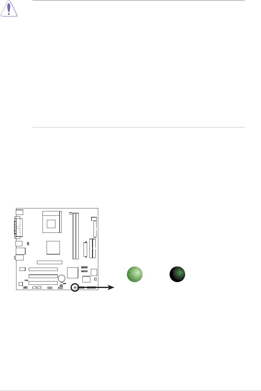
Onboard LED
Onboard LEDOnboard LED
Onboard LEDOnboard LED
The motherboard comes with a standby power LED that lights up to
indicate that the system is ON, in sleep mode, or in soft-off mode. This is a
reminder that you should shut down the system and unplug the power
cable before removing or plugging in any motherboard component. The
illustration below shows the location of the onboard LED.
SB_PWR
A7V400-MX SE
ON
OFF
Standby
Powered
A7V400-MX SE Onboard LED
Power
Off
ASUS A7V400-MX SEASUS A7V400-MX SE
ASUS A7V400-MX SE
ASUS A7V400-MX SEASUS A7V400-MX SE
1-5
1-51-5
1-51-5
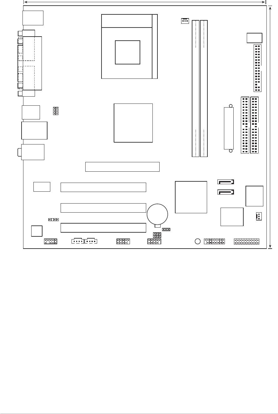
1.5 Motherboard overview
1.5.11.5.1
1.5.1
1.5.11.5.1
Motherboard layout
Motherboard layoutMotherboard layout
Motherboard layoutMotherboard layout
24.5cm (9.6in)
PS/2KBMS
T: Mouse
B: Keyboard
Socket 462
CPU_FAN
COM1
DSW
PARALLEL PORT
FLOPPY
VGA1
USBPWR34
USBPWR12
USB12
VIA
KM400A
DDR DIMM1 (64 bit,184-pin module)
DDR DIMM2 (64 bit,184-pin module)
LAN_USB34
24.5cm (9.6in)
Top:Line In
ATX Power Connector
Center:Line Out
Below:Mic In
Accelerated Graphics Port (AGP1)
PRI_IDE
SEC_IDE
SATA2
VIA
VT6103
PCI1
SATA1
VIA
A7V400-MX SE
ISA
VT8237
2Mbit
BIOS
PCI2
CR2032 3V
Lithium Cell
Super
CMOS Power
SPDIF
I/O
CHA_FAN1
AD1888
PCI3
CLRTC
USBPWR56
USBPWR78
SB_PWR
FP_AUDIO
CDAUX
USB56
USB78
GAME
PANEL
1-61-6
1-6
1-61-6
Chapter 1: Product introduction
Chapter 1: Product introductionChapter 1: Product introduction
Chapter 1: Product introductionChapter 1: Product introduction
1.5.2
1.5.21.5.2
1.5.21.5.2
Placement directionPlacement direction
Placement direction
Placement directionPlacement direction
When installing the motherboard, make sure that you place it into the
chassis in the correct orientation. The edge with external ports goes to the
rear part of the chassis as indicated in the image below.
1.5.31.5.3
1.5.31.5.3
1.5.3
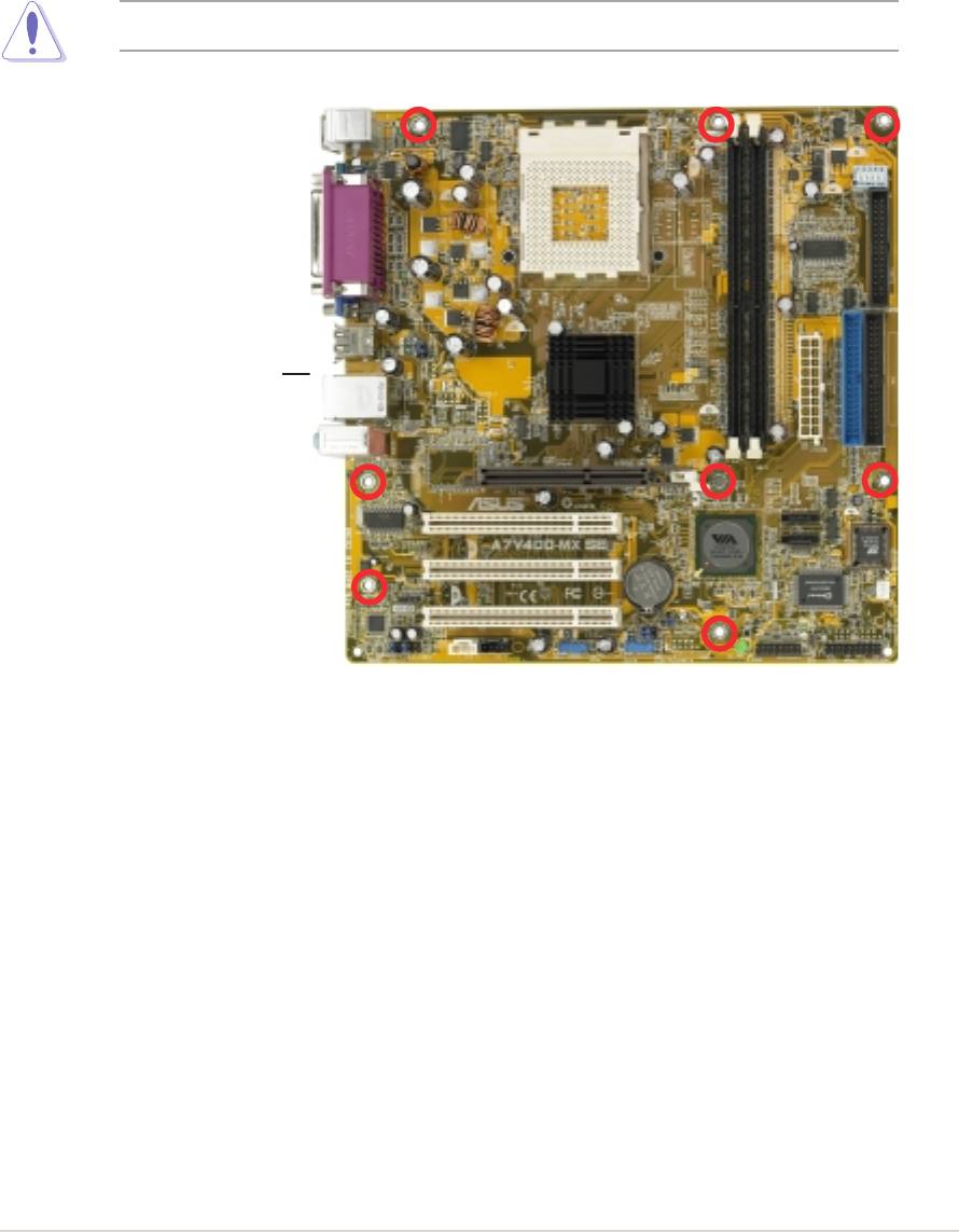
Screw holesScrew holes
Screw holesScrew holes
Screw holes
Place eight (8) screws into the holes indicated by circles to secure the
motherboard to the chassis.
Do not overtighten the screws! Doing so can damage the motherboard.
Place this side towardsPlace this side towards
Place this side towards
Place this side towardsPlace this side towards
the rear of the chassisthe rear of the chassis
the rear of the chassisthe rear of the chassis
the rear of the chassis
ASUS A7V400-MX SEASUS A7V400-MX SE
ASUS A7V400-MX SE
ASUS A7V400-MX SEASUS A7V400-MX SE
1-7
1-71-7
1-71-7
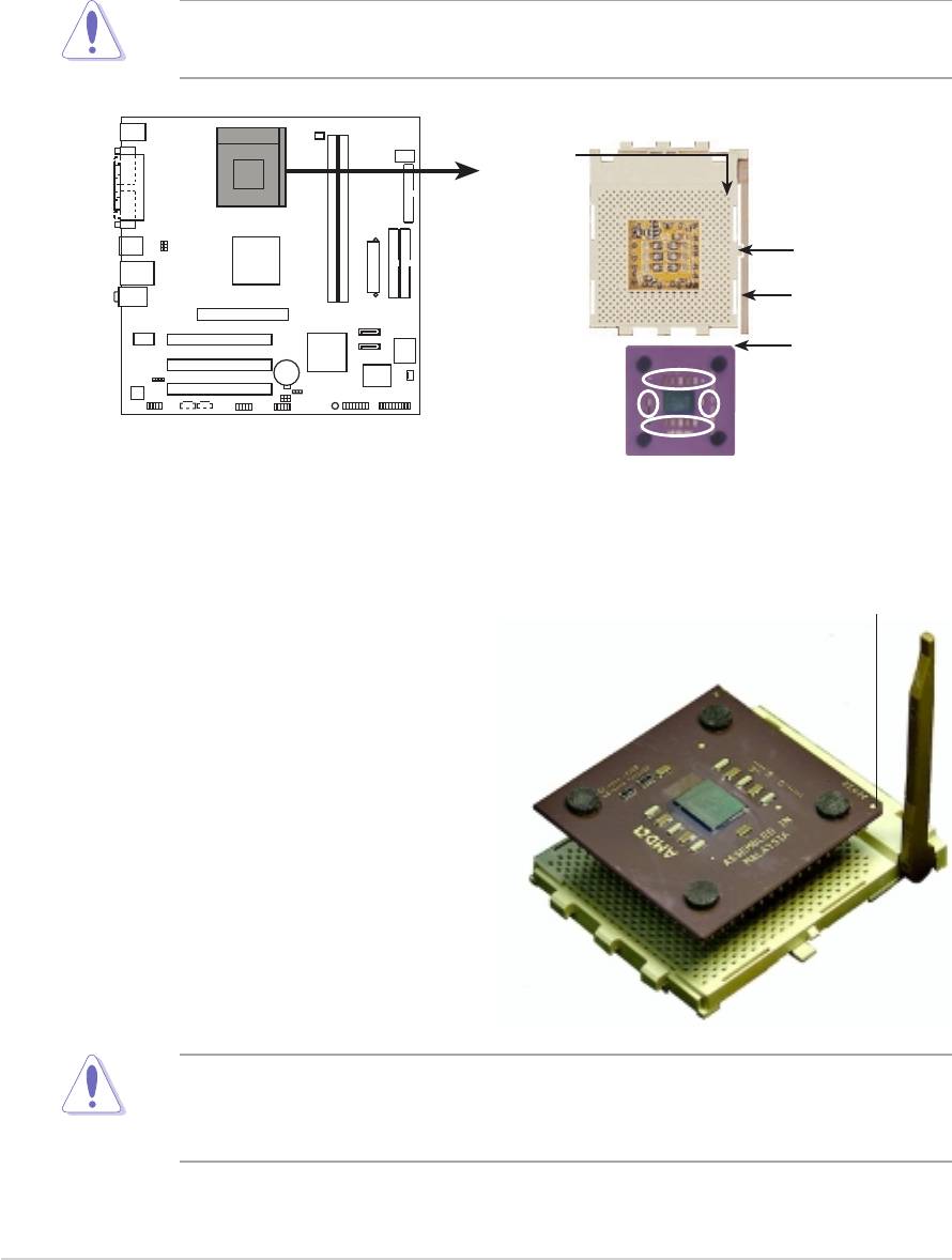
1.6 Central Processing Unit (CPU)
1.6.11.6.1
1.6.11.6.1
1.6.1
Overview
OverviewOverview
OverviewOverview
The motherboard has a Socket A for installation. The Athlon™/Sempron™
CPU has a “marked” corner. This corner is usually indicated with a notch,
and/or a golden square or triangle. Refer to this indicator when orienting
the CPU. A fan and heatsink should be installed on top of the CPU to
prevent overheating.
This motherboard does not support AMD processors with less than
1 GHz core speed.
CPU NOTCH
TO INNER
CORNER
LOCK
LEVER
A7V400-MX SE
CPU NOTCH
AMD™ CPU
A7V400-MX SE Socket 462
1.6.21.6.2
1.6.2
1.6.21.6.2
Installing the CPUInstalling the CPU
Installing the CPU
Installing the CPUInstalling the CPU
Follow these steps to install a CPU:
Golden corner
1. Locate the CPU socket. Open
the socket by pulling the lever
gently sideways away from the
socket, then lift the lever
upwards to a 90 to
100-degree angle.
2. Insert the CPU with the correct
orientation. The notched or
golden corner of the CPU must
be oriented toward the inner
corner of the socket base
nearest to the lever hinge.
The CPU should drop easily into place. Do not force the CPU into the
socket to avoid bending the pins. If the CPU does not fit, check its
alignment and look for bent pins.
1-81-8
1-8
1-81-8
Chapter 1: Product introduction
Chapter 1: Product introductionChapter 1: Product introduction
Chapter 1: Product introductionChapter 1: Product introduction
1.7 System memory
1.7.11.7.1
1.7.11.7.1
1.7.1
Overview
OverviewOverview
OverviewOverview
The motherboard has two Double Data Rate (DDR) DIMM sockets that
support up to 2 GB unbuffered non-ECC DDR400*/333/266/200 DDR
SDRAM DIMMs. Each DIMM socket is double-sided.
A7V400-MX SE
80 Pins 104 Pins
A7V400-MX SE 184-pin DDR DIMM sockets
DIMM1
DIMM2
* You can install a DDR400 DIMM(s) on the slot(s). However, a DDR400
DIMM may only run at speeds of up to 333 MHz (DDR333).
1.7.21.7.2
1.7.21.7.2
1.7.2
Memory configurationsMemory configurations
Memory configurationsMemory configurations
Memory configurations
You may install single or double-sided 64 MB, 128 MB, 256 MB, 512 MB,
and 1 GB DDR DIMMs to the sockets.
For optimum compatibility, it is recommended that you obtain memory
modules from qualified vendors. See the next page for a list of qualified
DDR400 and DDR333 DIMM vendors.
ASUS A7V400-MX SEASUS A7V400-MX SE
ASUS A7V400-MX SE
ASUS A7V400-MX SEASUS A7V400-MX SE
1-9
1-91-9
1-91-9
DDR400 Qualified Vendors ListDDR400 Qualified Vendors List
DDR400 Qualified Vendors List
DDR400 Qualified Vendors ListDDR400 Qualified Vendors List
SizeSize
Size
SizeSize
VendorVendor
Vendor
VendorVendor
ModelModel
ModelModel
Model
CLCL
CLCL
CL
BrandBrand
BrandBrand
Brand
Side(s)Side(s)
Side(s)
Side(s)Side(s)
Component
ComponentComponent
ComponentComponent
256 MB KINGSTON KVR400X64C3A/256 N/A Hynix SS HY5DU56822BT-D43
512 MB KINGSTON KVR400X64C3A/512 N/A Hynix DS HY5DU56822BT-D43
256 MB KINGSTON KVR400X72C3A/256 N/A Mosel SS V58C2256804SAT5(ECC)
512 MB KINGSTON KVR400X72C3A/512 N/A Mosel DS V58C2256804SAT5(ECC)
256 MB KINGSTON KVR400X64C3A/256 N/A Infineon SS HYB25D256800BT-5B
512 MB KINGSTON KVR400X64C3A/512 N/A Infineon DS HYB25D256809BT-5B
256 MB KINGSTON KVR400X64C3A/256 N/A KINGSTON SS D3208DL2T-5
512 MB KINGSTON KHX3200A/512 N/A N/A DS N/A
1024 MB KINGSTON KVR400X64C3A/1G 3 N/A DS HYB25D512800BE-5B
1024 MB KINGSTON KHX3200ULK2/1G 2 N/A DS N/A
256 MB SAMSUNG M381L3223ETM-CCC 3ECC SAMSUNG SS K4H560838E-TCCC(ECC)
512 MB SAMSUNG M381L6423ETM-CCC N/A SAMSUNG DS K4H560838E-TCCC(ECC)
256 MB SAMSUNG M368L3223ETM-CCC N/A SAMSUNG SS K4H560838E-TCCC
256 MB SAMSUNG M368L3223FTN-CCC 3 SAMSUNG SS K4H560838F-TCCC
512 MB SAMSUNG M368L6423FTN-CCC 3 SAMSUNG DS K4H560838F-TCCC
512 MB SAMSUNG M368L6523BTM-CCC 3 SAMSUNG SS K4H510838B-TCCC
256 MB MICRON MT8VDDT3264AG-40BCB N/A MICRON SS MT46V32M8TG-5BC
512 MB MICRON MT16VDDT6464AG-40BCB N/A MICRON DS MT46V32M8TG-5BC
256 MB Infineon HYS64D32300HU-5-C 3 Infineon SS HYB25D256800CE-5C
512 MB Infineon HYS64D64320HU-5-C N/A Infineon DS HYB25D256800CE-5C
256 MB CORSAIR CMX256A-3200C2PT 2 Winbond SS W942508BH-5
512 MB CORSAIR CMX512-3200C2 2 Winbond DS N/A
512 MB CORSAIR VS512MB400 2.5 VALUE seLecT DS VS32M8-5
1024 MB CORSAIR TWINX2048-3200C2 3 N/A DS N/A
256 MB Hynix HYMD232645D8J-D43 3 Hynix SS HY5DU56822DT-D43
512 MB Hynix HYMD264646D8J-D43 3 Hynix DS HY5DU56822DT-D43
256 MB TwinMOS M2G9I08AIATT9F081AADT 2.5 TwinMOS SS TMD7608F8E50D
512 MB TwinMOS M2G9J16AJATT9F081AADT 2.5 TwinMOS DS TMD7608F8E50D
256 MB TwinMOS M2G9I08A8ATT9F081AADT 2.5 TwinMOS SS TMD7608F8E50D
512 MB TwinMOS M2G9J16A8ATT9F081AADT 2.5 TwinMOS DS TMD7608F8E50D
256 MB Transcend TS32MLD64V4F3 3 SAMSUNG SS K4H560838F-TCCC
512 MB Transcend TS64MLD64V4F3 3 SAMSUNG DS K4H560838F-TCCC
1024 MB Transcend TS128MLD64V4J 3 SAMSUNG DS K4H510838B-TCCC
256 MB Apacer 77.10636.33G 3 Infineon SS HYB25D256800CE-5C
512 MB Apacer 77.10736.33G 3 Infineon DS HYB25D256800CE-5C
256 MB Apacer 77.10639.60G 2.5 ProMOS SS V58C2256804SCT5B
512 MB Apacer 77.10739.60G 2.5 ProMOS DS V58C2256804SCT5B
256 MB A DATA MDOSS6F3G31Y0K1E0Z 3 SAMSUNG SS K4H560838E-TCCC
512 MB A DATA MDOSS6F3H41Y0N1E0Z 3 SAMSUNG DS K4H560838F-TCCC
256 MB A DATA MDOHY6F3G31Y0N1E0Z 3 Hynix SS HY5DU56822CT-D43
512 MB A DATA MDOHY6F3H41Y0N1E0Z 3 Hynix DS HY5DU56822CT-D43
256 MB A DATA MDOAD5F3G31Y0D1E02 2.5 N/A SS ADD8608A8A-5B
512 MB A DATA MDOAD5F3H41Y0D1E02 2.5 N/A DS ADD8608A8A-5B
256 MB Winbond W9425GCDB-5 3 Winbond SS W942508CH-5
512 MB Winbond W9451GCDB-5 N/A Winbond DS W942508CH-5
256 MB PSC AL5D8B53T-5B1K 2.5 PSC SS A2S56D30BTP
512 MB PSC AL6D8B53T-5B1K 2.5 PSC DS A2S56D30BTP
256 MB KINGMAX MPXB62D-38KT3R N/A N/A SS KDL388P4LA-50
512 MB KINGMAX MPXC22D-38KT3R N/A N/A DS KDL388P4LA-50
512 MB SAMSUNG M378T6553BG0-CD5 N/A N/A SS K4T51083QB-GCD5
1-101-10
1-10
1-101-10
Chapter 1: Product introduction
Chapter 1: Product introductionChapter 1: Product introduction
Chapter 1: Product introductionChapter 1: Product introduction
DDR400 Qualified Vendors List (continuation)
DDR400 Qualified Vendors List (continuation)DDR400 Qualified Vendors List (continuation)
DDR400 Qualified Vendors List (continuation)DDR400 Qualified Vendors List (continuation)
SizeSize
Size
SizeSize
Vendor
VendorVendor
VendorVendor
ModelModel
Model
ModelModel
CL
CLCL
CLCL
BrandBrand
BrandBrand
Brand
Side(s)Side(s)
Side(s)
Side(s)Side(s)
ComponentComponent
Component
ComponentComponent
256 MB NANYA NT256D64S88C0G-5T 3 N/A SS NT5DS32M8CT-5T
512 MB NANYA NT512D64S8HC0G-5T 3 N/A DS NT5DS32M8CT-5T
256 MB BRAIN POWERB6U808-256M-SAM-400 N/A SAMSUNG SS K4H560838D-TCC4
512 MB BRAIN POWERB6U808-512M-SAM-400 N/A SAMSUNG DS K4H560838D-TCC4
256 MB CENTURY DXV6S8SSCCE3K27E N/A SAMSUNG SS K4H560838E-TCCC
512 MB CENTURY DXV2S8SSCCE3K27E N/A SAMSUNG DS K4H560838E-TCCC
256 MB CENTURY DXV6S8EL5BM3T27C N/A N/A SS DD2508AMTA
512 MB CENTURY DXV2S8EL5BM3T27C N/A N/A DS DD2508AMTA
256 MB elixir M2U25664DS88C3G-5T 3 elixir SS N2DS25680CT-5T
512 MB elixir M2U51264DS8HC1G-5T 3 elixir DS N2DS25680CT-5T
256 MB Kreton N/A N/A VT SS VT3225804T-5
512 MB Kreton N/A N/A VT DS VT3225804T-5
256 MB Veritech VT400FMV/2561103 3 VT SS VT56DD32M8PC-5
512 MB Veritech VT400FMV/5121003 3 VT DS VT56DD32M8PC-5
256 MB Pmi MD44256VIT3208GMHA01 2.5 MOSEL SS V58C2256804SAT5B
512 MB Pmi MD44512VIT3208GATA03 2.5 MOSEL DS V58C2256804SAT5B
256 MB ProMOS V826632K24SCTG-D0 2.5 N/A SS V58C2256804SCT5B
512 MB ProMOS V826664K24SCTG-D0 2.5 N/A DS V58C2256804SCT5B
256 MB Deutron AL5D8C53T-5B1T 2.5 PSC SS A2S56D30CTP
512 MB Deutron AL6D8C53T-5B1T 2.5 PSC DS A2S56D30CTP
256 MB GEIL GL5123200DC N/A N/A SS GL3LC32G88TG-35
512 MB GEIL GL1GB3200DC N/A N/A DS GL3LC32G88TG-35
256 MB GEIL GLX2563200UP N/A N/A SS GL3LC32G88TG-5A
256 MB GEIL GD3200-512DC N/A N/A SS WLCSP Package
256 MB crucial BL3264Z402.8TG 2 Ballistix SS N/A
512 MB crucial BL6464Z402.16TG 2 Ballistix DS N/A
256 MB Novax 96M425653CE-40TB6 2.5 CEON SS C2S56D30TP-5
512 MB Novax 96M451253CE-40TB6 2.5 CEON DS C2S56D30TP-5
Side(s)Side(s)
Side(s)Side(s)
Side(s):
SSSS
SSSS
S S - Single-sided
DSDS
DSDS
D S - Double-sided
CLCL
CLCL
C L - CAS Latency
Visit the ASUS website for the latest DDR400 Qualified Vendors List.
ASUS A7V400-MX SEASUS A7V400-MX SE
ASUS A7V400-MX SE
ASUS A7V400-MX SEASUS A7V400-MX SE
1-11
1-111-11
1-111-11
DDR333 Qualified Vendors ListDDR333 Qualified Vendors List
DDR333 Qualified Vendors ListDDR333 Qualified Vendors List
DDR333 Qualified Vendors List
Size
SizeSize
SizeSize
VendorVendor
Vendor
VendorVendor
ModelModel
ModelModel
Model
CLCL
CLCL
CL
BrandBrand
BrandBrand
Brand
Side(s)Side(s)
Side(s)
Side(s)Side(s)
Component
ComponentComponent
ComponentComponent
256 MB NANYA NT256D64S88C0G-5T 3 N/A SS NT5DS32M8CT-5T
256 MB SAMSUNG M368L3223ETN-CB3 N/A SAMSUNG SS K4H560838E-TCB3
512 MB SAMSUNG M368L6423ETN-CB3 2.5 SAMSUNG DS K4H560838E-TCB3
256 MB SAMSUNG M381L3223ETM-CB3 2.5ECC SAMSUNG SS K4H560838E-TCB3(ECC)
512 MB SAMSUNG M381L6423ETM-CB3 2.5ECC SAMSUNG DS K4H560838E-TCB3(ECC)
256 MB SAMSUNG M368L3223FTN-CB3 2.5 SAMSUNG SS K4H560838F-TCB3
256 MB MICRON MT8VDDT3264AG-335CA 2.5 MICRON SS MT46V32M8TG-6TC
512 MB MICRON MT16VDDT6464AG-335CA 2.5 MICRON DS MT46V32M8TG-6TC
256 MB CORSAIR VS256MB333 2.5 VALUE seLecT SS VS32M8-6
512 MB CORSAIR VS512MB333 N/A VALUE seLecT DS VS32M8-6
256 MB KINGSTON KVR333X64C25/256 2.5 KINGSTON SS D3208DH1T-6
512 MB KINGSTON KVR333X64C25/512 2.5 KINGSTON DS D3208DH1T-6
256 MB PQI MD3456UPS N/A PQI SS PQ3D328S6-0246
512 MB TwinMos M2G5J16AJATT5F081AA4T 2.5 TwinMos DS TMD7608F8E60D
512 MB MOSEL MPMC225-383 N/A MOSEL DS V58C2256804SAT6
256 MB Transcend TS32MLD64V3F5 N/A SAMSUNG SS K4H560838F-TCCC
256 MB elixir M2U25664DS88C3G-6K 2.5 elixir SS N2DS25680CT-6K
512 MB elixir M2U51264DS8HC1G-6K 2.5 elixir DS N2DS25680CT-6K
256 MB Veritech VT333FMV/2561103 2.5 VT SS VT56DD32M8PC-6
512 MB Veritech VT333FMV/5121103 2.5 VT DS VT56DD32M8PC-6
256 MB NANYA NT256D64S88C0G-6K 2.5 N/A SS NT5DS32M8CT-6K
512 MB NANYA NT512D64S8HC0G-6K 2.5 N/ A DS NT5DS32M8CT-6K
1024 MB NANYA NT1GD64S8HA0F-6K 2.5-3-3 HANYA DS NT5DS64M8AF-6K
Side(s)Side(s)
Side(s):
Side(s)Side(s)
SSSS
S S - Single-sided
SSSS
D S - Double-sided
DSDS
DSDS
CLCL
CLCL
C L - CAS Latency
Visit the ASUS website for the latest DDR333 Qualified Vendors List.
1-121-12
1-12
1-121-12
Chapter 1: Product introduction
Chapter 1: Product introductionChapter 1: Product introduction
Chapter 1: Product introductionChapter 1: Product introduction
1.7.31.7.3
1.7.31.7.3
1.7.3
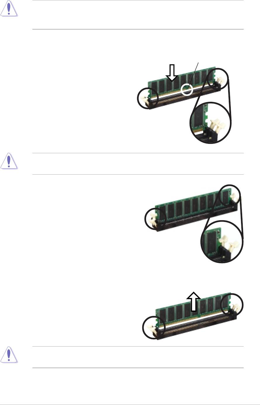
Installing a DIMMInstalling a DIMM
Installing a DIMM
Installing a DIMMInstalling a DIMM
Make sure to unplug the power supply before adding or removing DIMMs
or other system components. Failure to do so may cause severe damage
to both the motherboard and the components.
Follow these steps to install a DIMM.
1. Locate the DIMM sockets in the
DDR DIMM notch
motherboard.
2. Unlock a DIMM socket by
pressing the retaining clips
outward.
3. Align a DIMM on the socket such
that the notch on the DIMM
Unlocked Retaining
matches the break on the
Clip
socket.
A DDR DIMM is keyed with a notch so that it fits in only one direction.
DO NOT force a DIMM into a socket to avoid damaging the DIMM.
4. Firmly insert the DIMM into the
socket until the retaining clips
snap back in place and the DIMM
is properly seated.
Locked Retaining Clip
1.7.4
1.7.41.7.4
1.7.41.7.4
Removing a DIMM
Removing a DIMMRemoving a DIMM
Removing a DIMMRemoving a DIMM
Follow these steps to remove a DIMM.
1. Simultaneously press the
retaining clips outward to unlock
the DIMM.
Support the DIMM lightly with your fingers when pressing the retaining
clips. The DIMM might get damaged when it flips out with extra force.
2. Remove the DIMM from the socket.
ASUS A7V400-MX SEASUS A7V400-MX SE
ASUS A7V400-MX SE
ASUS A7V400-MX SEASUS A7V400-MX SE
1-13
1-131-13
1-131-13

1.8 Expansion slots
In the future, you may need to install expansion cards. The following
sub-sections describe the slots and the expansion cards that they support.
Make sure to unplug the power cord before adding or removing
expansion cards. Failure to do so may cause you physical injury and
damage motherboard components.
1.8.11.8.1
1.8.11.8.1
1.8.1
Installing an expansion cardInstalling an expansion card
Installing an expansion cardInstalling an expansion card
Installing an expansion card
To install an expansion card:
1. Before installing the expansion card, read the documentation that
came with it and make the necessary hardware settings for the card.
2. Remove the system unit cover (if your motherboard is already
installed in a chassis).
3. Remove the bracket opposite the slot that you intend to use. Keep
the screw for later use.
4. Align the card connector with the slot and press firmly until the card is
completely seated on the slot.
5. Secure the card to the chassis with the screw you removed earlier.
6. Replace the system cover.
1.8.21.8.2
1.8.2
1.8.21.8.2
Configuring an expansion card
Configuring an expansion cardConfiguring an expansion card
Configuring an expansion cardConfiguring an expansion card
After installing the expansion card, configure the it by adjusting the
software settings.
1. Turn on the system and change the necessary BIOS settings, if any.
See Chapter 2 for information on BIOS setup.
2. Assign an IRQ to the card. Refer to the tables on the next page.
3. Install the software drivers for the expansion card.
1-14
1-141-14
1-141-14
Chapter 1: Product introductionChapter 1: Product introduction
Chapter 1: Product introductionChapter 1: Product introduction
Chapter 1: Product introduction
Standard interrupt assignmentsStandard interrupt assignments
Standard interrupt assignmentsStandard interrupt assignments
Standard interrupt assignments
IRQ
IRQIRQ
IRQIRQ
PriorityPriority
PriorityPriority
Priority
Standard FunctionStandard Function
Standard Function
Standard FunctionStandard Function
0 1 System Timer
1 2 Keyboard Controller
2 - Re-direct to IRQ#9
4 12 Communications Port (COM1)*
5 13 IRQ holder for PCI steering*
6 14 Floppy Disk Controller
7 15 Printer Port (LPT1)*
8 3 System CMOS/Real Time Clock
9 4 IRQ holder for PCI steering*
10 5 IRQ holder for PCI steering*
11 6 IRQ holder for PCI steering*
12 7 PS/2 Compatible Mouse Port*
13 8 Numeric Data Processor
14 9 Primary IDE Channel
15 10 Secondary IDE Channel
* These IRQs are usually available for ISA or PCI devices.* These IRQs are usually available for ISA or PCI devices.
* These IRQs are usually available for ISA or PCI devices.* These IRQs are usually available for ISA or PCI devices.
* These IRQs are usually available for ISA or PCI devices.
IRQ assignments for this motherboardIRQ assignments for this motherboard
IRQ assignments for this motherboardIRQ assignments for this motherboard
IRQ assignments for this motherboard
A
AA
AA
BB
B
BB
C
CC
CC
D
DD
DD
PCI slot 1 ——used —
PCI slot 2 ———used
PCI slot 3 shared ———
AGP slot — shared ——
When using PCI cards on shared slots, ensure that the drivers support
“Share IRQ” or that the cards do not need IRQ assignments; otherwise,
conflicts will arise between the two PCI groups, making the system
unstable and the card inoperable.
ASUS A7V400-MX SEASUS A7V400-MX SE
ASUS A7V400-MX SE
ASUS A7V400-MX SEASUS A7V400-MX SE
1-15
1-151-15
1-151-15
1.8.31.8.3
1.8.3
1.8.31.8.3
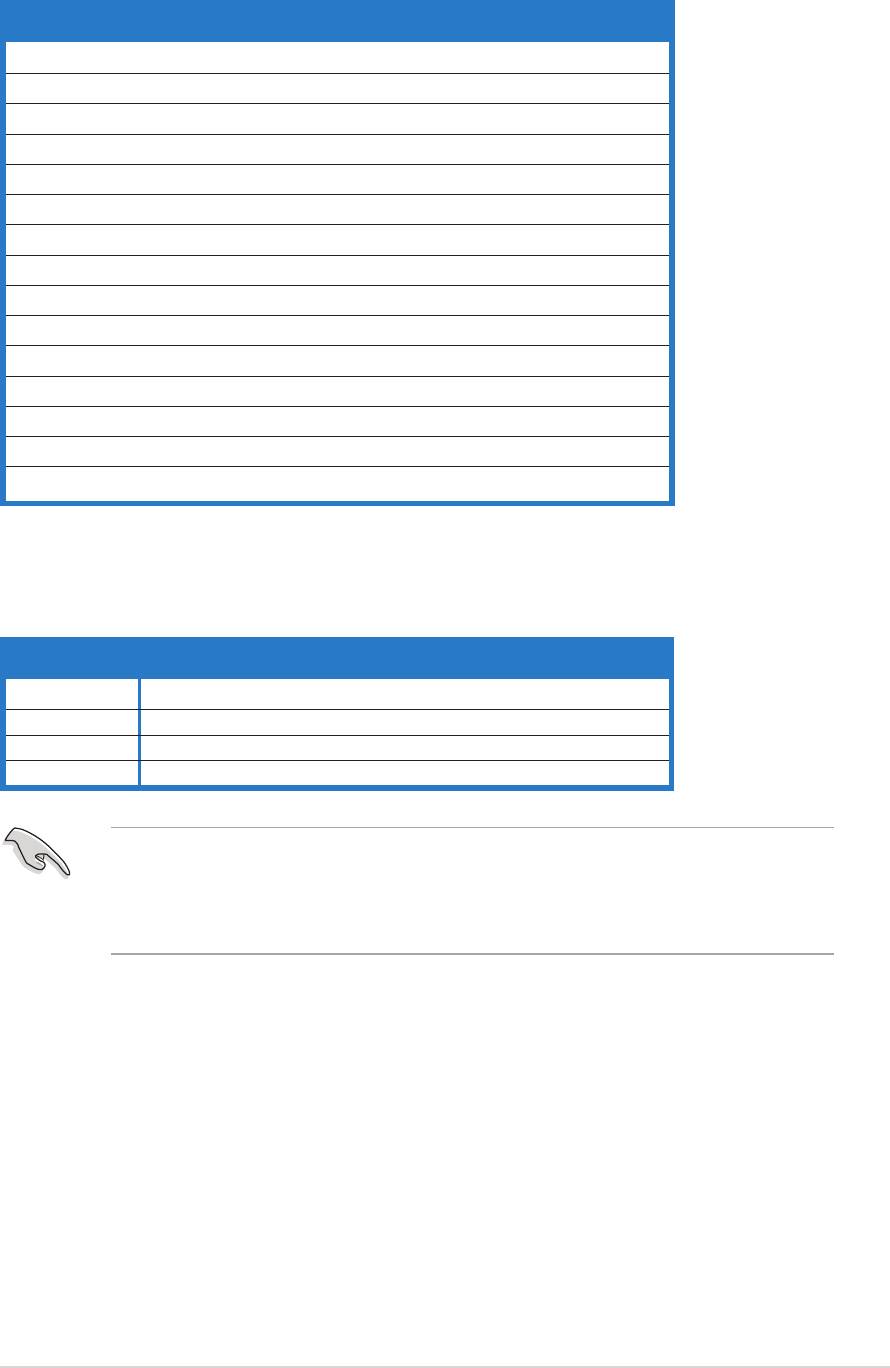
AGP slotAGP slot
AGP slot
AGP slotAGP slot
The motherboard has an Accelerated Graphics Port (AGP) slot that
supports +1.5 V 8X/4X AGP graphics card. Note the notches on the card
golden fingers to ensure that they fit into the AGP slot.
A7V400-MX SE
Keyed for 1.5v
A7V400-MX SE Accelerated Graphics Port (AGP)
1.8.4
1.8.41.8.4
1.8.41.8.4
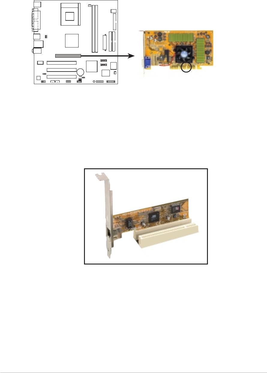
PCI slots
PCI slotsPCI slots
PCI slotsPCI slots
The PCI slots support cards such as a LAN card, SCSI card, USB card, and
other cards that comply with PCI specifications. The figure shows a LAN
card installed on a PCI slot.
1-161-16
1-16
1-161-16
Chapter 1: Product introduction
Chapter 1: Product introductionChapter 1: Product introduction
Chapter 1: Product introductionChapter 1: Product introduction
1.9 Switch and jumpers
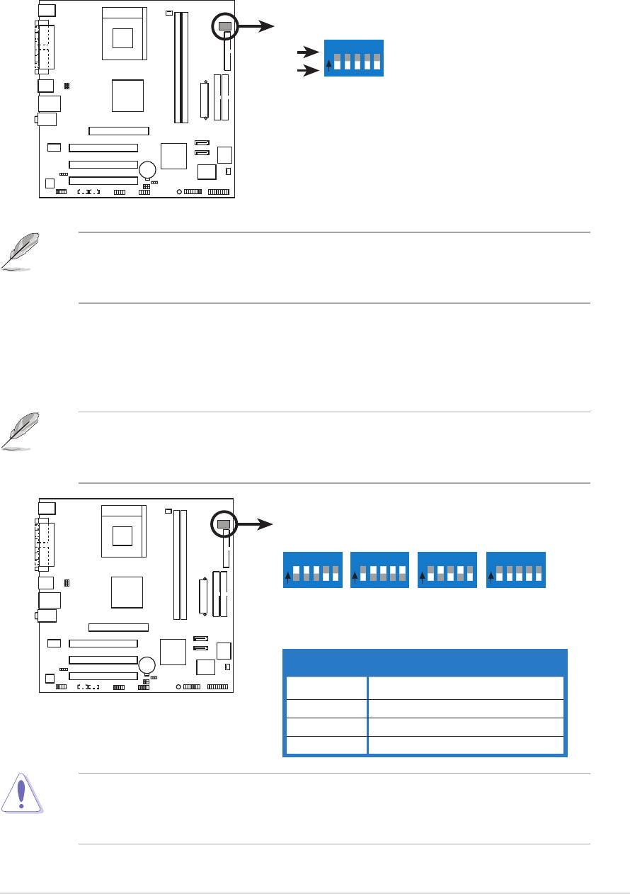
1.1.
1.1.
1.
CPU external frequency selection (DSW Switches 1-5)CPU external frequency selection (DSW Switches 1-5)
CPU external frequency selection (DSW Switches 1-5)CPU external frequency selection (DSW Switches 1-5)
CPU external frequency selection (DSW Switches 1-5)
The motherboard frequency is adjusted through the DIP switches.
The white block represents the switch position. The illustration below
shows the ON and OFF positions of the switches.
(Default)
O
12345
ON
N
OFF
100MHz
66.67MHz
33.33MHz
A7V400-MX SE
A7V400-MX SE DIP switches
The option to set the CPU core bus frequency multiple is available only
on unlocked CPUs. If you are using a locked CPU, setting the switches
does not produce any effect.
The DSW switch tells the clock generator what frequency to send the
CPU. This allows the selection of the CPU’s external frequency (or bus
clock). The bus clock multiplied by the frequency multiple equals the
CPU’s internal frequency (the advertised CPU speed).
The default CPU external frequency is 100 MHz. If your CPU supports
200/166/133 MHz external frequency, adjust the DSW settings before
installing the motherboard to the chassis.
DSW
(Default)
O
12345
O
12345
O
12345
O
12345
N
N
N
N
CPU
200MHz
166.67MHz
133.33MHz
100MHz
AGP
66.67MHz
66.67MHz
66.67MHz
66.67MHz
PCI
33.33MHz
33.33MHz
33.33MHz
33.33MHz
A7V400-MX SE
FSBFSB
FSB
FSBFSB
CPU External FrequencyCPU External Frequency
CPU External FrequencyCPU External Frequency
CPU External Frequency
400 200 MHz
A7V400-MX SE CPU
333 166 MHz
external frequency selection
266 133 MHz
200 100 MHz
Set the CPU frequency only to the recommended settings. Frequencies
other than the recommended CPU bus frequencies are not guaranteed to
be stable.
ASUS A7V400-MX SEASUS A7V400-MX SE
ASUS A7V400-MX SE
ASUS A7V400-MX SEASUS A7V400-MX SE
1-17
1-171-17
1-171-17
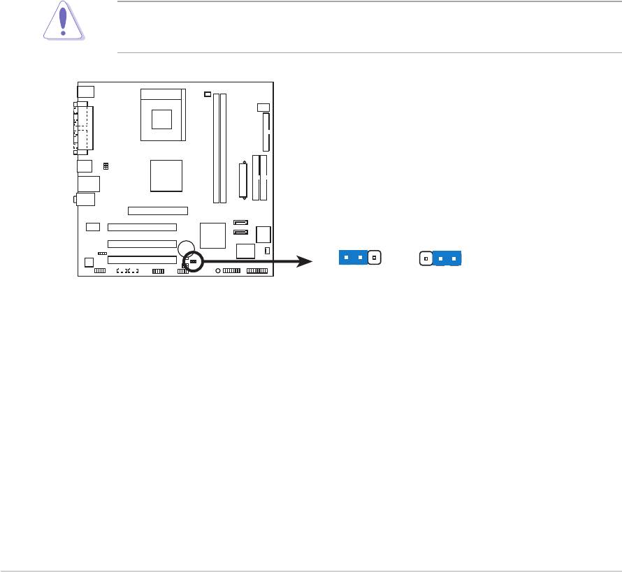
2.2.
2.2.
2.
Clear RTC RAM (CLRTC)
Clear RTC RAM (CLRTC)Clear RTC RAM (CLRTC)
Clear RTC RAM (CLRTC)Clear RTC RAM (CLRTC)
This jumper allows you to clear the Real Time Clock (RTC) RAM in
CMOS. You can clear the CMOS memory of date, time, and system
setup parameters by erasing the CMOS RTC RAM data. The onboard
button cell battery powers the RAM data in CMOS, which include
system setup information such as system passwords.
To erase the RTC RAM:
1. Turn OFF the computer and unplug the power cord.
2. Remove the onboard battery.
3. Move the jumper cap from pins 2-3 (default) to pins 1-2. Keep the
cap on pins 1-2 for about 5~10 seconds, then move the cap back to
pins 2-3.
4. Reinstall the battery.
5. Plug the power cord and turn ON the computer.
6. Hold down the <Del> key during the boot process and enter BIOS
setup to re-enter data.
Except when clearing the RTC RAM, never remove the cap on CLRTC
jumper default position. Removing the cap will cause system boot failure!
CLRTC
A7V400-MX SE
12 23
NormalClear CMOS
A7V400-MX SE Clear RTC RAM
(Default)
1-181-18
1-18
1-181-18
Chapter 1: Product introduction
Chapter 1: Product introductionChapter 1: Product introduction
Chapter 1: Product introductionChapter 1: Product introduction
3.3.
3.3.
3.
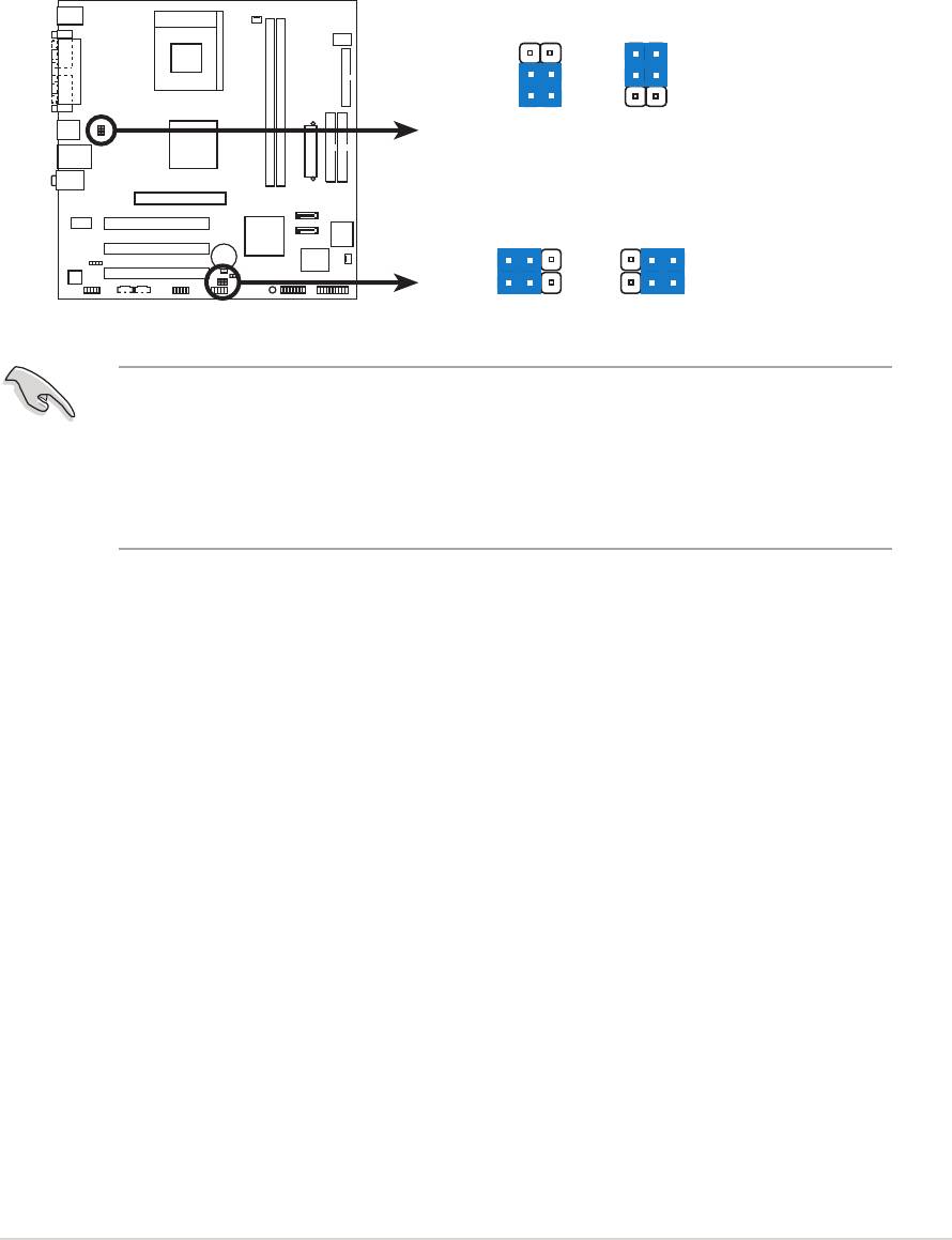
USB device wake-up (3-pin USBPWR12, USBPWR34,USB device wake-up (3-pin USBPWR12, USBPWR34,
USB device wake-up (3-pin USBPWR12, USBPWR34,USB device wake-up (3-pin USBPWR12, USBPWR34,
USB device wake-up (3-pin USBPWR12, USBPWR34,
USBPWR56, USBPWR78)USBPWR56, USBPWR78)
USBPWR56, USBPWR78)USBPWR56, USBPWR78)
USBPWR56, USBPWR78)
Set these jumpers to +5V to wake up the computer from S1 sleep
mode (CPU stopped, DRAM refreshed, system running in low power
mode) using the connected USB devices. Set to +5VSB to wake up
from S3 and S4 sleep modes (no power to CPU, DRAM in slow refresh,
power supply in reduced power mode).
USBPWR12
USBPWR34
3
2
2
1
+5V
+5VSB
(Default)
USBPWR56
USBPWR78
A7V400-MX SE
2321
+5V
+5VSB
A7V400-MX SE USB device wake up
(Default)
• The USB device wake-up feature requires a power supply that can
provide 500mA on the +5VSB lead for each USB port; otherwise,
the system will not power up.
• The total current consumed must NOT exceed the power supply
capability (+5VSB) whether under normal condition or in sleep mode.
ASUS A7V400-MX SEASUS A7V400-MX SE
ASUS A7V400-MX SE
ASUS A7V400-MX SEASUS A7V400-MX SE
1-19
1-191-19
1-191-19
1.10 Connectors
1.10.1
1.10.11.10.1
1.10.11.10.1
Rear panel connectors
Rear panel connectorsRear panel connectors
Rear panel connectorsRear panel connectors
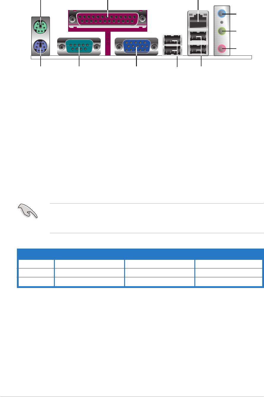
1
2 3
4
5
6
11
910
8
7
1.1.
1.1.
1.
PS/2 mouse port (green).PS/2 mouse port (green).
PS/2 mouse port (green). This port is for a PS/2 mouse.
PS/2 mouse port (green).PS/2 mouse port (green).
2.2.
2.2.
2.
Parallel port.Parallel port.
Parallel port.Parallel port.
Parallel port. This 25-pin port connects a parallel printer, a scanner,
or other devices.
3.
3.3.
3.3.
LAN (RJ-45) port.LAN (RJ-45) port.
LAN (RJ-45) port.LAN (RJ-45) port.
LAN (RJ-45) port. This port allows 10/100 Mbps connection to a
Local Area Network (LAN) through a network hub.
4.4.
4.
4.4.
Line In port (light blue).Line In port (light blue).
Line In port (light blue).Line In port (light blue).
Line In port (light blue). This port connects a tape, CD, DVD
player or other audio sources. In 6-channel mode, the function of this
port becomes Bass/Center.
5.5.
5.5.
5.
Line Out port (lime).Line Out port (lime).
Line Out port (lime).Line Out port (lime).
Line Out port (lime). This port connects a headphone or a
speaker. In 4/6-channel mode, the function of this port becomes
Front Speaker Out.
6.6.
6.6.
6.
Microphone port (pink). Microphone port (pink).
Microphone port (pink). Microphone port (pink).
Microphone port (pink). This port connects a microphone. In
4/6-channel mode, the function of this port becomes Rear Speaker Out.
The functions of the Line Out, Line In, and Microphone ports change
when you select the 4 or 6-channel audio configuration as shown in the
following table.
Audio 2, 4, or 6-channel configuration
Audio 2, 4, or 6-channel configurationAudio 2, 4, or 6-channel configuration
Audio 2, 4, or 6-channel configurationAudio 2, 4, or 6-channel configuration
PortPort
Port
PortPort
Headset/Headset/
Headset/Headset/
Headset/
2-channel2-channel
2-channel2-channel
2-channel
4-channel
4-channel4-channel
4-channel4-channel
6-channel
6-channel6-channel
6-channel6-channel
Light Blue Line In Line In Bass/Center
Lime Line Out Front Speaker Out Front Speaker Out
Pink Mic In Rear Speaker Out Rear Speaker Out
7.7.
7.7.
7.
USB 2.0 ports 3 and 4.USB 2.0 ports 3 and 4.
USB 2.0 ports 3 and 4.USB 2.0 ports 3 and 4.
USB 2.0 ports 3 and 4. These two 4-pin Universal Serial Bus
(USB) ports are available for connecting USB 2.0 devices.
8.8.
8.8.
8.
USB 2.0 ports 1 and 2.USB 2.0 ports 1 and 2.
USB 2.0 ports 1 and 2.USB 2.0 ports 1 and 2.
USB 2.0 ports 1 and 2. These two 4-pin Universal Serial Bus
(USB) ports are available for connecting USB 2.0 devices.
9.
9.9.
9.9.
Video Graphics Adapter port. Video Graphics Adapter port.
Video Graphics Adapter port. Video Graphics Adapter port.
Video Graphics Adapter port. This 15-pin port is for a VGA
monitor or other VGA-compatible devices.
10.10.
10.10.
10.
Serial port. This 9-pin COM1 port is for pointing devices or other
Serial portSerial port
Serial portSerial port
serial devices.
11.11.
11.11.
11.
PS/2 keyboard port (purple). This port is for a PS/2 keyboard.
PS/2 keyboard port (purple).PS/2 keyboard port (purple).
PS/2 keyboard port (purple).PS/2 keyboard port (purple).
1-20
1-201-20
1-201-20
Chapter 1: Product introductionChapter 1: Product introduction
Chapter 1: Product introductionChapter 1: Product introduction
Chapter 1: Product introduction
1.10.21.10.2
1.10.21.10.2
1.10.2
Internal connectors
Internal connectorsInternal connectors
Internal connectorsInternal connectors
1.
1.1.
1.1.
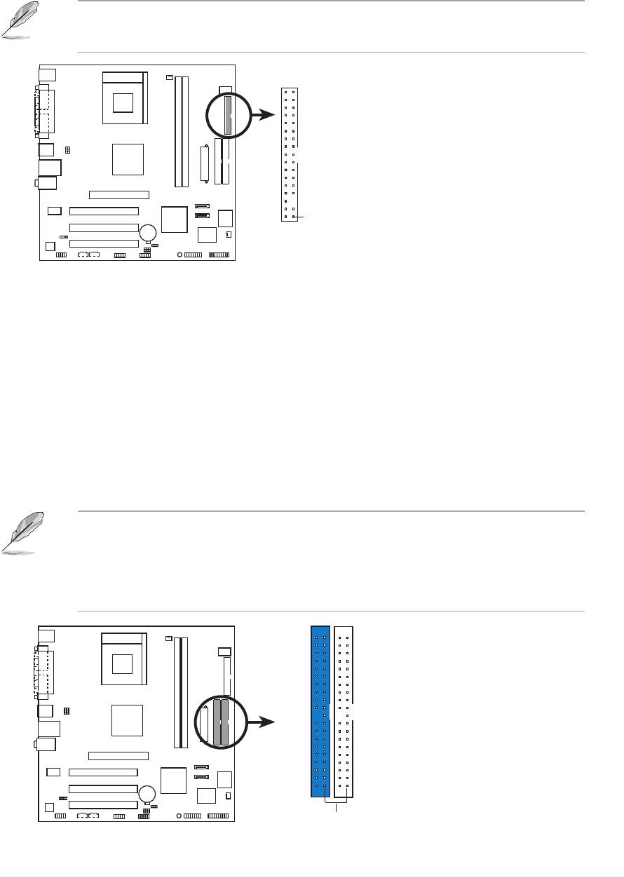
Floppy disk drive connector (34-1 pin FLOPPY)
Floppy disk drive connector (34-1 pin FLOPPY)Floppy disk drive connector (34-1 pin FLOPPY)
Floppy disk drive connector (34-1 pin FLOPPY)Floppy disk drive connector (34-1 pin FLOPPY)
This connector is for the provided floppy disk drive (FDD) signal cable.
Insert one end of the cable to this connector, then connect the other
end to the signal connector at the back of the floppy disk drive.
Pin 5 on the connector is removed to prevent incorrect cable connection
when using a FDD cable with a covered Pin 5.
FLOPPY
NOTE: Orient the red markings on
the floppy ribbon cable to PIN 1.
A7V400-MX SE
PIN 1
A7V400-MX SE Floppy disk drive connector
2.
2.2.
2.2.
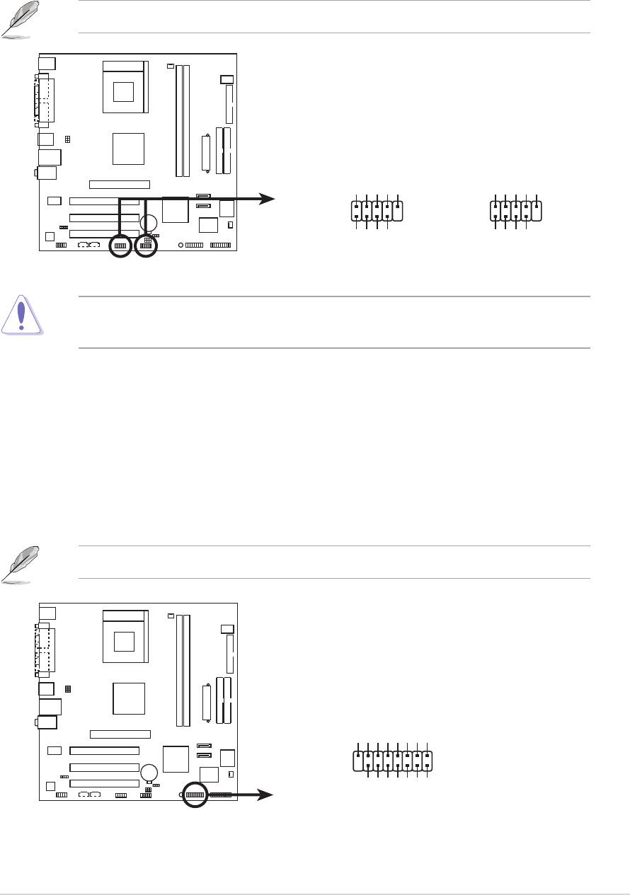
IDE connectors (40-1 pin PRI_IDE, SEC_IDE)
IDE connectors (40-1 pin PRI_IDE, SEC_IDE)IDE connectors (40-1 pin PRI_IDE, SEC_IDE)
IDE connectors (40-1 pin PRI_IDE, SEC_IDE)IDE connectors (40-1 pin PRI_IDE, SEC_IDE)
This connector is for an Ultra DMA 133 signal cable. The Ultra
DMA 133 signal cable has three connectors: a blue connector for the
IDE connector on the motherboard, a black connector for an Ultra DMA
133/100/66 IDE slave device (optical drive/hard disk drive), and a gray
connector for an Ultra DMA 133/100/66 IDE master device (hard disk
drive). If you install two hard disk drives, you must configure the
second drive as a slave device by setting its jumper accordingly.
Refer to the hard disk documentation for the jumper settings.
• Pin 20 on the IDE connector is removed to match the covered hole
on the Ultra DMA cable connector. This prevents incorrect insertion
when you connect the IDE cable.
• Use the 80-conductor IDE cable for Ultra DMA 133/100/66 IDE devices.
NOTE: Orient the red markings
(usually zigzag) on the IDE
ribbon cable to PIN 1.
A7V400-MX SE
PRI_IDE
SEC_IDE
PIN 1
A7V400-MX SE IDE connectors
ASUS A7V400-MX SEASUS A7V400-MX SE
ASUS A7V400-MX SE
ASUS A7V400-MX SEASUS A7V400-MX SE
1-21
1-211-21
1-211-21
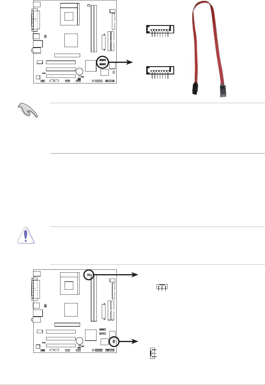
3.3.
3.
3.3.
Serial ATA connectors (7-pin SATA1, SATA2)
Serial ATA connectors (7-pin SATA1, SATA2)Serial ATA connectors (7-pin SATA1, SATA2)
Serial ATA connectors (7-pin SATA1, SATA2)Serial ATA connectors (7-pin SATA1, SATA2)
These connectors are for the Serial ATA signal cables for Serial ATA
hard disk drives.
SATA2
GND
GND
GND
RSATA_TXP2
RSATA_TXN2
RSATA_RXP2
RSATA_RXN2
SATA1
A7V400-MX SE
GND
GND
GND
A7V400-MX SE SATA connector
RSATA_TXP1
RSATA_TXN1
RSATA_RXP1
RSATA_RXN1
Important notes on Serial ATA
Important notes on Serial ATAImportant notes on Serial ATA
Important notes on Serial ATAImportant notes on Serial ATA
®
®
®
• You must install Windows
2000 SP4, Windows
XP SP1, Windows
2003, or newer OS versions before using Serial ATA hard disk drives.
®
• The Serial ATA interface is not supported when using Windows
98SE/Me operating system.
4.4.
4.4.
4.
CPU and chassis fan connectorsCPU and chassis fan connectors
CPU and chassis fan connectorsCPU and chassis fan connectors
CPU and chassis fan connectors
(3-pin CPU_FAN, CHA_FAN)
(3-pin CPU_FAN, CHA_FAN)(3-pin CPU_FAN, CHA_FAN)
(3-pin CPU_FAN, CHA_FAN)(3-pin CPU_FAN, CHA_FAN)
The fan connectors support cooling fans of 350 mA~740 mA (8.88 W
max.) or a total of 1 A~2.22 A (26.64 W max.) at +12V. Connect the
fan cables to the fan connectors on the motherboard, making sure that
the black wire of each cable matches the ground pin of the connector.
Do not forget to connect the fan cables to the fan connectors.
Insufficient air flow inside the system may damage the motherboard
components. These are not jumpers! Do not place jumper caps on the
fan connectors!
CPU_FAN
+12V
GND
Rotation
A7V400-MX SE
CHA_FAN
GND
+12V
Rotation
A7V400-MX SE Fan connectors
1-221-22
1-22
1-221-22
Chapter 1: Product introduction
Chapter 1: Product introductionChapter 1: Product introduction
Chapter 1: Product introductionChapter 1: Product introduction
5.5.
5.5.
5.
USB connectors (10-1 pin USB56, USB78)USB connectors (10-1 pin USB56, USB78)
USB connectors (10-1 pin USB56, USB78)
USB connectors (10-1 pin USB56, USB78)USB connectors (10-1 pin USB56, USB78)
These connectors are for USB 2.0 ports. Connect the USB module
cable to any of these connectors, then install the module to a slot
opening at the back of the system chassis.
The USB module is purchased separately.
USB+5V
USB_P6-
USB_P6+
GND
NC
USB+5V
USB_P8-
USB_P8+
GND
NC
A7V400-MX SE
USB56
USB78
1
1
GND
GND
A7V400-MX SE USB connectors
USB+5V
USB_P5-
USB+5V
USB_P5+
USB_P7-
USB_P7+
Never connect a
1394 cable to the USB connectors. Doing so will
1394 cable1394 cable
1394 cable1394 cable
damage the motherboard!
6.
6.6.
6.6.
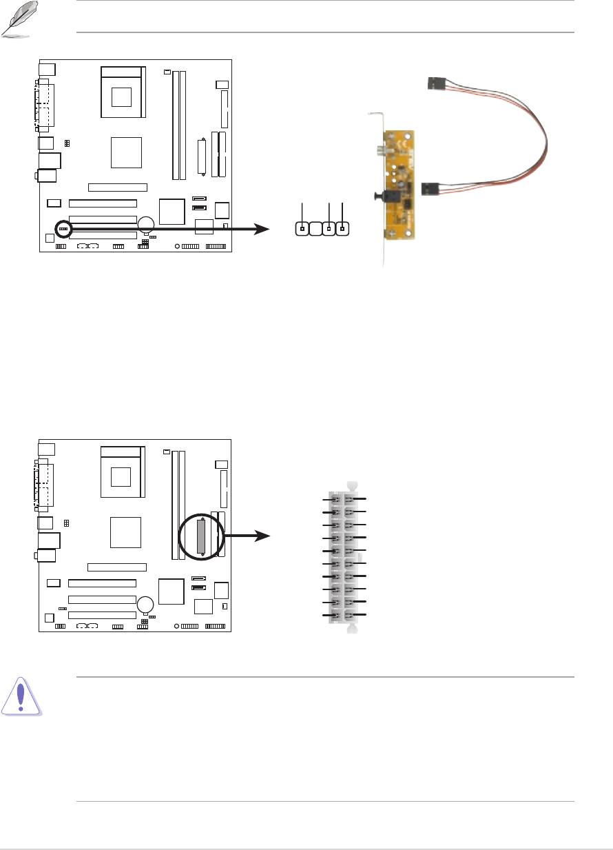
GAME/MIDI connector (16-1 pin GAME)GAME/MIDI connector (16-1 pin GAME)
GAME/MIDI connector (16-1 pin GAME)GAME/MIDI connector (16-1 pin GAME)
GAME/MIDI connector (16-1 pin GAME)
This connector is for a GAME/MIDI port. Connect the GAME/MIDI
module cable to this connector, then install the module to a slot
opening at the back of the system chassis. The GAME/MIDI port on
the module connects a joystick or a game pad for playing games, and
MIDI devices for playing or editing audio files.
The GAME/MIDI module is purchased separately.
+5V
J1B2
J1CY
GND
GND
J1CX
J1B1
+5V
A7V400-MX SE
GAME
+5V
J2B2
J2CY
J2CX
J2B1
MIDI_IN
A7V400-MX SE Game connector
MIDI_OUT
ASUS A7V400-MX SEASUS A7V400-MX SE
ASUS A7V400-MX SE
ASUS A7V400-MX SEASUS A7V400-MX SE
1-23
1-231-23
1-231-23
7.7.
7.7.
7.
Internal audio connectors (4-pin CD, AUX)Internal audio connectors (4-pin CD, AUX)
Internal audio connectors (4-pin CD, AUX)Internal audio connectors (4-pin CD, AUX)
Internal audio connectors (4-pin CD, AUX)
These connectors allow you to receive stereo audio input from sound
sources such as a CD-ROM, TV tuner, or MPEG card.
CD(Black)AUX(White)
Ground
Ground
A7V400-MX SE
Left Audio Channel
Left Audio Channel
Right Audio Channel
Right Audio Channel
A7V400-MX SE Internal audio connectors
8.8.
8.
8.8.
Front panel audio connectors (10-1 pin FP_AUDIO)Front panel audio connectors (10-1 pin FP_AUDIO)
Front panel audio connectors (10-1 pin FP_AUDIO)
Front panel audio connectors (10-1 pin FP_AUDIO)Front panel audio connectors (10-1 pin FP_AUDIO)
This connector is for the front panel audio daughterboard cable.
This connector supports the front panel audio I/O ports.
Line out_L
NC
Line out_R
MICPWR
MIC2
FP_AUDIO
A7V400-MX SE
+5VA
AGND
BLINE_OUT_L
BLINE_OUT_R
A7V400-MX SE Front panel audio connector
By default, the pins labeled LINE_OUT_R/BLINE_OUT_R and the pins
LINE_OUT_L/BLINE_OUT_L are shorted with jumper caps. Remove the
caps only when you are connecting the front panel audio cable.
1-241-24
1-24
1-241-24
Chapter 1: Product introduction
Chapter 1: Product introductionChapter 1: Product introduction
Chapter 1: Product introductionChapter 1: Product introduction
9.9.
9.9.
9.
Digital audio connector (4-1 pin SPDIF)
Digital audio connector (4-1 pin SPDIF)Digital audio connector (4-1 pin SPDIF)
Digital audio connector (4-1 pin SPDIF)Digital audio connector (4-1 pin SPDIF)
This connector is for an additional Sony/Philips Digital Interface
(S/PDIF) port(s). Connect the S/PDIF out module cable to this
connector, then install the module to a slot opening at the back of the
system chassis.
The S/PDIF module is purchased separately.
+5V
SPDIFOUT
GND
A7V400-MX SE
SPDIF
A7V400-MX SE Digital audio connector
10.10.
10.10.
10.
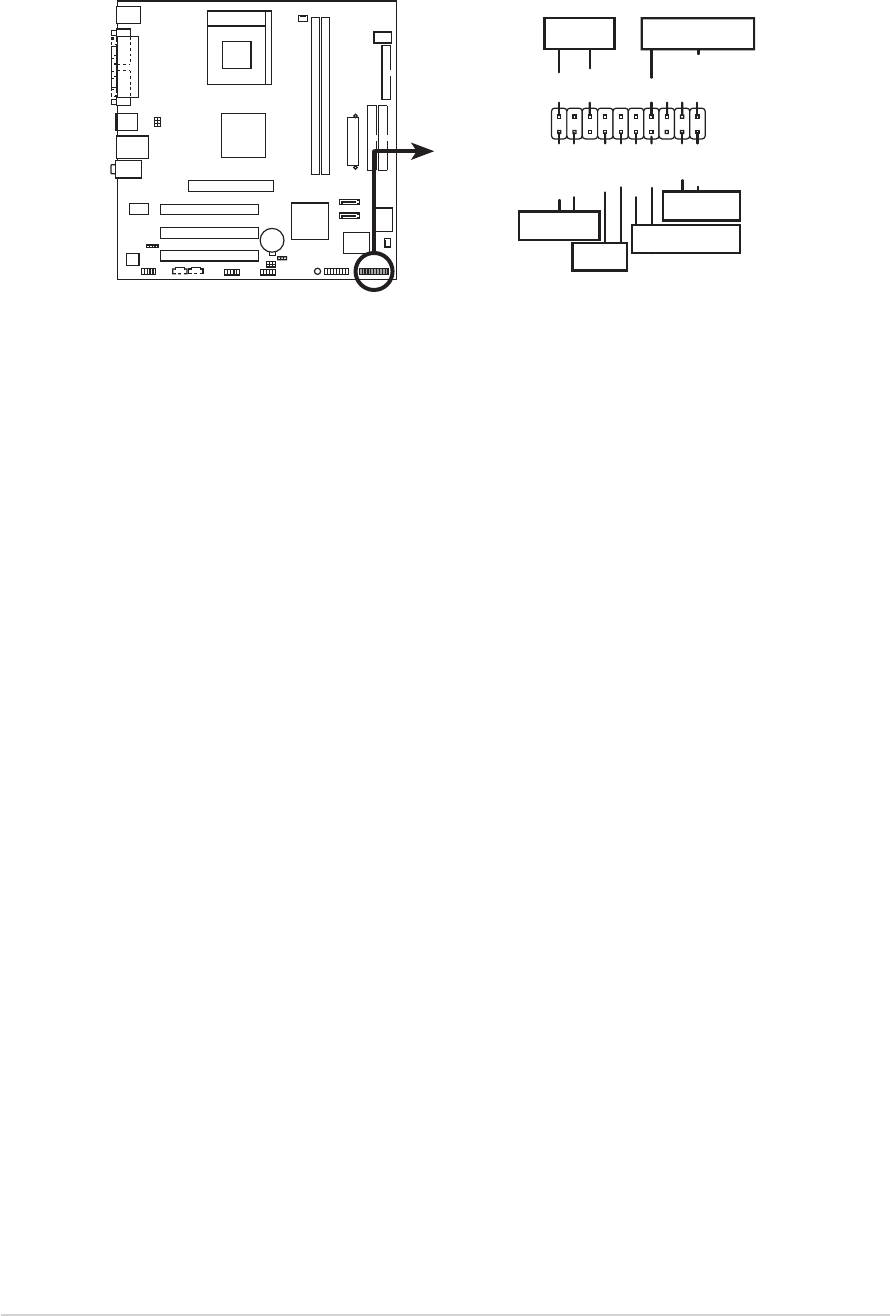
ATX power connector (20-pin ATXPWR)ATX power connector (20-pin ATXPWR)
ATX power connector (20-pin ATXPWR)ATX power connector (20-pin ATXPWR)
ATX power connector (20-pin ATXPWR)
This connector is for the 20-pin ATX power supply plug. The plug from
the power supply is designed to fit this connector in only one
orientation. Find the proper orientation and push down firmly until the
connector completely fit.
ATXPWR
+12.0VDC
+5.0VDC
+5VSB
+5.0VDC
PWR_OK
-5.0VDC
COM
COM
+5.0VDC
COM
COM
COM
+5.0VDC
PS_ON#
A7V400-MX SE
COM
COM
+3.3VDC
-12.0VDC
+3.3VDC
+3.3VDC
A7V400-MX SE ATX power connector
If you will need to replace the power supply in the future, make sure that
your new ATX 12V power supply can provide 8 A on the +12 V lead and
at least 1 A on the +5 V standby lead (+5VSB). The minimum
recommended wattage is 230W, or 300W for a fully configured system.
The system may become unstable and may experience difficulty
powering up if the power supply is inadequate.
ASUS A7V400-MX SEASUS A7V400-MX SE
ASUS A7V400-MX SE
ASUS A7V400-MX SEASUS A7V400-MX SE
1-25
1-251-25
1-251-25
11.11.
11.
11.11.
System panel connector (20-pin PANEL)System panel connector (20-pin PANEL)
System panel connector (20-pin PANEL)
System panel connector (20-pin PANEL)System panel connector (20-pin PANEL)
This connector supports several chassis-mounted functions.
SPEAKERPLED
+5 V
PLED
+5V
Ground
Ground
Speaker
Reset
ExtSMI#
Ground
Ground
Ground
HD_LED+
HD_LED-
PWRBIN
RESET
A7V400-MX SE
HDLED
PWRBTN
SMI
* Requires an ATX power supply.
A7V400-MX SE System panel connector
•
System power LED (3-pin PLED)System power LED (3-pin PLED)
System power LED (3-pin PLED)
System power LED (3-pin PLED)System power LED (3-pin PLED)
This connector is for the system power LED. Connect the chassis
power LED cable to this connector. The system power LED lights up
when you turn on the system power, and blinks when the system is in
sleep mode.
•
System warning speaker (4-pin SPEAKER)System warning speaker (4-pin SPEAKER)
System warning speaker (4-pin SPEAKER)System warning speaker (4-pin SPEAKER)
System warning speaker (4-pin SPEAKER)
This connector is for the chassis-mounted system warning speaker.
The speaker allows you to hear system beeps and warnings.
•
Reset button (2-pin RESET)
Reset button (2-pin RESET)Reset button (2-pin RESET)
Reset button (2-pin RESET)Reset button (2-pin RESET)
This connector is for the chassis-mounted reset button for system
reboot without turning off the system power.
•
ATX power button/soft-off button (2-pin PWRBTN)ATX power button/soft-off button (2-pin PWRBTN)
ATX power button/soft-off button (2-pin PWRBTN)
ATX power button/soft-off button (2-pin PWRBTN)ATX power button/soft-off button (2-pin PWRBTN)
This connector is for the system power button. Pressing the power
button turns the system on or puts the system in sleep or soft-off
mode depending on the BIOS settings. Pressing the power switch for
more than four seconds while the system is ON turns the system OFF.
•
System Management Interrupt (2-pin SMI)System Management Interrupt (2-pin SMI)
System Management Interrupt (2-pin SMI)System Management Interrupt (2-pin SMI)
System Management Interrupt (2-pin SMI)
This connector is for the chassis-mounted suspend switch that allows
you to manually place the system into a suspend mode, or “green”
mode. When in suspend mode, the system activity is instantly
decreased to save power and to expand the life of certain system
components.
•
Hard disk drive activity LED (2-pin HDLED)
Hard disk drive activity LED (2-pin HDLED)Hard disk drive activity LED (2-pin HDLED)
Hard disk drive activity LED (2-pin HDLED)Hard disk drive activity LED (2-pin HDLED)
This connector is for the HDD Activity LED. Connect the HDD Activity
LED cable to this connector. The IDE LED lights up or flashes when
data is read from or written to the HDD.
1-261-26
1-26
1-261-26
Chapter 1: Product introduction
Chapter 1: Product introductionChapter 1: Product introduction
Chapter 1: Product introductionChapter 1: Product introduction
Оглавление
- Product
- BIOS setup
- Software
