Asus A7V600: BIOS setup
BIOS setup: Asus A7V600
This chapter tells how to change
the system settings through the BIOS
Setup menus. Detailed descriptions
of the BIOS parameters are also
provided.
BIOS setup
2

2.1 Managing and updating your BIOS
The following utilities allow you to manage and update the motherboard
Basic Input/Output System (BIOS) setup.
1.
AwardBIOS Flash Utility AwardBIOS Flash Utility
AwardBIOS Flash Utility (Updates the BIOS in DOS mode using a
AwardBIOS Flash Utility AwardBIOS Flash Utility
bootable floppy disk.)
2.
ASUS CrashFree BIOS ASUS CrashFree BIOS
ASUS CrashFree BIOS ASUS CrashFree BIOS
ASUS CrashFree BIOS (Updates the BIOS using a floppy disk when the
BIOS file fails or gets corrupted.)
3.
ASUS EZ Flash (Updates the BIOS in DOS mode using a floppy disk.)
ASUS EZ Flash ASUS EZ Flash
ASUS EZ Flash ASUS EZ Flash
®
4.
ASUS Update ASUS Update
ASUS Update ASUS Update
ASUS Update (Updates the BIOS in Windows
environment.)
Refer to the corresponding sections for details on these utilities.
Save a copy of the original motherboard BIOS file to a floppy disk in case
you need to restore the BIOS in the future. Copy the original
motherboard BIOS using the ASUS Update or AwardBIOS Flash utilities.
2.1.12.1.1
2.1.12.1.1
2.1.1
Creating a bootable floppy diskCreating a bootable floppy disk
Creating a bootable floppy diskCreating a bootable floppy disk
Creating a bootable floppy disk
1. Do either one of the following to create a bootable floppy disk.
DOS environmentDOS environment
DOS environmentDOS environment
DOS environment
a. Insert a 1.44MB floppy disk into the drive.
b. At the DOS prompt, type format A:/S
then press <Enter>.
®®
®®
®
WindowsWindows
WindowsWindows
Windows
XP environment XP environment
XP environment XP environment
XP environment
a. Insert a 1.44 MB floppy disk to the floppy disk drive.
®
b. Click
Start from the Windows
Start Start
Start Start
desktop, then select
MyMy
MyMy
My
ComputerComputer
ComputerComputer
Computer.
c. Select the 3 1/2 Floppy Drive icon.
d. Click
File from the menu, then select
File File
File File
Format. A
FormatFormat
FormatFormat
Format 3 1/2Format 3 1/2
Format 3 1/2Format 3 1/2
Format 3 1/2
Floppy DiskFloppy Disk
Floppy DiskFloppy Disk
Floppy Disk window appears.
e. Select
Create an MS-DOS startup disk Create an MS-DOS startup disk
Create an MS-DOS startup disk Create an MS-DOS startup disk
Create an MS-DOS startup disk from the format
options field, then click
Start.
StartStart
StartStart
®
®®
®®
Windows
WindowsWindows
WindowsWindows
2000 environment 2000 environment
2000 environment 2000 environment
2000 environment
®
To create a set of boot disks for Windows
2000:
a. Insert a formatted, high density 1.44 MB floppy disk into the drive.
®
b. Insert the Windows
2000 CD to the optical drive.
c. Click
StartStart
StartStart
Start, then select
RunRun
RunRun
Run.
d. From the Open field, type
D:\bootdisk\makeboot a:
assuming that D: is your optical drive.
e. Press <Enter>, then follow screen instructions to continue.
2. Copy the original or the latest motherboard BIOS file to the bootable
floppy disk.
2-2
2-22-2
2-22-2
Chapter 2: BIOS setupChapter 2: BIOS setup
Chapter 2: BIOS setupChapter 2: BIOS setup
Chapter 2: BIOS setup
2.1.22.1.2
2.1.22.1.2
2.1.2
AwardBIOS Flash UtilityAwardBIOS Flash Utility
AwardBIOS Flash UtilityAwardBIOS Flash Utility
AwardBIOS Flash Utility
You may update the Basic Input/Output System (BIOS) using a bootable
floppy disk with the executable AwardBIOS Flash utility (AWDFLASH.EXE).
To update the BIOS using the AwardBIOS Flash Utility:
1. Download the latest BIOS file from the ASUS website. Rename the file
to *.BIN, then save it to the bootable floppy disk you created earlier.
Save only the updated BIOS file in the floppy disk to avoid loading a
wrong BIOS file.
2. Copy the AWDFLASH.EXE utility from the support CD to the floppy disk.
3. Boot the computer from the floppy disk drive.
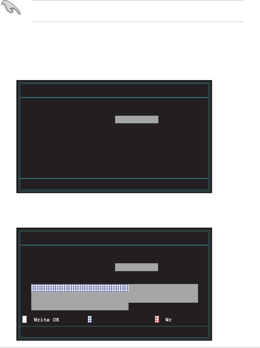
4. When the prompt (A:) appears, type
awdflash.exe, then press
awdflash.exeawdflash.exe
awdflash.exeawdflash.exe
<Enter>
to display the AwardBIOS Flash Utility screen. The utility
automatically checks the new BIOS file on the floppy disk.
AwardBIOS Flash Utility for ASUS V1.09
(C) Phoenix Technologies Ltd. All Rights Reserved
For KM400-8237-A7V400SE-00 DATE: 01/06/2005
Flash Type - SST 39SF020 /5V
File Name to Program : a7v4se02.bin
Message: Please Wait!
5. After verification, the utility updates the BIOS file. Do not shut down
the computer during the updating process. The computer returns to
POST after updating the BIOS file.
AwardBIOS Flash Utility for ASUS V1.09
(C) Phoenix Technologies Ltd. All Rights Reserved
For KM400-8237-A7V400SE-00 DATE: 01/06/2005
Flash Type - SST 39SF020 /5V
File Name to Program : a7v4se02.bin
Program Flashing Memory - 0FE00 OK
Warning: Don’t Turn OFF Power Or Reset System!
ASUS A7V400-MX SEASUS A7V400-MX SE
ASUS A7V400-MX SE
ASUS A7V400-MX SEASUS A7V400-MX SE
2-3
2-32-3
2-32-3
123
1
2
3
1
2
3
123
Write OK
123
1
2
3
1
2
3
123
No Update
123
1
2
3
1
2
3
123
Write Fail
123456789012345678901234567890121234567890123
1
2345678901234567890123456789012123456789012
3
1
2345678901234567890123456789012123456789012
3
123456789012345678901234567890121234567890123

2.1.32.1.3
2.1.32.1.3
2.1.3
ASUS CrashFree BIOS utilityASUS CrashFree BIOS utility
ASUS CrashFree BIOS utilityASUS CrashFree BIOS utility
ASUS CrashFree BIOS utility
The ASUS CrashFree BIOS allows you to update the BIOS file when it fails or
gets corrupted. You can update a corrupted BIOS file using a floppy disk
that contains the updated BIOS file and the AWDFLASH utility.
Before using this utility, prepare the bootable floppy disk containing the
updated motherboard BIOS and the AWDFLASH.EXE utility. The
AWDFLASH.EXE utility is available from the support CD.
To update the BIOS using CrashFree BIOS:
1. Turn on the system.
2. When prompted, place the floppy disk with the updated BIOS file and
the AWDFLASH.EXE utility to the floppy disk drive.
3. The AwardBIOS Flash Utility window appears. Follow the instructions in
the previous section to update the BIOS.
Before using the ASUS CrashFree BIOS feature on this motherboard, you
must install an AGP or PCI VGA card to one of the expansion slots before
you turn on the computer. Motherboards with onboard VGA (such as
A7V400-MX SE) do not display the screen when the BIOS crashes even
after you reboot the computer.
2.1.42.1.4
2.1.4
2.1.42.1.4
ASUS EZ Flash utility
ASUS EZ Flash utilityASUS EZ Flash utility
ASUS EZ Flash utilityASUS EZ Flash utility
The ASUS EZ Flash feature allows you to update the BIOS without having to
go through the long process of booting from a floppy disk and using a
DOS-based utility. The EZ Flash utility is built-in the BIOS chip so it is
accessible by pressing <Alt> + <F2> during the Power-On Self Tests (POST).
Before using this utility, prepare the floppy disk containing the updated
motherboard BIOS.
To update the BIOS using EZ Flash:
1. Insert the floppy disk with the updated BIOS file to the floppy disk
drive, then turn on the system.
2. Press <Alt> + <F2> during POST to display the AwardBIOS Flash Utility
screen.
3. Follow the instructions in section “2.1.2 Award BIOS Flash Utility” to
update the BIOS.
After updating the BIOS file using the AwardBIOS Flash Utility, ASUS
CrashFree BIOS, or ASUS EZ Flash, enter the BIOS Setup and load the
default values using the Exit Menu. See section “2.7 Exit menu” for details.
2-42-4
2-4
2-42-4
Chapter 2: BIOS setup
Chapter 2: BIOS setupChapter 2: BIOS setup
Chapter 2: BIOS setupChapter 2: BIOS setup
2.1.52.1.5
2.1.52.1.5
2.1.5
ASUS Update utilityASUS Update utility
ASUS Update utilityASUS Update utility
ASUS Update utility
The ASUS Update is a utility that allows you to manage, save, and update
®
the motherboard BIOS in Windows
environment. The ASUS Update utility
allows you to:
• Save the current BIOS file
• Download the latest BIOS file from the Internet
• Update the BIOS from an updated BIOS file
• Update the BIOS directly from the Internet, and
• View the BIOS version information.
This utility is available in the support CD that comes with the motherboard package.
Installing ASUS Update
Installing ASUS UpdateInstalling ASUS Update
Installing ASUS UpdateInstalling ASUS Update
To install ASUS Update:
1. Place the support CD in the optical drive. The
Drivers Drivers
Drivers Drivers
Drivers menu appears.
2. Click the
Utilities Utilities
Utilities Utilities
Utilities tab, then click
ASUS Update. See page 3-3 for
ASUS UpdateASUS Update
ASUS UpdateASUS Update
the
Utilities Utilities
Utilities Utilities
Utilities screen menu.
3. The ASUS Update utility is copied to your system.
• ASUS Update requires an Internet connection either through a
network or an Internet Service Provider (ISP).
®
• Quit all Windows
applications before you update the BIOS using this utility.
Updating the BIOS through the InternetUpdating the BIOS through the Internet
Updating the BIOS through the InternetUpdating the BIOS through the Internet
Updating the BIOS through the Internet
To update the BIOS through the Internet:
®
1. Launch the ASUS Update utility from the Windows
desktop by clicking
Start Start
Start Start
Start >
Programs Programs
Programs >
Programs Programs
ASUS >
ASUS ASUS
ASUS ASUS
ASUSUpdate >
ASUSUpdate ASUSUpdate
ASUSUpdate ASUSUpdate
ASUSUpdate. The
ASUSUpdateASUSUpdate
ASUSUpdateASUSUpdate
ASUS Update main window appears.
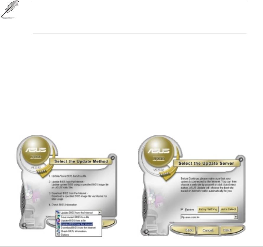
2. Select
Update BIOS from
Update BIOS fromUpdate BIOS from
Update BIOS fromUpdate BIOS from
3. Select the ASUS FTP site
the Internet the Internet
the Internet the Internet
the Internet option from the
nearest you to avoid network
drop-down menu, then click
traffic, or click
Auto SelectAuto Select
Auto SelectAuto Select
Auto Select.
NextNext
NextNext
Next.
Click
NextNext
Next.
NextNext
ASUS A7V400-MX SEASUS A7V400-MX SE
ASUS A7V400-MX SE
ASUS A7V400-MX SEASUS A7V400-MX SE
2-5
2-52-5
2-52-5
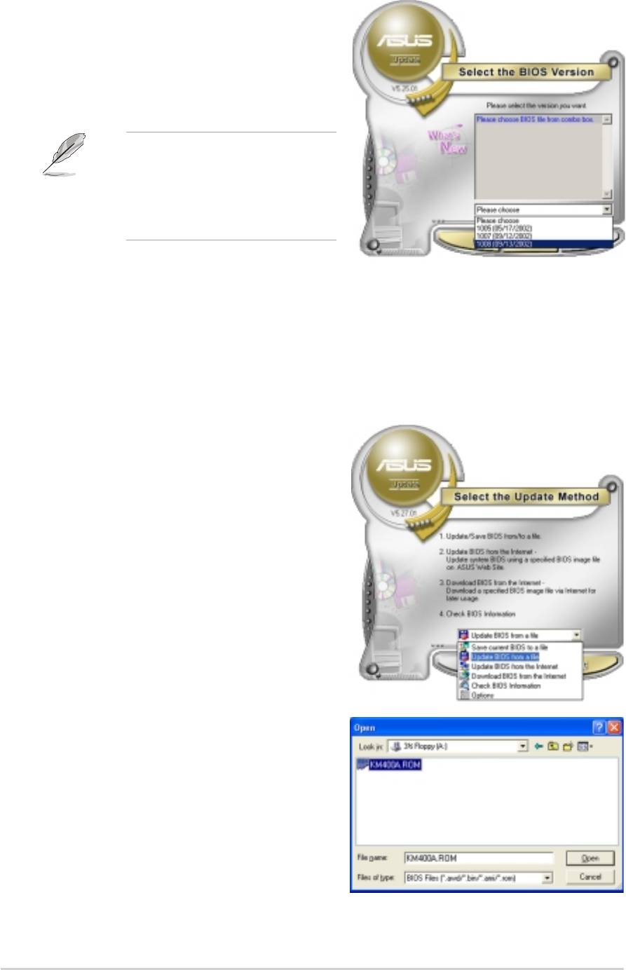
4. From the FTP site, select the
BIOS version that you wish to
download. Click Next.
5. Follow the screen instructions to
complete the update process.
The ASUS Update utility is
capable of updating itself
through the Internet. Always
update the utility to avail all
its features.
Updating the BIOS through a BIOS fileUpdating the BIOS through a BIOS file
Updating the BIOS through a BIOS fileUpdating the BIOS through a BIOS file
Updating the BIOS through a BIOS file
To update the BIOS through a BIOS file:
®
1. Launch the ASUS Update utility from the Windows
desktop by
clicking
Start >
Start Start
Start Start
Programs >
Programs Programs
Programs Programs
ASUS ASUS
ASUS ASUS
ASUS >
ASUSUpdate ASUSUpdate
ASUSUpdate ASUSUpdate
ASUSUpdate >
ASUSUpdate. The ASUS Update main window appears.
ASUSUpdateASUSUpdate
ASUSUpdateASUSUpdate
2. Select
Update BIOS from aUpdate BIOS from a
Update BIOS from aUpdate BIOS from a
Update BIOS from a
file option from the drop-down
file file
file file
menu, then click
Next.
NextNext
NextNext
3. Locate the BIOS file from the
Open window, then click
Open Open
Open Open
SaveSave
SaveSave
Save.
4. Follow the screen instructions to
complete the update process.
2-62-6
2-6
2-62-6
Chapter 2: BIOS setup
Chapter 2: BIOS setupChapter 2: BIOS setup
Chapter 2: BIOS setupChapter 2: BIOS setup

2.2 BIOS beep codes
When you turn the power on and the system runs POST (Power On Self
Tests), you will hear BIOS beeps. Refer to the following table for the
meaning of the beeps.
Award BIOS beep codesAward BIOS beep codes
Award BIOS beep codes
Award BIOS beep codesAward BIOS beep codes
BeepBeep
BeepBeep
Beep
MeaningMeaning
MeaningMeaning
Meaning
One short beep whenOne short beep when
One short beep whenOne short beep when
One short beep when No error during POST
displaying logodisplaying logo
displaying logo
displaying logodisplaying logo
Long beeps in an endless loopLong beeps in an endless loop
Long beeps in an endless loopLong beeps in an endless loop
Long beeps in an endless loop No DRAM installed or detected
One long beep followed byOne long beep followed by
One long beep followed byOne long beep followed by
One long beep followed by Video card not found or
three short beepsthree short beeps
three short beeps video card memory bad
three short beepsthree short beeps
High frequency beeps whenHigh frequency beeps when
High frequency beeps when CPU overheated; System running at a
High frequency beeps whenHigh frequency beeps when
system is working lower frequency
system is workingsystem is working
system is workingsystem is working
2.3 BIOS setup program
This motherboard supports a programmable low pin count (LPC) chip that
you can update using the provided utility described in section
“
2.1 Managing and updating your BIOS.”
Use the BIOS Setup program when you are installing a motherboard,
reconfiguring your system, or prompted to “Run Setup.” This section
explains how to configure your system using this utility.
Even if you are not prompted to use the Setup program, you can change
the configuration of your computer in the future. For example, you can
enable the security password feature or change the power management
settings. This requires you to reconfigure your system using the BIOS
Setup program so that the computer can recognize these changes and
record them in the CMOS RAM of the firmware hub.
The firmware hub on the motherboard stores the Setup utility. When you
start up the computer, the system provides you with the opportunity to
run this program. Press <Del>
during the Power-On-Self-Test (POST) to
enter the Setup utility; otherwise, POST continues with its test routines.
If you wish to enter Setup after POST, restart the system by pressing
<Ctrl+Alt+Delete>, or by pressing the reset button on the system chassis.
You can also restart by turning the system off and then back on. Do this
last option only if the first two failed.
The Setup program is designed to make it as easy to use as possible. Being
a menu-driven program, it lets you scroll through the various sub-menus
and make your selections from the available options using the navigation
keys.
ASUS A7V400-MX SEASUS A7V400-MX SE
ASUS A7V400-MX SE
ASUS A7V400-MX SEASUS A7V400-MX SE
2-7
2-72-7
2-72-7

• The default BIOS settings for this motherboard apply for most
conditions to ensure optimum performance. If the system becomes
unstable after changing any BIOS settings, load the default settings to
ensure system compatibility and stability. Select the
Load Default
Load DefaultLoad Default
Load DefaultLoad Default
SettingsSettings
SettingsSettings
Settings item under the Exit Menu. See section “2.7 Exit Menu.”
• The BIOS setup screens shown in this section are for reference purposes
only, and may not exactly match what you see on your screen.
• Visit the ASUS website (www.asus.com) to download the latest BIOS
file for this motherboard.
2.3.12.3.1
2.3.12.3.1
2.3.1
BIOS menu bar
BIOS menu barBIOS menu bar
BIOS menu barBIOS menu bar
The top of the screen has a menu bar with the following selections:
MAINMAIN
MAINMAIN
MAIN Use this menu to make changes to the basic system
configuration.
ADVANCEDADVANCED
ADVANCEDADVANCED
ADVANCED Use this menu to enable and make changes to the
advanced features.
POWERPOWER
POWERPOWER
POWER Use this menu to configure and enable Power
Management features.
BOOTBOOT
BOOTBOOT
BOOT Use this menu to configure the default system device
used to locate and load the Operating System.
EXIT Use this menu to exit the current menu or to exit the
EXITEXIT
EXITEXIT
Setup program.
To access the menu bar items, press the right or left arrow key on the
keyboard until the desired item is highlighted.
2.3.2
2.3.22.3.2
2.3.22.3.2
Legend bar
Legend barLegend bar
Legend barLegend bar
At the bottom of the Setup screen is a legend bar. The keys in the legend
bar allow you to navigate through the various setup menus. The following
table lists the legend bar keys and their corresponding functions.
Navigation KeyNavigation Key
Navigation KeyNavigation Key
Navigation Key
FunctionFunction
Function
FunctionFunction
<F1> Displays the General Help screen
<F2> Navigates the Item Specific Help screen
<F5> Loads previous values
<Esc> Jumps to the Exit menu or returns to the main menu
from a sub-menu
Left or Right arrow Selects the menu item to the left or right
Up or Down arrow Moves the highlight up or down between fields
Page Down or – (minus) Scrolls backward through the values for the highlighted field
Page Up or + (plus) Scrolls forward through the values for the highlighted field
<Enter> Brings up a selection menu for the highlighted field
<F10> Saves changes and exit
2-82-8
2-8
2-82-8
Chapter 2: BIOS setup
Chapter 2: BIOS setupChapter 2: BIOS setup
Chapter 2: BIOS setupChapter 2: BIOS setup

General helpGeneral help
General helpGeneral help
General help
In addition to the Item Help window, the BIOS setup program also provides
a General Help screen. You may launch this screen from any menu by
simply pressing <F1>. The General Help screen lists the legend keys and
their corresponding functions.
Scroll bar
Scroll barScroll bar
Scroll barScroll bar
When a scroll bar appears to the right of a help window, it indicates that
there is more information to be displayed that will not fit in the window. Use
<PgUp> and <PgDn> or the up and down arrow keys to scroll through the
entire help document. Press <Home> to display the first page, press <End>
to go to the last page. To exit the help window, press <Enter> or <Esc>.
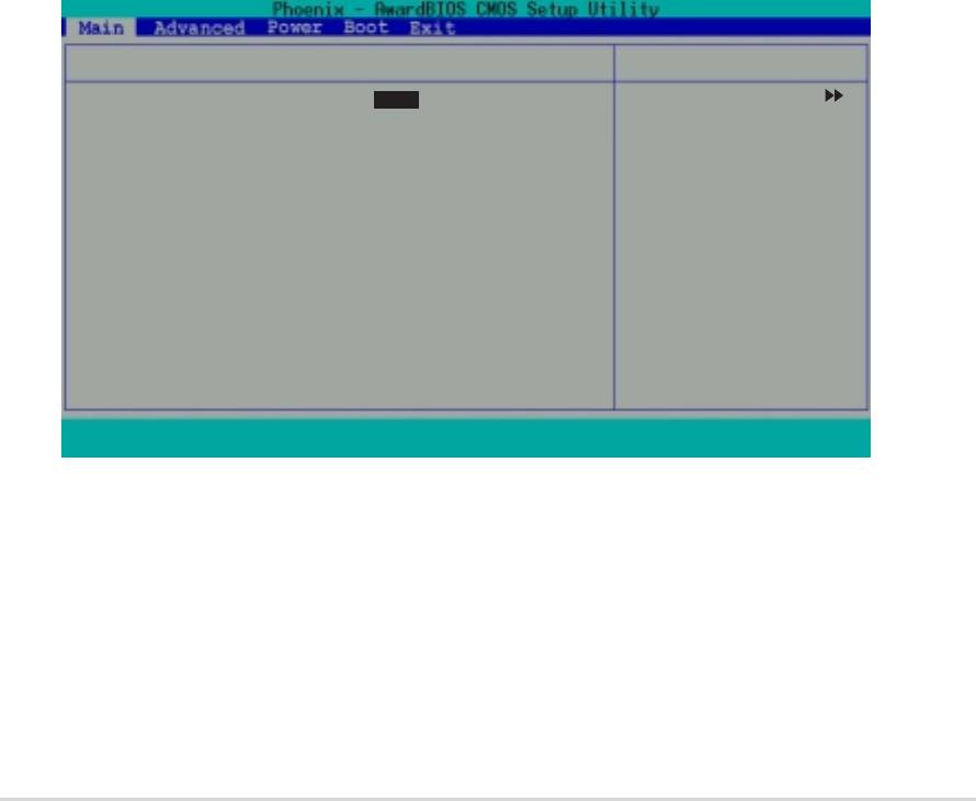
Sub-menuSub-menu
Sub-menu
Sub-menuSub-menu
The right pointer symbol that appears at the
left of certain parameters indicates that a
System Time
sub-menu exists for this field. A sub-menu
System Date
offers additional parameter options. To
Legacy Diskette A:
display a sub-menu, move the highlight to the
Primary IDE Master
field and press <Enter>. The sub-menu
Primary IDE Slave
Secondary IDE Master
appears. Use the legend keys to navigate and
Secondary IDE Slave
First SATA Master
enter values within each sub-menu as you
Second SATA Master
would within a menu. Use the <Esc> key to
Installed Memory
return to the main menu. Take some time to
familiarize yourself with the legend keys and
their corresponding functions. Practice
navigating through the various menus and
F1 : Help
↑
↑↑
↑↑
↓↓
↓↓
↓ : Select Ite
sub-menus. While moving around through the
ESC : Exit
→←→←
→←→←
→←: Select Men
Setup program, note that explanations appear in the Item Help window
located to the right of each menu. This window displays the help text for
the highlighted field.
Saving changes and exiting the Setup program
Saving changes and exiting the Setup programSaving changes and exiting the Setup program
Saving changes and exiting the Setup programSaving changes and exiting the Setup program
See “2.8 Exit menu” for detailed information on saving changes and exiting
the setup program.
ASUS A7V400-MX SEASUS A7V400-MX SE
ASUS A7V400-MX SE
ASUS A7V400-MX SEASUS A7V400-MX SE
2-9
2-92-9
2-92-9

2.4 Main menu
System Time 15 : 30 : 30
Select Menu
System Date Wed, Jan 05 2003
Item Specific Help
Legacy Diskette A: [1.44M, 3.5 in.]
Change the internal
Primary IDE Master [ST321122A]
clock.
Primary IDE Slave [ASUS CDS520/A]
Secondary IDE Master [None]
Secondary IDE Slave [None]
First SATA Master [None]
Second SATA Master [None]
Installed Memory 256MB
F1 : Help
↑↑
↑↑
↑
↓ : Select Item -/+ : Change Value F5 : Setup Defaults
↓↓
↓↓
ESC : Exit
→←: Select Menu Enter : Select Submenu F10: Save and Exit
→←→←
→←→←
System Time [hh:mm:ss]
System Time [hh:mm:ss]System Time [hh:mm:ss]
System Time [hh:mm:ss]System Time [hh:mm:ss]
Sets the system to the time that you specify (usually the current time).
The format is hour, minute, second. Valid values for hour, minute and
second are Hour: (00 to 23), Minute: (00 to 59), Second: (00 to 59). Use
the <Tab> key to move between the hour, minute, and second fields.
System Date [day, mm dd yyyy]System Date [day, mm dd yyyy]
System Date [day, mm dd yyyy]
System Date [day, mm dd yyyy]System Date [day, mm dd yyyy]
Sets the system to the date that you specify (usually the current date).
The format is month, day, year. Valid values for month, day, and year are
Month: (1 to 12), Day: (1 to 31), Year: (1999 to 2099). Use the <Tab>
key to move between the month, day, and year fields.
Legacy Diskette A [1.44M, 3.5 in.]
Legacy Diskette A [1.44M, 3.5 in.]Legacy Diskette A [1.44M, 3.5 in.]
Legacy Diskette A [1.44M, 3.5 in.]Legacy Diskette A [1.44M, 3.5 in.]
Sets the type of floppy drive installed. Configuration options: [None]
[360K, 5.25 in.] [1.2M , 5.25 in.] [720K , 3.5 in.] [1.44M, 3.5 in.]
[2.88M, 3.5 in.]
Installed Memory [XXX MB]Installed Memory [XXX MB]
Installed Memory [XXX MB]
Installed Memory [XXX MB]Installed Memory [XXX MB]
This field automatically displays the amount of conventional memory
detected by the system during the boot process.
2-102-10
2-10
2-102-10
Chapter 2: BIOS setup
Chapter 2: BIOS setupChapter 2: BIOS setup
Chapter 2: BIOS setupChapter 2: BIOS setup

Primary/Secondary IDE Master/SlavePrimary/Secondary IDE Master/Slave
Primary/Secondary IDE Master/SlavePrimary/Secondary IDE Master/Slave
Primary/Secondary IDE Master/Slave
Primary IDE Master
Select Menu
Primary IDE Master [Auto]
Item Specific Help
Access Mode [Auto]
Press [Enter] to
Capacity 40020 MB
select.
Cylinder 19158
Head 16
Sector 255
PIO Mode [Auto]
UDMA Mode [Auto]
Transfer Mode UDMA 5
F1 : Help
↑↑
↑↑
↑
↓↓
↓ : Select Item -/+ : Change Value F5 : Setup Defaults
↓↓
ESC : Exit
→←→←
→←: Select Menu Enter : Select Submenu F10: Save and Exit
→←→←
Primary IDE Master/Slave [Auto]Primary IDE Master/Slave [Auto]
Primary IDE Master/Slave [Auto]Primary IDE Master/Slave [Auto]
Primary IDE Master/Slave [Auto]
Secondary IDE Master/Slave [Auto]Secondary IDE Master/Slave [Auto]
Secondary IDE Master/Slave [Auto]Secondary IDE Master/Slave [Auto]
Secondary IDE Master/Slave [Auto]
Select [Auto] to automatically detect an IDE hard disk drive. If automatic
detection is successful, the setup BIOS automatically fills in the correct
values for the remaining fields on this sub-menu. If automatic detection
fails, this may be because the hard disk drive is too old or too new. If the
hard disk was already formatted on a previous system, the setup BIOS may
detect incorrect parameters. In these cases, select [Manual] to manually
enter the IDE hard disk drive parameters. If no drive is installed or if you are
removing a drive and not replacing it, select [None].
Configuration options: [None] [Auto] [Manual]
Access Mode [Auto]
Access Mode [Auto]Access Mode [Auto]
Access Mode [Auto]Access Mode [Auto]
The default [Auto] automatically detects an IDE hard disk drive. Select
[CHS] in coordination with the [Manual] setting of the Primary IDE Master in
to manually enter the hard disk drive values.
Before attempting to configure a hard disk drive, make sure you have
the correct configuration information supplied by the drive
manufacturer. Incorrect settings may cause the system to fail to
recognize the installed hard disk.
ASUS A7V400-MX SEASUS A7V400-MX SE
ASUS A7V400-MX SE
ASUS A7V400-MX SEASUS A7V400-MX SE
2-11
2-112-11
2-112-11

[Manual] and [CHS] Settings[Manual] and [CHS] Settings
[Manual] and [CHS] Settings[Manual] and [CHS] Settings
[Manual] and [CHS] Settings
Primary IDE Master
Select Menu
Primary IDE Master [Manual]
Item Specific Help
Access Mode [CHS]
Press [Enter] to
Capacity 40020 MB
select sector
addressing method.
Cylinder [19158]
Head [ 16]
Sector [ 255]
PIO Mode [ Auto]
UDMA Mode [ Auto]
Transfer Mode UDMA 4
F1 : Help
↑↑
↑
↑↑
↓
↓↓
↓↓
: Select Item -/+ : Change Value F5 : Setup Defaults
ESC : Exit
→←→←
→←
→←→←
: Select Menu Enter : Select Sub-menu F10 : Save and Exit
Manually enter the number of cylinders, heads and sectors per track for the
drive. Refer to the drive documentation or the drive label for this information.
After entering the IDE hard disk drive information into BIOS, use a disk
utility, such as FDISK, to partition and format new IDE hard disk drives. This
is necessary so that you can write or read data from the hard disk. Make
sure to set the partition of the Primary IDE hard disk drives to active.
After making your selections on this sub-menu, press the <Esc> key to
return to the Main menu. The Main menu displays the hard disk drive field
with your configuration.
Access Mode [Auto]Access Mode [Auto]
Access Mode [Auto]Access Mode [Auto]
Access Mode [Auto]
Select the hard disk drive type from this field. When Logical Block
Addressing (LBA) is enabled, the 28-bit addressing of the hard drive is
used without regard for cylinders, heads, or sectors. Note that LBA Mode is
necessary for drives with more than 504 MB storage capacity. Select [CHS]
to make manual entries for configuring the fields below.
Configuration options: [CHS] [LBA] [Large] [Auto]
Capacity
CapacityCapacity
CapacityCapacity
Displays the hard disk drive capacity in MB or GB. This item is non-configurable.
CylinderCylinder
Cylinder
CylinderCylinder
Configures the number of cylinders. Refer to the drive documentation to
determine the correct value.
2-122-12
2-12
2-122-12
Chapter 2: BIOS setup
Chapter 2: BIOS setupChapter 2: BIOS setup
Chapter 2: BIOS setupChapter 2: BIOS setup
HeadHead
HeadHead
Head
Configures the number of read/write heads. Refer to the drive documentation
to determine the correct value. To make changes to this field, set the IDE
Primary Master field to [Manual]
and the Access Mode
to [CHS].
Sector
SectorSector
SectorSector
Configures the number of sectors per track. Refer to the drive
documentation to determine the correct value.
PIO ModePIO Mode
PIO ModePIO Mode
PIO Mode
Sets the PIO mode. Configuration options: [Auto] [Mode 0] [Mode 1]
[Mode 2] [Mode 3] [Mode 4]
UDMA Mode
UDMA ModeUDMA Mode
UDMA ModeUDMA Mode
Sets the UDMA transfer mode. Configuration options: [Disabled] [Auto]
Transfer ModeTransfer Mode
Transfer ModeTransfer Mode
Transfer Mode
Sets the transfer mode. Configuration options: [Auto] [UDMA0] [UDMA1]
[UDMA2] [UDMA3] [UDMA4] [UDMA5]
First/Second SATA Master
First/Second SATA MasterFirst/Second SATA Master
First/Second SATA MasterFirst/Second SATA Master
First SATA Master
Select Menu
Extended IDE Drive [Auto]
Item Specific Help
Access Mode [Auto]
Press [Enter] to
Capacity 82 GB
select.
Cylinder 39420
Head 16
Precomp 0
Landing Zone 39419
Sector 255
F1 : Help
↑
↑↑
↑↑
↓ : Select Item -/+ : Change Value F5 : Setup Defaults
↓↓
↓↓
ESC : Exit
→←: Select Menu Enter : Select Submenu F10: Save and Exit
→←→←
→←→←
Extended IDE Drive [Auto]
Extended IDE Drive [Auto]Extended IDE Drive [Auto]
Extended IDE Drive [Auto]Extended IDE Drive [Auto]
Sets the installed SATA hard disk drive as an extended IDE drive.
Configuration options: [Auto] [None]
Access Mode [Auto]
Access Mode [Auto]Access Mode [Auto]
Access Mode [Auto]Access Mode [Auto]
The default [Auto] enables or disables the LBA mode for the SATA hard
disk drive. Configuration options: [Auto] [Large]
ASUS A7V400-MX SEASUS A7V400-MX SE
ASUS A7V400-MX SE
ASUS A7V400-MX SEASUS A7V400-MX SE
2-13
2-132-13
2-132-13

CapacityCapacity
CapacityCapacity
Capacity
Refer to the previous section.
Cylinder
CylinderCylinder
CylinderCylinder
Refer to the previous section.
Head
HeadHead
HeadHead
Refer to the previous section.
PrecompPrecomp
PrecompPrecomp
Precomp
Displays the precompressed volumes on the hard disk drive (in MB), if any.
Landing Zone
Landing ZoneLanding Zone
Landing ZoneLanding Zone
Displays the drive’s maximum useable capacity as calculated by the BIOS
based on the drive information you entered.
SectorSector
SectorSector
Sector
Refer to the previous section.
2-142-14
2-14
2-142-14
Chapter 2: BIOS setup
Chapter 2: BIOS setupChapter 2: BIOS setup
Chapter 2: BIOS setupChapter 2: BIOS setup
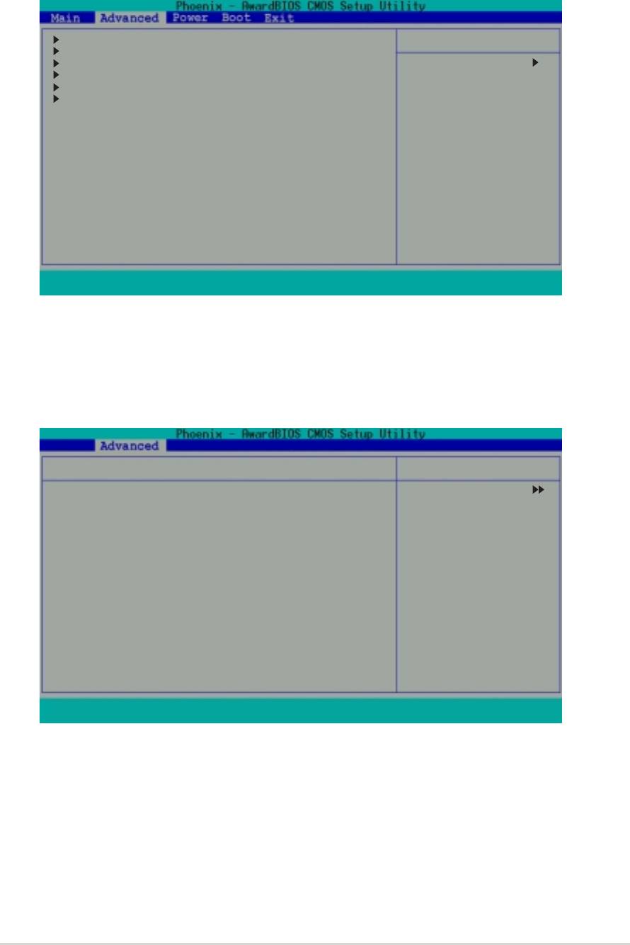
2.5 Advanced menu
The Advanced menu items allow you to change the settings for the CPU
and other system devices.
CPU Configuration
Select Menu
Memory Configuration
Chipset
Item Specific Help
PCIPnP
Onboard Devices Configuration
Press [Enter] to set.
USB Configuration
F1 : Help
↑↑
↑↑
↑
↓ : Select Item -/+ : Change Value F5 : Setup Defaults
↓↓
↓↓
ESC : Exit
→←→←
→←→←
→←: Select Menu Enter : Select Submenu F10: Save and Exit
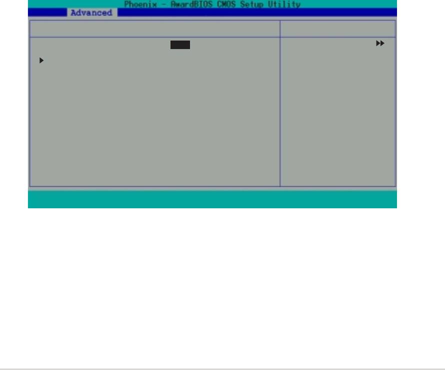
2.5.12.5.1
2.5.12.5.1
2.5.1
CPU Configuration
CPU ConfigurationCPU Configuration
CPU ConfigurationCPU Configuration
This menu displays the CPU type, speed, cache RAM, and current front side
bus frequency auto-detected by the BIOS.
CPU Configuration
Select Menu
CPU Type AMD Athlon(tm)
Item Specific Help
CPU Speed 750MHz
Cache RAM 256K
Current FSB Frequency 100MHz
F1 : Help
↑↑
↑↑
↑
↓
↓↓
↓↓
: Select Item -/+ : Change Value F5 : Setup Defaults
ESC : Exit
→←→←
→←
→←→←
: Select Menu Enter : Select Sub-menu F10 : Save and Exit
ASUS A7V400-MX SE
ASUS A7V400-MX SEASUS A7V400-MX SE
ASUS A7V400-MX SEASUS A7V400-MX SE
2-15
2-152-15
2-152-15

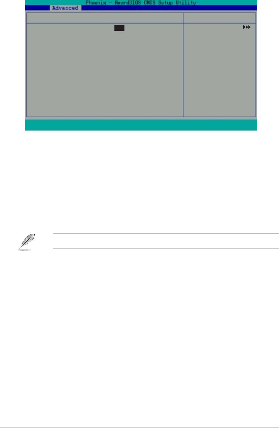
2.5.22.5.2
2.5.22.5.2
2.5.2
Memory Configuration
Memory ConfigurationMemory Configuration
Memory ConfigurationMemory Configuration
This menu allows you to change the system memory settings.
Memory Configuration
Select Menu
Current DRAM Frequency 133MHz
Item Specific Help
DRAM Clock [By SPD]
DRAM Timing [Auto by SPD]
Set DRAM frequency.
DRAM CAS Latency 2.5
Bank Interleave Disabled
Pre-charge to Active (Trp) 5T
Active to Precharge (Tras) 7T
Active to CMD (Trcd) 5T
DRAM Burst Length [4]
DRAM Command Rate [2T Command]
Write Recovery Time [3T]
tWTR [2T]
F1 : Help
↑↑
↑↑
↑
↓↓
↓↓
↓
: Select Item -/+ : Change Value F5 : Setup Defaults
ESC : Exit
→←→←
→←→←
→←
: Select Menu Enter : Select Sub-menu F10 : Save and Exit
Current DRAM Frequency [XXX MHz]Current DRAM Frequency [XXX MHz]
Current DRAM Frequency [XXX MHz]Current DRAM Frequency [XXX MHz]
Current DRAM Frequency [XXX MHz]
Displays the current memory frequency as auto-detected by the BIOS.
DRAM Clock [By SPD]DRAM Clock [By SPD]
DRAM Clock [By SPD]DRAM Clock [By SPD]
DRAM Clock [By SPD]
The DRAM clock are set according to the DRAM SPD (Serial Presence
Detect). You can manually set the DRAM clock parameters.
Configuration options: [By SPD] [133 MHz] [166 MHz]
DRAM Timing [Auto by SPD]DRAM Timing [Auto by SPD]
DRAM Timing [Auto by SPD]DRAM Timing [Auto by SPD]
DRAM Timing [Auto by SPD]
It is recommended that you set this parameter to [Auto by SPD]. Setting
to [Auto by SPD] synchronizes the DRAM timing with the DRAM clock.
Setting to [Manual] allows you to set the values for DRAM CAS Latency,
Bank Interleave, Pre-charge to Active (TRP) and Active to CMD (Trcd)
prameters. Configuration options: [Manual] [Auto By SPD] [Safe]
DRAM CAS Latency [2.5]DRAM CAS Latency [2.5]
DRAM CAS Latency [2.5]DRAM CAS Latency [2.5]
DRAM CAS Latency [2.5]
Sets the override clock cycle for the latency time between the DRAM read
command and the moment that the data actually becomes available.
Normally, the system determines the rate automatically by default.
Configuration options: [1.5] [2] [2.5] [3]
Bank Interleave [Disabled]Bank Interleave [Disabled]
Bank Interleave [Disabled]
Bank Interleave [Disabled]Bank Interleave [Disabled]
Sets the memory bank interleave. Configuration options: [Disabled]
[2 Bank] [4 Bank]
Precharge to Active (Trp) [5T]
Precharge to Active (Trp) [5T]Precharge to Active (Trp) [5T]
Precharge to Active (Trp) [5T]Precharge to Active (Trp) [5T]
Configuration options: [2T] [3T] [4T] [5T]
2-162-16
2-16
2-162-16
Chapter 2: BIOS setup
Chapter 2: BIOS setupChapter 2: BIOS setup
Chapter 2: BIOS setupChapter 2: BIOS setup
Active to Precharge (Tras) [7T]Active to Precharge (Tras) [7T]
Active to Precharge (Tras) [7T]Active to Precharge (Tras) [7T]
Active to Precharge (Tras) [7T]
Configuration options: [6T] [7T] [8T] [9T]
Active to CMD (Trcd) [5T]Active to CMD (Trcd) [5T]
Active to CMD (Trcd) [5T]Active to CMD (Trcd) [5T]
Active to CMD (Trcd) [5T]
Configuration options: [2T] [3T] [4T] [5T]
DRAM Burst Lenght [4]DRAM Burst Lenght [4]
DRAM Burst Lenght [4]DRAM Burst Lenght [4]
DRAM Burst Lenght [4]
Configuration options: [4] [8]
DRAM Command Rate [2T Command]DRAM Command Rate [2T Command]
DRAM Command Rate [2T Command]DRAM Command Rate [2T Command]
DRAM Command Rate [2T Command]
Configuration options: [2T Command] [1T Command]
Write Recovery Time [3T]Write Recovery Time [3T]
Write Recovery Time [3T]Write Recovery Time [3T]
Write Recovery Time [3T]
Configuration options: [2T] [3T]
tWTR [2T]tWTR [2T]
tWTR [2T]tWTR [2T]
tWTR [2T]
Configuration options: [1T] [2T]
2.5.32.5.3
2.5.32.5.3
2.5.3
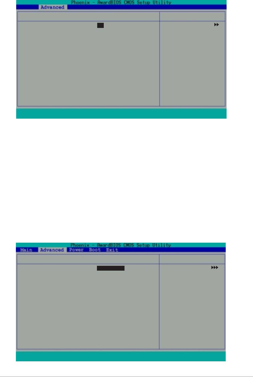
ChipsetChipset
ChipsetChipset
Chipset
The Chipset menu allows you to change the advanced chipset settings.
Select an item then press <Enter> to display the sub-menu.
Chipset
Select Menu
AGP Display switch [Auto]
Item Specific Help
Init Display First [PCI Slot]
AGP Bridge Configuration
F1 : Help
↑
↑↑
↑↑
↓↓
↓
↓↓
: Select Item -/+ : Change Value F5 : Setup Defaults
ESC : Exit
→←→←
→←→←
→←
: Select Menu Enter : Select Sub-menu F10 : Save and Exit
AGP Display switch [Auto]AGP Display switch [Auto]
AGP Display switch [Auto]AGP Display switch [Auto]
AGP Display switch [Auto]
Allows you to set the AGP display control to [Auto] or through the onboard
AGP controller. Configuration options: [Auto] [Onchip AGP]
Init Display First [PCI Slot]
Init Display First [PCI Slot]Init Display First [PCI Slot]
Init Display First [PCI Slot]Init Display First [PCI Slot]
Allows you to select the primary VGA type if your system has multiple
video controllers. Configuration options: [PCI Slot] [AGP]
ASUS A7V400-MX SEASUS A7V400-MX SE
ASUS A7V400-MX SE
ASUS A7V400-MX SEASUS A7V400-MX SE
2-17
2-172-17
2-172-17
AGP Bridge ConfigurationAGP Bridge Configuration
AGP Bridge ConfigurationAGP Bridge Configuration
AGP Bridge Configuration
AGP Bridge Configuration
Select Menu
Graphics Aperture Size [64M]
Item Specific Help
AGP Mode [4X]
AGP Driving Control [Auto]
Select AGP aperture
AGP Driving Value DA
size.
AGP Fast Write [Disabled]
Onboard Video Memory [32M]
F1 : Help
↑↑
↑↑
↑
↓↓
↓
↓↓
: Select Item -/+ : Change Value F5 : Setup Defaults
ESC : Exit
→←→←
→←
→←→←
: Select Menu Enter : Select Sub-menu F10 : Save and Exit
Graphics Aperture Size [64MB]Graphics Aperture Size [64MB]
Graphics Aperture Size [64MB]
Graphics Aperture Size [64MB]Graphics Aperture Size [64MB]
Sets the size of mapped memory for AGP graphic data. Configuration
options: [256M] [128M] [64M] [32M] [16M] [8M] [4M] [1G] [512M]
AGP ModeAGP Mode
AGP Mode
AGP ModeAGP Mode
Sets the AGP transfer mode. AGP 4X transfers video data at 1066 MB/s and
is backward compatible with AGP 1X and 2X AGP cards. When set to [1X],
the AGP interface only provides a peak data throughput of 266 MB/s, even
if you are using an AGP 4X card. Configuration options: [1X] [2X] [4X]
The AGP Mode automatically adjusts to 8X when you install an AGP 8X card.
AGP Driving Control [Auto]AGP Driving Control [Auto]
AGP Driving Control [Auto]AGP Driving Control [Auto]
AGP Driving Control [Auto]
Allows you to automatically select or manually assign the AGP Driving
Value. Configuration options: [Auto] [Manual]
AGP Driving Value [DA]
AGP Driving Value [DA]AGP Driving Value [DA]
AGP Driving Value [DA]AGP Driving Value [DA]
This item is enabled when you set the AGP Driving Control to [Manual].
Press <Enter> to assign a hexadecimal AGP Driving Value. Configuration
options: [Min = 0000, Max = 00FF]
AGP Fast Write [Disabled]AGP Fast Write [Disabled]
AGP Fast Write [Disabled]AGP Fast Write [Disabled]
AGP Fast Write [Disabled]
Enables or disables the AGP Fastwrite function. Configuration options:
[Disable] [Enabled]
Onboard Video Memory [32M]Onboard Video Memory [32M]
Onboard Video Memory [32M]
Onboard Video Memory [32M]Onboard Video Memory [32M]
Allows you to set the share memory size for the onboard VGA.
Configuration options: [16M] [32M] [64M]
2-182-18
2-18
2-182-18
Chapter 2: BIOS setup
Chapter 2: BIOS setupChapter 2: BIOS setup
Chapter 2: BIOS setupChapter 2: BIOS setup
2.5.42.5.4
2.5.42.5.4
2.5.4
PCIPnPPCIPnP
PCIPnPPCIPnP
PCIPnP
The PCIPnP menu allows you to change the settings for installed PCI
devices. Select an item then press <Enter> to display the sub-menu.
PCIPnP
Select Menu
Plug and Play OS [No]
Item Specific Help
Resources Controlled By [Auto]
IRQ Resources
PCI/VGA Palette Snoop [Disabled]
F1 : Help
↑
↑↑
↑↑
↓↓
↓↓
↓
: Select Item -/+ : Change Value F5 : Setup Defaults
ESC : Exit
→←→←
→←→←
→←
: Select Menu Enter : Select Sub-menu F10 : Save and Exit
Plug and Play OS [No]Plug and Play OS [No]
Plug and Play OS [No]Plug and Play OS [No]
Plug and Play OS [No]
When set to [No], BIOS configures all devices in the system. When set to
[Yes], and if you installed a Plug and Play operating system, the operating
system configures the Plug and Play devices not required for boot.
Configuration options: [No] [Yes]
Resources Controlled by [Auto]Resources Controlled by [Auto]
Resources Controlled by [Auto]Resources Controlled by [Auto]
Resources Controlled by [Auto]
When set to [Auto], BIOS automatically configures all Plug and Play
devices. Setting this item to [Manual], allows manual assignment of IRQ
addresses to Plug and Play devices using the IRQ Resources sub-menu
(Refer to the next item). Configuration options: [Auto] [Manual]
IRQ Resources
IRQ ResourcesIRQ Resources
IRQ ResourcesIRQ Resources
IRQ Resources
Select Menu
IRQ-3 assigned to [PCI Device]
Item Specific Help
IRQ-4 assigned to [PCI Device]
IRQ-5 assigned to [PCI Device]
Legacy ISA devices
IRQ-7 assigned to [PCI Device]
compliant with the
IRQ-9 assigned to [PCI Device]
original PC AT bus
IRQ-10 assigned to [PCI Device]
specification, PCI/
IRQ-11 assigned to [PCI Device]
ISA PnP for devices
IRQ-12 assigned to [PCI Device]
compliant with the
IRQ-14 assigned to [PCI Device]
Plug and Play
IRQ-15 assigned to [PCI Device]
standard whether
designed for PCI or
ISA bus architecture.
F1 : Help
↑
↑↑
↑↑
↓
↓↓
↓↓
: Select Item -/+ : Change Value F5 : Setup Defaults
ESC : Exit
→←→←
→←→←
→←
: Select Menu Enter : Select Sub-menu F10 : Save and Exit
ASUS A7V400-MX SEASUS A7V400-MX SE
ASUS A7V400-MX SE
ASUS A7V400-MX SEASUS A7V400-MX SE
2-19
2-192-19
2-192-19
IRQ 3, 4, 5, 7, 9, 10, 11, 12, 14, 15 assigned toIRQ 3, 4, 5, 7, 9, 10, 11, 12, 14, 15 assigned to
IRQ 3, 4, 5, 7, 9, 10, 11, 12, 14, 15 assigned toIRQ 3, 4, 5, 7, 9, 10, 11, 12, 14, 15 assigned to
IRQ 3, 4, 5, 7, 9, 10, 11, 12, 14, 15 assigned to
The IRQ Resources sub-menu is activated when the
Resources
ResourcesResources
ResourcesResources
Controlled by Controlled by
Controlled by Controlled by
Controlled by item is set to [Manual]. Select [PCI Device] to assign an
IRQ address to a Plug and Play device. Setting to [Reserved] reserves the
IRQ address. Configuration options: [PCI Device] [Reserved]
PCI/VGA Palette Snoop [Disabled]PCI/VGA Palette Snoop [Disabled]
PCI/VGA Palette Snoop [Disabled]
PCI/VGA Palette Snoop [Disabled]PCI/VGA Palette Snoop [Disabled]
Some non-standard VGA cards, like graphics accelerators or MPEG video
cards, may not show colors properly. Setting this field to [Enabled] corrects
this problem. If you are using a standard VGA card, leave this field to the
default setting [Disabled]. Configuration options: [Disabled] [Enabled]
2.5.52.5.5
2.5.52.5.5
2.5.5
Onboard Devices Configuration
Onboard Devices ConfigurationOnboard Devices Configuration
Onboard Devices ConfigurationOnboard Devices Configuration
The Onboard Devices Configuration menu allows you to adjust the settings for
onboard devices. Select an item then press <Enter> to display the sub-menu.
Onboard Devices Configuration
Select Menu
OnChip SATA [Enabled]
Item Specific Help
AC97 Audio [Auto]
Onboard LAN [Enabled]
Onboard LAN Boot ROM [Disabled]
Serial Port 1 Address [3F8/IRQ4]
Parallel Port Address [378/IRQ7]
Parallel Port Mode [ECP+EPP]
EPP Mode Select [EPP1.7]
ECP Mode Use DMA [3]
Game Port Address [201]
MIDI Port Address [Disabled]
MIDI Port IRQ 10
F1 : Help
↑↑
↑↑
↑
↓
↓↓
↓↓
: Select Item -/+ : Change Value F5 : Setup Defaults
ESC : Exit
→←→←
→←→←
→←
: Select Menu Enter : Select Sub-menu F10 : Save and Exit
OnChip SATA [Enabled]OnChip SATA [Enabled]
OnChip SATA [Enabled]OnChip SATA [Enabled]
OnChip SATA [Enabled]
Allows you to enable or disable the integrated SATA controller.
Configuration options: [Disabled] [Enabled]
®
Disable the
OnChip SATA OnChip SATA
OnChip SATA item when installing Windows
OnChip SATA OnChip SATA
98/Me
operating system.
AC97 Audio [Auto]AC97 Audio [Auto]
AC97 Audio [Auto]AC97 Audio [Auto]
AC97 Audio [Auto]
This field allows you to enable or disable the onboard AC97 audio
controller. Configuration options: [Auto] [Disabled]
Onboard LAN [Enabled]
Onboard LAN [Enabled]Onboard LAN [Enabled]
Onboard LAN [Enabled]Onboard LAN [Enabled]
This field allows you to enable or disable the onboard LAN controller.
Configuration options: [Enabled] [Disabled]
2-202-20
2-20
2-202-20
Chapter 2: BIOS setup
Chapter 2: BIOS setupChapter 2: BIOS setup
Chapter 2: BIOS setupChapter 2: BIOS setup

Onboard LAN Boot ROM [Disabled]Onboard LAN Boot ROM [Disabled]
Onboard LAN Boot ROM [Disabled]Onboard LAN Boot ROM [Disabled]
Onboard LAN Boot ROM [Disabled]
Allows you to turn on or off the onboard LAN boot ROM. This item appears
only when onboard LAN is enabled. Configuration options: [Enabled]
[Disabled]
Serial Port1 Address [3F8/IRQ4]Serial Port1 Address [3F8/IRQ4]
Serial Port1 Address [3F8/IRQ4]Serial Port1 Address [3F8/IRQ4]
Serial Port1 Address [3F8/IRQ4]
Allows you to set the interrupt address of the serial port.
Configuration options: [Disabled] [3F8/IRQ4] [2F8/1RQ3] [3E8/IRQ4]
[2E8/IRQ3] [Auto]
Parallel Port Address [378/IRQ7]
Parallel Port Address [378/IRQ7]Parallel Port Address [378/IRQ7]
Parallel Port Address [378/IRQ7]Parallel Port Address [378/IRQ7]
Set the address of the onboard parallel port connector.
Configuration options: [Disabled] [378/IRQ7] [278/IRQ5] [3BC/1RQ7]
Parallel Port Mode [ECP+EPP]Parallel Port Mode [ECP+EPP]
Parallel Port Mode [ECP+EPP]Parallel Port Mode [ECP+EPP]
Parallel Port Mode [ECP+EPP]
Sets the parallel port operation mode. Setting to [SPP] allows normal speed
operation but in one direction only. [EPP] allows bi-directional parallel port
operation. [ECP] allows bi-directional DMA mode operation, while [ECP+EPP]
allows normal speed operation in a two-way mode.
Configuration options: [SPP] [EPP] [ECP] [ECP+EPP]
EPP Mode Select [EPP1.7]
EPP Mode Select [EPP1.7]EPP Mode Select [EPP1.7]
EPP Mode Select [EPP1.7]EPP Mode Select [EPP1.7]
This field sets the EPP mode. The default setting is EPP1.7. This selection is
available when you set the Parallel Port Mode to [EPP] or [ECP+EPP].
Configuration options: [EPP1.9] [EPP1.7]
ECP Mode Use DMA [3]
ECP Mode Use DMA [3]ECP Mode Use DMA [3]
ECP Mode Use DMA [3]ECP Mode Use DMA [3]
This field sets the parallel port DMA channel for the selected ECP mode.
The default setting is 3. This selection is available only if you select [ECP]
or [ECP+EPP] in the Parallel Port Mode item. Configuration options: [1] [3]
Game Port Address [201]Game Port Address [201]
Game Port Address [201]
Game Port Address [201]Game Port Address [201]
This field allows you to select the onboard Game port address.
Configuration options: [Disabled] [201] [209]
MIDI Port Address [Disabled]MIDI Port Address [Disabled]
MIDI Port Address [Disabled]MIDI Port Address [Disabled]
MIDI Port Address [Disabled]
This field allows you to select the onboard MIDI port address.
Configuration options: [Disabled] [330] [300] [290]
MIDI Port IRQ [10]
MIDI Port IRQ [10]MIDI Port IRQ [10]
MIDI Port IRQ [10]MIDI Port IRQ [10]
This field allows you to set the IRQ assignment for the onboard MIDI port.
Configuration options: [5] [10]
ASUS A7V400-MX SEASUS A7V400-MX SE
ASUS A7V400-MX SE
ASUS A7V400-MX SEASUS A7V400-MX SE
2-21
2-212-21
2-212-21

2.5.62.5.6
2.5.6
2.5.62.5.6
USB Configuration
USB ConfigurationUSB Configuration
USB ConfigurationUSB Configuration
The USB Configuration menu allows you to adjust the settings for the onboard
USB controllers. Select an item then press <Enter> to display the sub-menu.
USB Configuration
Select Menu
OnChip USB Controller [Enabled]
Item Specific Help
OnChip EHCI Controller [Enabled]
USB Legacy Support [Enabled]
F1 : Help
↑↑
↑↑
↑
↓
↓↓
↓↓
: Select Item -/+ : Change Value F5 : Setup Defaults
ESC : Exit
→←
→←→←
→←→←
: Select Menu Enter : Select Sub-menu F10 : Save and Exit
OnChip USB Controller [Enabled]OnChip USB Controller [Enabled]
OnChip USB Controller [Enabled]OnChip USB Controller [Enabled]
OnChip USB Controller [Enabled]
Allows you to enable or disable the integrated USB controller.
Configuration options: [Enabled] [Disabled]
OnChip EHCI Controller [Enabled]OnChip EHCI Controller [Enabled]
OnChip EHCI Controller [Enabled]OnChip EHCI Controller [Enabled]
OnChip EHCI Controller [Enabled]
Allows you to enable or disable the USB EHCI controller.
Configuration options: [Enabled] [Disabled]
USB Legacy Support [Enabled]USB Legacy Support [Enabled]
USB Legacy Support [Enabled]USB Legacy Support [Enabled]
USB Legacy Support [Enabled]
Allows you to enable or disable support for legacy USB devices.
Configuration options: [Enabled] [Disabled]
2-222-22
2-22
2-222-22
Chapter 2: BIOS setup
Chapter 2: BIOS setupChapter 2: BIOS setup
Chapter 2: BIOS setupChapter 2: BIOS setup

2.6 Power menu
The Power menu items allow you to change the settings for the Advanced
Power Management (APM). Select an item, then press <Enter> to display
the configuration options.
ACPI Suspend Type [S1&S3]
Select Menu
ACPI APIC Support [Enabled]
APM Configuration
Item Specific Help
Hardware Monitor
Select the ACPI stare
used for System
Suspend.
F1 : Help
↑
↑↑
↑↑
↓ : Select Item -/+ : Change Value F5 : Setup Defaults
↓↓
↓↓
ESC : Exit
→←→←
→←: Select Menu Enter : Select Submenu F10: Save and Exit
→←→←
ACPI Suspend Mode [S1&S3]
ACPI Suspend Mode [S1&S3]ACPI Suspend Mode [S1&S3]
ACPI Suspend Mode [S1&S3]ACPI Suspend Mode [S1&S3]
Allows you to select the ACPI state to used for system suspend.
Configuration options: [S1 (POS)] [S3 (STR)] [S1&S3]
ACPI APIC Support [Enabled]ACPI APIC Support [Enabled]
ACPI APIC Support [Enabled]ACPI APIC Support [Enabled]
ACPI APIC Support [Enabled]
Allows you to enable or disable the ACPI support in the ASIC. When set to
[Enabled], the ACPI APIC table pointer is included in the RSDT pointer list.
Configuration options: [Disabled] [Enabled]
ASUS A7V400-MX SEASUS A7V400-MX SE
ASUS A7V400-MX SE
ASUS A7V400-MX SEASUS A7V400-MX SE
2-23
2-232-23
2-232-23
2.6.12.6.1
2.6.12.6.1
2.6.1
APM Configuration
APM ConfigurationAPM Configuration
APM ConfigurationAPM Configuration
APM Configuration
Select Menu
PS2KB Wakeup Select [Hot Key]
Item Specific Help
PS2KB Wakeup Password Clear
PS2KB Wakeup from S3/S4/S5 [Disabled]
Select wakeup by
PS2MS Wakeup from S3/S4/S5 [Disabled]
PS2KB, Hot key, or
USB Resume from S3/S4 [Disabled]
Password.
Power On By PCI Devices [Disabled]
Modem Ring Resume [Disabled]
Power On By RTC Alarm [Disabled]
Date (of Month) 0
Resume Time (hh:mm:ss) 0 : 0 : 0
Video Off Option [Suspend -> Off]
PWR Button < 4 secs [Instant-Off]
Restore on AC Power Loss [Last State]
F1 : Help
↑
↑↑
↑↑
↓
↓↓
↓↓
: Select Item -/+ : Change Value F5 : Setup Defaults
ESC : Exit
→←
→←→←
→←→←
: Select Menu Enter : Select Sub-menu F10 : Save and Exit
PS2KB Wakeup Select [Hot Key]
PS2KB Wakeup Select [Hot Key]PS2KB Wakeup Select [Hot Key]
PS2KB Wakeup Select [Hot Key]PS2KB Wakeup Select [Hot Key]
Allows you to use specific keys on the keyboard to turn on the system.
This feature requires an ATX power supply that provides at least 1 A on
the +5VSB lead. Configuration options: [Hot key] [Password]
PS2KB Wakeup Password [Clear]
PS2KB Wakeup Password [Clear]PS2KB Wakeup Password [Clear]
PS2KB Wakeup Password [Clear]PS2KB Wakeup Password [Clear]
Appears when you select password as the wakeup method for the PS/2
keyboard. Highlight this item then press <Enter> to enter an 8-digit
password. When the password is activated, the system wakes up from a
keyboard stroke only after you enter the correct password. To disable the
password, highlight this item again, then press <Enter> twice. A
PASSWORD DISABLED! message appears indicating that you have
successfully disabled the password.
The PS2KB Wakeup from S3/S4/S5 and thePS2MS Wakeup from S3/S4/
S5 are not configurable if you set the PS2KB Wakeup Select item to
password mode.
PS2KB Wakeup from S3/S4/S5 [Disabled]
PS2KB Wakeup from S3/S4/S5 [Disabled]PS2KB Wakeup from S3/S4/S5 [Disabled]
PS2KB Wakeup from S3/S4/S5 [Disabled]PS2KB Wakeup from S3/S4/S5 [Disabled]
When set to [Enabled], this parameter allows you to use the PS/2
keyboard to turn on the system. Configuration options: [Disabled]
[Ctrl+F1] [Ctrl+F2] [Ctrl+F3] [Ctrl+F4] [Ctrl+F5] [Ctrl+F6] [Ctrl+F7]
[Ctrl+F8] [Ctrl+F9] [Ctrl+F10] [Ctrl+F11] [Ctrl+F12] [Power] [Wake]
[Any Key]
2-242-24
2-24
2-242-24
Chapter 2: BIOS setup
Chapter 2: BIOS setupChapter 2: BIOS setup
Chapter 2: BIOS setupChapter 2: BIOS setup

PS2MS Wakeup from S3/S4/S5 [Disabled]PS2MS Wakeup from S3/S4/S5 [Disabled]
PS2MS Wakeup from S3/S4/S5 [Disabled]PS2MS Wakeup from S3/S4/S5 [Disabled]
PS2MS Wakeup from S3/S4/S5 [Disabled]
When set to [Enabled], this parameter allows you to use the PS/2 mouse
to turn on the system. This requires an ATX power supply that provides at
least 1A on the +5VSB lead. Configuration options: [Disabled] [Enabled]
USB Resume from S3/S4 [Disabled]USB Resume from S3/S4 [Disabled]
USB Resume from S3/S4 [Disabled]USB Resume from S3/S4 [Disabled]
USB Resume from S3/S4 [Disabled]
Configuration options: [Disabled] [Enabled]
Power On By PCI Devices [Disabled]
Power On By PCI Devices [Disabled]Power On By PCI Devices [Disabled]
Power On By PCI Devices [Disabled]Power On By PCI Devices [Disabled]
When set to [Enabled], this parameter allows you to turn on the system
through a PCI LAN or modem card. This feature requires an ATX power
supply that provides at least 1 A on the +5VSB lead.
Configuration options: [Disabled] [Enabled]
Modem Ring Resume [Disabled]Modem Ring Resume [Disabled]
Modem Ring Resume [Disabled]Modem Ring Resume [Disabled]
Modem Ring Resume [Disabled]
When [Enabled] the computer powers up when the external modem
receives a call while the computer is in soft-off mode.
Configuration options: [Disabled] [Enabled]
Power On By RTC Alarm [Disabled]Power On By RTC Alarm [Disabled]
Power On By RTC Alarm [Disabled]
Power On By RTC Alarm [Disabled]Power On By RTC Alarm [Disabled]
Allows you to enable or disable RTC to generate a wake event. When this
item is enabled, the Date and Resume Time fields are activated for manual
setup. Configuration options: [Disabled] [Enabled]
Video Off Option [Suspend -> Off ]
Video Off Option [Suspend -> Off ]Video Off Option [Suspend -> Off ]
Video Off Option [Suspend -> Off ]Video Off Option [Suspend -> Off ]
Determines when to activate the video off feature for monitor power
management. Configuration options: [Always On] [Suspend -> Off]
PWR Button < 4 Sec [Instant-Off]PWR Button < 4 Sec [Instant-Off]
PWR Button < 4 Sec [Instant-Off]PWR Button < 4 Sec [Instant-Off]
PWR Button < 4 Sec [Instant-Off]
When set to [Instant-off], the ATX power button can be used as a normal
system power-off button when pressed for less than 4 seconds. [Suspend]
allows the button to have a dual function where pressing less than 4
seconds puts the system in sleep mode. Regardless of the setting, pressing
the ATX power button for more than 4 seconds powers off the system.
Configuration options: [Suspend] [Instant-off]
Restore on AC Power Loss [Last State]Restore on AC Power Loss [Last State]
Restore on AC Power Loss [Last State]
Restore on AC Power Loss [Last State]Restore on AC Power Loss [Last State]
Allows you to set whether or not to power the system after an AC power
loss. [Off] leaves your system off, while [On] powers up the system.
Setting to [Last State] puts the system back to the state it was before
the AC power interruption. Configuration options: [Last State] [Power On]
[Power Off]
ASUS A7V400-MX SEASUS A7V400-MX SE
ASUS A7V400-MX SE
ASUS A7V400-MX SEASUS A7V400-MX SE
2-25
2-252-25
2-252-25

2.6.22.6.2
2.6.22.6.2
2.6.2
Hardware Monitor
Hardware MonitorHardware Monitor
Hardware MonitorHardware Monitor
Hardware Monitor
Select Menu
Shutdown Temperature [Disabled]
Item Specific Help
System Temperature 33ºC / 91ºF
System will shutdown
CPU Temperature 33ºC / 91ºF
when CPU temperature
is too high.
Chassis Fan Speed 0 RPM
CPU Fan Speed 8881 RPM
Vcore 1.56 V
+ 3.3 V 3.34 V
+ 5 V 4.91 V
+12 V 11.36 V
F1 : Help
↑↑
↑↑
↑
↓↓
↓↓
↓
: Select Item -/+ : Change Value F5 : Setup Defaults
ESC : Exit
→←
→←→←
→←→←
: Select Menu Enter : Select Sub-menu F10 : Save and Exit
Shutdown Temperature [Disabled]Shutdown Temperature [Disabled]
Shutdown Temperature [Disabled]Shutdown Temperature [Disabled]
Shutdown Temperature [Disabled]
Allows BIOS to set a threshold value for the CPU temperature. The system
shuts down when the CPU temperature reaches the threshold value.
Configuration options: [Disabled] [60°C/140°F] [65°C/149°F]
[70°C/158°F] [75°C/167°F]
System Temperature [xxxSystem Temperature [xxx
System Temperature [xxx
System Temperature [xxxSystem Temperature [xxx
°
C/xxxC/xxx
C/xxxC/xxx
C/xxx
°
F]
F]F]
F]F]
CPU Temperature [xxxCPU Temperature [xxx
CPU Temperature [xxx
CPU Temperature [xxxCPU Temperature [xxx
°
C/xxxC/xxx
C/xxx
C/xxxC/xxx
°
F]F]
F]F]
F]
The onboard hardware monitor automatically detects and displays the
system and CPU temperatures.
Chassis Fan Speed [xxxxRPM] or [0RPM]
Chassis Fan Speed [xxxxRPM] or [0RPM]Chassis Fan Speed [xxxxRPM] or [0RPM]
Chassis Fan Speed [xxxxRPM] or [0RPM]Chassis Fan Speed [xxxxRPM] or [0RPM]
CPU Fan Speed [xxxxRPM] or [0RPM]
CPU Fan Speed [xxxxRPM] or [0RPM]CPU Fan Speed [xxxxRPM] or [0RPM]
CPU Fan Speed [xxxxRPM] or [0RPM]CPU Fan Speed [xxxxRPM] or [0RPM]
The onboard hardware monitor automatically detects and displays the CPU
and chassis fan speeds in rotations per minute (RPM). If any of the fans is
not connected to the motherboard, that field shows 0RPM.
Vcore [XX.XX V]Vcore [XX.XX V]
Vcore [XX.XX V]Vcore [XX.XX V]
Vcore [XX.XX V]
+ 3.3V [XX.XX V]+ 3.3V [XX.XX V]
+ 3.3V [XX.XX V]
+ 3.3V [XX.XX V]+ 3.3V [XX.XX V]
+ 5 V [XX.XX V]+ 5 V [XX.XX V]
+ 5 V [XX.XX V]
+ 5 V [XX.XX V]+ 5 V [XX.XX V]
+ 12 V [XX.XX V]+ 12 V [XX.XX V]
+ 12 V [XX.XX V]
+ 12 V [XX.XX V]+ 12 V [XX.XX V]
The onboard hardware monitor automatically detects the voltage output
through the onboard voltage regulators.
2-262-26
2-26
2-262-26
Chapter 2: BIOS setup
Chapter 2: BIOS setupChapter 2: BIOS setup
Chapter 2: BIOS setupChapter 2: BIOS setup
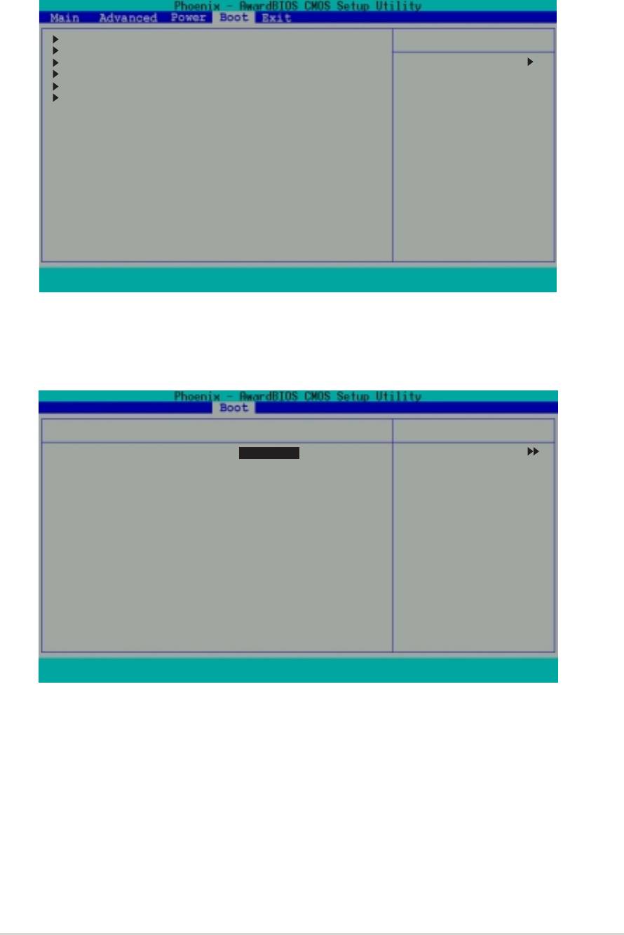
2.7 Boot menu
The Boot menu items allow you to change the system boot settings. Select
a sub-menu, then press <Enter> to display the configuration options.
Boot Device Priority
Select Menu
Removable Drives
Hard Disk Drives
Item Specific Help
CDROM Drives
Boot Settings Configuration
Press [Enter] to set.
Security
F1 : Help
↑
↑↑
↑↑
↓ : Select Item -/+ : Change Value F5 : Setup Defaults
↓↓
↓↓
ESC : Exit
→←→←
→←→←
→←: Select Menu Enter : Select Submenu F10: Save and Exit
2.7.12.7.1
2.7.1
2.7.12.7.1
Boot Device PriorityBoot Device Priority
Boot Device Priority
Boot Device PriorityBoot Device Priority
This menu allows you to arrange the boot device priority.
Boot Device Priority
Select Menu
1st Boot Device [Removable]
Item Specific Help
2nd Boot Device [Hard Disk]
3rd Boot Device [CDROM]
Select your boot
4th Boot Device [Disabled]
device priority.
F1 : Help
↑
↑↑
↑↑
↓↓
↓↓
↓
: Select Item -/+ : Change Value F5 : Setup Defaults
ESC : Exit
→←
→←→←
→←→←
: Select Menu Enter : Select Sub-menu F10 : Save and Exit
1st~4th Boot Device [Removable]1st~4th Boot Device [Removable]
1st~4th Boot Device [Removable]
1st~4th Boot Device [Removable]1st~4th Boot Device [Removable]
Allows you to specify the boot device priority sequence from the available
devices. The number of device items that apear on the screen depends on
the number of devices installed in the system.
Configuration options: [Removable] [Hard Disk] [CDROM] [Legacy LAN]
[Disabled]
ASUS A7V400-MX SEASUS A7V400-MX SE
ASUS A7V400-MX SE
ASUS A7V400-MX SEASUS A7V400-MX SE
2-27
2-272-27
2-272-27
2.7.22.7.2
2.7.22.7.2
2.7.2
Removable Drives
Removable DrivesRemovable Drives
Removable DrivesRemovable Drives
This menu allows you to arrange the removable drive sequence. The screen
shows the removable drive(s) installed in the system. When more than one
removable drives are detected, use the arrow up or down keys to arrange
the devices according to your boot priority.
Removable Drives
Select Menu
1. Floppy Disks
Item Specific Help
Use <
↑> or <
↑↑
↑↑
↓↓
↓↓
↓> to
select a device, then
press <+> to move it
up, or <-> to move it
down the list. Press
<Esc. to exit this
menu.
↑↑
↑
↑↑
↓
↓ ↓
↓ ↓
:Move PU/PD/+/-:Change Priority F10:Save and Exit Esc:Exit without saving
ESC : Exit
→←→←
→←
→←→←
: Select Menu Enter : Select Sub-menu F10 : Save and Exit
2.7.32.7.3
2.7.3
2.7.32.7.3
Hard Disk Drives
Hard Disk DrivesHard Disk Drives
Hard Disk DrivesHard Disk Drives
This menu allows you to arrange the hard disk drive sequence. The screen
shows the hard disk drive(s) installed in the system. When more than one
hard disk drives are detected, use the arrow up or down keys to arrange
the devices according to your boot priority.
Hard Disk Drives
Select Menu
1. 1st Master : XXXXXXXXXXXXXX
Item Specific Help
2. Bootable Add-in Cards
Use <
↑↑
↑> or <
↑↑
↓> to
↓↓
↓↓
select a device, then
press <+> to move it
up, or <-> to move it
down the list. Press
<Esc. to exit this
menu.
↑
↑↑
↑↑
↓
↓ ↓
↓ ↓
:Move PU/PD/+/-:Change Priority F10:Save and Exit Esc:Exit without saving
ESC : Exit
→←→←
→←→←
→←
: Select Menu Enter : Select Sub-menu F10 : Save and Exit
2-28
2-282-28
2-282-28
Chapter 2: BIOS setup
Chapter 2: BIOS setupChapter 2: BIOS setup
Chapter 2: BIOS setupChapter 2: BIOS setup
2.7.42.7.4
2.7.42.7.4
2.7.4
CDROM DrivesCDROM Drives
CDROM DrivesCDROM Drives
CDROM Drives
This menu allows you to arrange the optical drive sequence. The screen
shows the optical drive(s) installed in the system. When more than one
optical drives are detected, use the arrow up or down keys to arrange the
devices according to your boot priority.
CDROM Drives
Select Menu
1. 1st Slave : ASUS CD-S520/A
Item Specific Help
Use <
↑↑
↑↑
↑> or <
↓↓
↓↓
↓> to
select a device, then
press <+> to move it
up, or <-> to move it
down the list. Press
<Esc. to exit this
menu.
↑↑
↑↑
↑
↓ ↓
↓ ↓
↓
:Move PU/PD/+/-:Change Priority F10:Save and Exit Esc:Exit without saving
ESC : Exit
→←
→←→←
→←→←
: Select Menu Enter : Select Sub-menu F10 : Save and Exit
2.7.5
2.7.52.7.5
2.7.52.7.5
Boot Settings ConfigurationBoot Settings Configuration
Boot Settings ConfigurationBoot Settings Configuration
Boot Settings Configuration
This menu allows you to adjust the system boot settings.
Boot Settings Configuration Select Menu
Quick Boot [Enabled]
Item Specific Help
Boot-up Num-Lock [On]
Halt On [All Errors]
Press <Enter> to
enable or disable.
F1 : Help
↑
↑↑
↑↑
↓ : Select Item -/+ : Change Value F5 : Setup Defaults
↓↓
↓↓
ESC : Exit
→←→←
→←→←
→←: Select Menu Enter : Select Submenu F10: Save and Exit
Quick Boot [Enabled]Quick Boot [Enabled]
Quick Boot [Enabled]
Quick Boot [Enabled]Quick Boot [Enabled]
Allows you to enable or disable the system quick boot feature. When
enabled, the system skips certain tests while booting.
Configuration options: [Disabled] [Enabled]
ASUS A7V400-MX SEASUS A7V400-MX SE
ASUS A7V400-MX SE
ASUS A7V400-MX SEASUS A7V400-MX SE
2-29
2-292-29
2-292-29

Bootup Num-lock [On]Bootup Num-lock [On]
Bootup Num-lock [On]Bootup Num-lock [On]
Bootup Num-lock [On]
Allows you to select the power-on state for the keyboard NumLock key.
Configuration options: [Off] [On]
Halt On [All Errors]
Halt On [All Errors]Halt On [All Errors]
Halt On [All Errors]Halt On [All Errors]
Sets the system to halt on errors according to the system functions
specified in each option. Configuration options: [All Errors]
[No Errors] [All, But Keyboard] [All, But Diskette] [All, But Disk/Key]
2.7.62.7.6
2.7.62.7.6
2.7.6
Security
SecuritySecurity
SecuritySecurity
This menu allows you to adjust the system security settings.
Boot Settings Configuration Select Menu
Supervisor Password Clear
Item Specific Help
User Password Clear
Password Check [Setup]
Supervisor password
controls full access.
Press <Enter> to
change password.
F1 : Help
↑↑
↑
↑↑
↓↓
↓↓
↓ : Select Item -/+ : Change Value F5 : Setup Defaults
ESC : Exit
→←→←
→←: Select Menu Enter : Select Submenu F10: Save and Exit
→←→←
Supervisor Password
Supervisor PasswordSupervisor Password
Supervisor PasswordSupervisor Password
User PaswordUser Pasword
User PaswordUser Pasword
User Pasword
Allows you to set the supervisor or user password.
To set a password:
1. Select
Supervisor Password Supervisor Password
Supervisor Password or
Supervisor Password Supervisor Password
User PasswordUser Password
User PasswordUser Password
User Password, then press
<Enter>.
2. Enter the password using a combination of eight (8) alpha-numeric
characters, then press <Enter>.
3. When prompted, re-type the same password, then press <Enter> to
confirm. When the password is activated, the password item value
now shows
Set.
SetSet
SetSet
2-302-30
2-30
2-302-30
Chapter 2: BIOS setup
Chapter 2: BIOS setupChapter 2: BIOS setup
Chapter 2: BIOS setupChapter 2: BIOS setup

To clear the password:
1. Select either the
Supervisor Password or
Supervisor Password Supervisor Password
Supervisor Password Supervisor Password
User PasswordUser Password
User PasswordUser Password
User Password, then
press <Enter> twice. A
Password Disabled! message appears on
Password Disabled! Password Disabled!
Password Disabled! Password Disabled!
screen to indicate that the password has been cleared.
2. Press any key to continue. The password item value now shows
Clear.Clear.
Clear.Clear.
Clear.
A note about passwordsA note about passwords
A note about passwords
A note about passwordsA note about passwords
The BIOS Setup program allows you to specify passwords in the Boot
menu. These passwords control access to the BIOS during system
startup. The BIOS Setup program allows you to specify two different
passwords: a
Supervisor Password and a
Supervisor Password Supervisor Password
Supervisor Password Supervisor Password
User Password. If you
User PasswordUser Password
User PasswordUser Password
did not set a Supervisor Password, anyone can access the BIOS Setup.
If you did, the Supervisor Password is required before entering the BIOS
Setup and gain full access to the configuration fields.
Forgot the password?Forgot the password?
Forgot the password?
Forgot the password?Forgot the password?
If you forget your password, you can clear it by erasing the CMOS Real
Time Clock (RTC) RAM. The RAM data containing the password
information is powered by the onboard button cell battery. If you need
to erase the CMOS RAM, refer to section “1.11 Switch and Jumpers” for
instructions.
Password Check [Setup]Password Check [Setup]
Password Check [Setup]Password Check [Setup]
Password Check [Setup]
Requires users to enter the password before entering the BIOS setup or the
operating system. Select [Setup] to require the password before entering
the BIOS Setup. Select [System] to require the password before entering
the operating system. Configuration options: [Setup] [System]
ASUS A7V400-MX SEASUS A7V400-MX SE
ASUS A7V400-MX SE
ASUS A7V400-MX SEASUS A7V400-MX SE
2-31
2-312-31
2-312-31

2.8 Exit menu
The Exit menu items allow you to save or discard your changes to, and/or
load the optimal or failsafe default values for the BIOS items.
Exit & Save Changes
Select Menu
Exit & Discard Changes
Load Setup Default
Item Specific Help
Discard Changes
This option saves
data to CMOS and
exiting the setup
menu.
F1 : Help
↑↑
↑↑
↑
↓ : Select Item -/+ : Change Value F5 : Setup Defaults
↓↓
↓↓
ESC : Exit
→←→←
→←→←
→←: Select Menu Enter : Select Submenu F10: Save and Exit
Pressing <Esc> does not immediately exit this menu. Select one of the
options from this menu, or press <F10> to exit.
Exit & Save ChangesExit & Save Changes
Exit & Save Changes
Exit & Save ChangesExit & Save Changes
Once you are finished making your selections, choose this option to ensure
the values you selected are saved to the CMOS RAM. An onboard backup
battery sustains the CMOS RAM so it stays on even when the system is
turned off. When you select this option, a confirmation window appears.
Select
Y e s to save changes and exit the BIOS Setup.
YesYes
YesYes
Exit & Discard Changes
Exit & Discard ChangesExit & Discard Changes
Exit & Discard ChangesExit & Discard Changes
Select this option only if you do not want to save the changes that you
made to the BIOS Setup. If you made changes to fields other than the
system date, system time, and password, the BIOS asks for a confirmation
before exiting.
Load Setup DefaultsLoad Setup Defaults
Load Setup DefaultsLoad Setup Defaults
Load Setup Defaults
This option allows you to load the default values for each of the
parameters on the BIOS Setup menus. When you select this option, or if
you press <F5>, a confirmation window appears. Select
YesYes
YesYes
Y e s to load the
default values. Select
Exit & Save Changes or make other changes
Exit & Save ChangesExit & Save Changes
Exit & Save ChangesExit & Save Changes
before saving the values to the non-volatile RAM.
Discard ChangesDiscard Changes
Discard ChangesDiscard Changes
Discard Changes
This option allows you to discard the selections you made and restore the
previously saved values. After selecting this option, a confirmation appears.
Select
YesYes
YesYes
Y e s to discard any changes and load the previously saved values.
2-322-32
2-32
2-322-32
Chapter 2: BIOS setup
Chapter 2: BIOS setupChapter 2: BIOS setup
Chapter 2: BIOS setupChapter 2: BIOS setup
