Asus P5SD2-VM: инструкция
Раздел: Компьютерная техника, комплектующие, аксессуары
Тип: Материнская Плата
Инструкция к Материнской Плате Asus P5SD2-VM

P5SD2-VM
Motherboard

E3464
Revised Edition V2
September 2007
Copyright © 2007 ASUSTeK COMPUTER INC. All Rights Reserved.
No part of this manual, including the products and software described in it, may be reproduced,
transmitted, transcribed, stored in a retrieval system, or translated into any language in any form or by any
means, except documentation kept by the purchaser for backup purposes, without the express written
permission of ASUSTeK COMPUTER INC. (“ASUS”).
Product warranty or service will not be extended if: (1) the product is repaired, modied or altered, unless
such repair, modication of alteration is authorized in writing by ASUS; or (2) the serial number of the
product is defaced or missing.
ASUS PROVIDES THIS MANUAL “AS IS” WITHOUT WARRANTY OF ANY KIND, EITHER EXPRESS
OR IMPLIED, INCLUDING BUT NOT LIMITED TO THE IMPLIED WARRANTIES OR CONDITIONS OF
MERCHANTABILITY OR FITNESS FOR A PARTICULAR PURPOSE. IN NO EVENT SHALL ASUS, ITS
DIRECTORS, OFFICERS, EMPLOYEES OR AGENTS BE LIABLE FOR ANY INDIRECT, SPECIAL,
INCIDENTAL, OR CONSEQUENTIAL DAMAGES (INCLUDING DAMAGES FOR LOSS OF PROFITS,
LOSS OF BUSINESS, LOSS OF USE OR DATA, INTERRUPTION OF BUSINESS AND THE LIKE),
EVEN IF ASUS HAS BEEN ADVISED OF THE POSSIBILITY OF SUCH DAMAGES ARISING FROM ANY
DEFECT OR ERROR IN THIS MANUAL OR PRODUCT.
SPECIFICATIONS AND INFORMATION CONTAINED IN THIS MANUAL ARE FURNISHED FOR
INFORMATIONAL USE ONLY, AND ARE SUBJECT TO CHANGE AT ANY TIME WITHOUT NOTICE,
AND SHOULD NOT BE CONSTRUED AS A COMMITMENT BY ASUS. ASUS ASSUMES NO
RESPONSIBILITY OR LIABILITY FOR ANY ERRORS OR INACCURACIES THAT MAY APPEAR IN THIS
MANUAL, INCLUDING THE PRODUCTS AND SOFTWARE DESCRIBED IN IT.
Products and corporate names appearing in this manual may or may not be registered trademarks or
copyrights of their respective companies, and are used only for identication or explanation and to the
owners’ benet, without intent to infringe.
ii

Contents
Notices ......................................................................................................... vi
Safety information ..................................................................................... vii
P5SD2-VM specications summary ........................................................... x
Chapter 1: Product introduction
1.1 Welcome! ...................................................................................... 1-2
1.2 Package contents .........................................................................
1-2
1.3 Special features ............................................................................
1-2
1.3.1 Product highlights ...........................................................
1-2
1.3.2 ASUS Special features ...................................................
1-4
1.4 Before you proceed .....................................................................
1-5
1.5 Motherboard overview .................................................................
1-6
1.5.1 Placement direction ........................................................
1-6
1.5.2 Screw holes ....................................................................
1-6
1.5.3 Motherboard layout .........................................................
1-7
1.5.4 Layout contents ...............................................................
1-8
1.6 Central Processing Unit (CPU) ...................................................
1-9
1.6.1 Installing the CPU .........................................................
1-10
1.6.2 Installing the CPU heatsink and fan ..............................
1-12
1.6.3 Uninstalling the CPU heatsink and fan .........................
1-14
1.7 System memory .........................................................................
1-16
1.7.1 Overview .......................................................................
1-16
1.7.2 Memory congurations ..................................................
1-16
1.7.3 Installing a DIMM ..........................................................
1-21
1.7.4 Removing a DIMM ........................................................
1-21
1.8 Expansion slots ..........................................................................
1-22
1.8.1 Installing an expansion card .........................................
1-22
1.8.2 Conguring an expansion card .....................................
1-22
1.8.3 Interrupt assignments ...................................................
1-23
1.8.4 PCI slots ........................................................................
1-24
1.8.5 PCI Express x1 slot .......................................................
1-24
1.8.6 PCI Express x16 slot .....................................................
1-24
1.9 Jumpers ......................................................................................
1-25
1.10 Connectors .................................................................................
1-27
1.10.1 Rear panel connectors ..................................................
1-27
1.10.2 Internal connectors .......................................................
1-29
iii

Contents
Chapter 2: BIOS setup
2.1 Managing and updating your BIOS ............................................ 2-2
2.1.1 Creating a bootable oppy disk .......................................
2-2
2.1.2 ASUS EZ Flash utility ......................................................
2-4
2.1.3 AFUDOS utility ................................................................
2-5
2.1.4 ASUS CrashFree BIOS 2 utility ......................................
2-7
2.1.5 ASUS Update utility ........................................................
2-9
2.2 BIOS setup program ..................................................................
2-12
2.2.1 BIOS menu screen ........................................................
2-13
2.2.2 Menu bar .......................................................................
2-13
2.2.3 Navigation keys .............................................................
2-13
2.2.4 Menu items ...................................................................
2-14
2.2.5 Sub-menu items ............................................................
2-14
2.2.6 Conguration elds .......................................................
2-14
2.2.7 Pop-up window .............................................................
2-14
2.2.8 Scroll bar .......................................................................
2-14
2.2.9 General help .................................................................
2-14
2.3 Main menu ..................................................................................
2-15
2.3.1 System Time .................................................................
2-15
2.3.2 System Date .................................................................
2-15
2.3.3 Legacy Diskette A ........................................................
2-15
2.3.4 Primary and SATA IDE Master/Slave ..................................
2-16
2.3.5 IDE Conguration ..........................................................
2-17
2.3.6 System Information .......................................................
2-18
2.4 Advanced menu .........................................................................
2-19
2.4.1 USB Conguration ........................................................
2-19
2.4.2 CPU Conguration ........................................................
2-20
2.4.3 Chipset .........................................................................
2-22
2.4.4 Onboard Devices Conguration ....................................
2-24
2.4.5 PCI PnP ........................................................................
2-25
2.5 Power menu ................................................................................
2-26
2.5.1 Suspend Mode ..............................................................
2-26
2.5.2 Repost Video on S3 Resume ........................................
2-26
2.5.3 ACPI 2.0 Support ..........................................................
2-26
2.5.4 ACPI APIC Support .......................................................
2-26
iv

Contents
2.5.5 APM Conguration ....................................................... 2-27
2.5.6 Hardware Monitor .........................................................
2-28
2.6 Boot menu ..................................................................................
2-29
2.6.1 Boot Device Priority ......................................................
2-29
2.6.2 Boot Settings Conguration ..........................................
2-30
2.6.3 Security .........................................................................
2-31
2.7 Exit menu ....................................................................................
2-33
Chapter 3: Software support
3.1 Installing an operating system ................................................... 3-2
3.2 Support CD information ..............................................................
3-2
3.2.1 Running the support CD .................................................
3-2
3.2.2 Drivers menu ...................................................................
3-3
3.2.3 Utilities menu ..................................................................
3-4
3.2.4 Make Disk menu .............................................................
3-6
3.2.5 Manual menu ..................................................................
3-6
3.2.6 ASUS Contact information ..............................................
3-7
Appendix: CPU features
®
A.1 Enhanced Intel SpeedStep
Technology (EIST) ........................A-2
A.1.1 System requirements ......................................................
A-2
A.1.2 Using the EIST ................................................................
A-2
®
A.2 Intel
Hyper-Threading Technology ...........................................A-4
Using the Hyper-Threading Technology ........................................A-4
v

Notices
Federal Communications Commission Statement
This device complies with Part 15 of the FCC Rules. Operation is subject to the
following two conditions:
•
This device may not cause harmful interference, and
•
This device must accept any interference received including interference that
may cause undesired operation.
This equipment has been tested and found to comply with the limits for a
Class B digital device, pursuant to Part 15 of the FCC Rules. These limits are
designed to provide reasonable protection against harmful interference in a
residential installation. This equipment generates, uses and can radiate radio
frequency energy and, if not installed and used in accordance with manufacturer’s
instructions, may cause harmful interference to radio communications. However,
there is no guarantee that interference will not occur in a particular installation. If
this equipment does cause harmful interference to radio or television reception,
which can be determined by turning the equipment off and on, the user is
encouraged to try to correct the interference by one or more of the following
measures:
•
Reorient or relocate the receiving antenna.
•
Increase the separation between the equipment and receiver.
•
Connect the equipment to an outlet on a circuit different from that to which the
receiver is connected.
•
Consult the dealer or an experienced radio/TV technician for help.
The use of shielded cables for connection of the monitor to the graphics card is
required to assure compliance with FCC regulations. Changes or modications
to this unit not expressly approved by the party responsible for compliance
could void the user’s authority to operate this equipment.
Canadian Department of Communications Statement
This digital apparatus does not exceed the Class B limits for radio noise emissions
from digital apparatus set out in the Radio Interference Regulations of the
Canadian Department of Communications.
This class B digital apparatus complies with Canadian ICES-003.
vi
Safety information
Electrical safety
•
To prevent electrical shock hazard, disconnect the power cable from the
electrical outlet before relocating the system.
•
When adding or removing devices to or from the system, ensure that the
power cables for the devices are unplugged before the signal cables are
connected. If possible, disconnect all power cables from the existing system
before you add a device.
•
Before connecting or removing signal cables from the motherboard, ensure
that all power cables are unplugged.
•
Seek professional assistance before using an adpater or extension cord.
These devices could interrupt the grounding circuit.
•
Make sure that your power supply is set to the correct voltage in your area.
If you are not sure about the voltage of the electrical outlet you are using,
contact your local power company.
•
If the power supply is broken, do not try to x it by yourself. Contact a
qualied service technician or your retailer.
Operation safety
•
Before installing the motherboard and adding devices on it, carefully read all
the manuals that came with the package.
•
Before using the product, make sure all cables are correctly connected and the
power cables are not damaged. If you detect any damage, contact your dealer
immediately.
•
To avoid short circuits, keep paper clips, screws, and staples away from
connectors, slots, sockets and circuitry.
•
Avoid dust, humidity, and temperature extremes. Do not place the product in
any area where it may become wet.
•
Place the product on a stable surface.
•
If you encounter technical problems with the product, contact a qualied
service technician or your retailer.
The symbol of the crossed out wheeled bin indicates that the product (electrical
and electronic equipment, Mercury-containing button cell battery) should not
be placed in municipal waste. Please check local regulations for disposal of
electronic products.
vii

About this guide
This user guide contains the information you need when installing and conguring
the motherboard.
How this guide is organized
This manual contains the following parts:
• Chapter 1: Product introduction
This chapter describes the features of the motherboard and the new
technology it supports. It also lists the hardware setup procedures that you
have to perform when installing system components. It includes description of
the jumpers and connectors on the motherboard.
• Chapter 2: BIOS setup
This chapter tells how to change system settings through the BIOS Setup
menus. Detailed descriptions of the BIOS parameters are also provided.
• Chapter 3: Software support
This chapter describes the contents of the support CD that comes with the
motherboard package.
• Appendix: CPU features
The appendix describes the CPU features this motherboard supports.
Where to nd more information
Refer to the following sources for additional information and for product and
software updates.
1. ASUS websites
The ASUS website provides updated information on ASUS hardware and
software products. Refer to the ASUS contact information.
2. Optional documentation
Your product package may include optional documentation, such as warranty
yers, that may have been added by your dealer. These documents are not
part of the standard package.
viii

Conventions used in this guide
To make sure that you perform certain tasks properly, take note of the following
symbols used throughout this manual.
DANGER/WARNING: Information to prevent injury to yourself
when trying to complete a task.
CAUTION: Information to prevent damage to the components
when trying to complete a task.
IMPORTANT: Instructions that you MUST follow to complete a
task.
NOTE: Tips and additional information to help you complete a
task.
Typography
Bold text Indicates a menu or an item to select.
Italics
Used to emphasize a word or a phrase.
<Key> Keys enclosed in the less-than and greater-than sign
means that you must press the enclosed key.
Example: <Enter> means that you must press the
Enter or Return key.
<Key1>+<Key2>+<Key3> If you must press two or more keys simultaneously, the
key names are linked with a plus sign (+).
Example: <Ctrl>+<Alt>+<D>
Command Means that you must type the command exactly
as shown, then supply the required item or value
enclosed in brackets.
Example: At the DOS prompt, type the command line:
afudos /i[lename]
afudos /iP5SD2VM.ROM
ix
P5SD2-VM specications summary
®
CPU LGA775 socket for Intel
Core™2 Duo/
®
®
®
Pentium
D / Pentium
4 / Celeron
D Processors
®
Support Intel
next generation 45nm CPU
®
Compatible with Intel
05B/05A/06 processors
®
Intel
EIST Hyper-Threading Technology ready
(Refer to www.asus.com for Intel CPU support list)
Chipset Northbridge: SIS 672
Southbridge: SIS 968
System Bus 1066 o.c / 800 / 533 MHz
Memory 2 x 240-pin DIMM sockets supports unbuffered non-ECC
4GB 667/533 MHz DDR2 memory modules
Expansion Slots 1 x PCI Express x 16 slot
1 x PCI Express x 1 slot
2 x PCI slots
VGA SIS Mirage 3+ Integrated Graphics, up to 256MB shared
memory
Storage Southbridge SIS968 supports:
- 1 x UltraDMA 133/100/66/33 hard disk drives
- 2 x SATA 3Gb/s with RAID 0, 1 function
LAN PHY 10/100 LAN
®
Audio Realtek
ALC 662 6-channel High Denition Audio
CODEC
Support Jack-detect and SPIDF-OUT interface
USB 8 x USB2.0 ports
ASUS Features ASUS CrashFree BIOS 2
ASUS EZ Flash
ASUS Q-Fan
ASUS MyLogo
Rear panel 1 x PS/2 keyboard port
1 x PS/2 mouse port
1 x Parallel port
1 x VGA port
1 x COM port
1 x LAN (RJ-45) port
4 x USB 2.0/1.1 ports
6-channel audio I/O port
(continued on the next page)
x
P5SD2-VM specications summary
Internal connectors 2 x USB 2.0 connectors support additional 4 USB 2.0 ports
1 x CPU / 1 x Chassis fan connectors
1 x S/PDIF Out connector
1 x Chassis intrusion connector
1 x Front panel audio connector
1 x CD audio-in connector
1 x 24-pin ATX power connector
1 x 4-pin ATX 12 V power connector
1 x 4-pin internal speaker connector
1 x Floppy disk connector
1 x System panel connector
1 x IDE connector for two devices
Support CD contents Drivers
ASUS PC Probe 2
ASUS LiveUpdate Utility
Anti-virus software (OEM version)
Other Accessories 1 x SATA cable
1 x SATA power cable
1 x UltraDMA 133/100/66 cable
1 x FDD cable
1 x I/O Shield
User manual
Form factor Micro-ATX form factor: 9.6’ in x 7.4’ in
(24.4 cm x 18.8 cm)
*Specications are subject to change without notice.
xi

xii
This chapter describes the motherboard
features and the new technologies
it supports.
Product
1
introduction
1.1 Welcome!
®
Thank you for buying an ASUS
P5SD2-VM motherboard!
The motherboard delivers a host of new features and latest technologies, making it
another standout in the long line of ASUS quality motherboards!
Before you start installing the motherboard, and hardware devices on it, check the
items in your package with the list below.
1.2 Package contents
Check your motherboard package for the following items.
Motherboard ASUS P5SD2-VM
Cables 1 x Ultra DMA 133/100/66 cable
1 x SATA cable
1 x SATA power cable
1 x Floppy disk drive cable
Accessories I/O shield
Application CD ASUS motherboard support CD
Documentation User guide
If any of the above items is damaged or missing, contact your retailer.
1.3 Special features
1.3.1 Product highlights
Intel® Core™2 Processor Ready
®
This motherboard supports Intel
Core™2 processor in the LGA775 package. With
®
Intel
Core™ microarchitecture technology and 1066 o.c / 800/ 533MHz FSB, Intel
®
Core™2 processor is one of the most powerful and energy efcient CPU in the
world.
Intel LGA775 CPU
This motherboard supports the latest Pentium 4 CPU from Intel in LGA775
package. With 1066 o.c/ 800/ 533MHz FSB, Hyper-Threading Technology and
core-speeds up to 3.8GHz and beyond.
1-2 Chapter 1: Product introduction

Intel® 65nm Dual-Core CPU support
This motherboard supports Intel® Pentium® D/Pentium® 4/Celeron® dual-
core processors built on the 65-nanometer (nm) process technology with copper
interconnect. Dual-core processors contain two physical CPU cores with dedicated
L2 caches to meet demands for more powerful processing. Intel®’s 65nm process
delivers breakthrough performance, enhanced media experience, and low
power consumption. Intel® 65nm dual-core processors utilize the latest package
technologies for a thinner, lighter design without compromising performance.
64-bit CPU support
The motherboard supports 64-bit processors that provides high performance
computing and faster memory access required for memory and data intensive
applications.
Universal PCI-E Slot
The Universal PCI Express technology offers utilization exibility of the Southbridge
PCI Express interface. It enables users to plug in an additional PCI Express
graphics card to set up a dual graphics card platform on a single motherboard.
ASUS’ own smart quick switch further detects how users installed their PCI
Express devices, and intelligently reroutes the PCI Express lanes for optimized
bandwidth allocation.
Serial ATA 3Gb/s technology
This motherboard supports the next-generation hard drives based on the Serial
ATA (SATA) 3Gb/s storage specification, delivering enhanced scalability and
doubling the bus bandwidth for high-speed data retrieval and saves. Easily backup
photos, videos and other entertainment contents to external devices. See page
1-31 for details.
S/PDIF digital sound ready
The motherboard supports the S/PDIF-out (SONY-PHILIPS Digtal Interface)
function through the S/PDIF interface at mid-board. It allows to transfer digital
audio without converting to analog format and keeps the best signal quality. See
page 1-29 for details.
ASUS P5SD2-VM 1-3

High Denition Audio
Enjoy high-end sound quality on your PC! The onboard 6-channel HD audio (High
Definition Audio, previously codenamed Azalia) CODEC enables high-quality
192KHz/24-bit audio output, jack-sensing feature.
SIS Advanced HyperStreaming™ Architecture
The motherboard supports the SIS HyperStreaming™ technology that smartly
manages data streaming between the Northbridge and Southbridge, memory,
graphics interface, and other peripherals for efcient and superior performance.
PCI Express™ interface
The motherboard fully supports PCI Express, the latest I/O interconnect
technology that speeds up the PCI bus. PCI Express features point-to-point serial
interconnections between devices and allows higher clockspeeds by carrying data
in packets. This high speed interface is software compatible with existing PCI
specications.
1.3.2 ASUS Special features
ASUS Q-Fan technology
The ASUS Q-Fan technology smartly adjusts the fan speeds according
to the sy ste m loa din g to e nsu re q uie t, co ol, an d e ffic ien t o per ati on.
See page 2-28 for details.
ASUS MyLogo™
This new feature present in the motherboard allows you to personalize and add
style to your system with customizable boot logos.
ASUS EZ Flash
With the ASUS EZ Flash, you can easily update the system BIOS even before
loading the operating system. No need to use a DOS-based utility or boot from a
oppy disk. See page 2-4 for details.
ASUS CrashFree BIOS 2
This feature allows you to restore the original BIOS data from the support CD in
case when the BIOS codes and data are corrupted. This protection eliminates the
need to buy a replacement ROM chip. See page 2-7 for details.
1-4 Chapter 1: Product introduction
1.4 Before you proceed
Take note of the following precautions before you install motherboard components
or change any motherboard settings.
• Unplug the power cord from the wall socket before touching any
component.
• Use a grounded wrist strap or touch a safely grounded object or
a metal object, such as the power supply case, before handling
components to avoid damaging them due to static electricity.
• Hold components by the edges to avoid touching the ICs on them.
• Whenever you uninstall any component, place it on a grounded
antistatic pad or in the bag that came with the component.
• Before you install or remove any component, ensure
that the ATX power supply is switched off or the power cord is detached
from the power supply. Failure to do so may cause severe damage to the
motherboard, peripherals, and/or components.
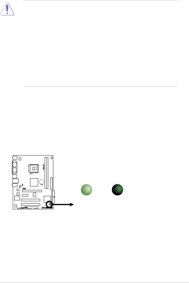
Onboard LED
The motherboard comes with a standby power LED that lights up to indicate
that the system is ON, in sleep mode, or in soft-off mode. This is a reminder
that you should shut down the system and unplug the power cable before
removing or plugging in any motherboard component. The illustration below
shows the location of the onboard LED.
ASUS P5SD2-VM 1-5
SB_PWR
P5 SD 2- VM
ON
OFF
Standby
Powered
Power
Off
P5SD2-VM
Onboard LED
1-6 Chapter 1: Product introduction
P5SD2-VM
1.5 Motherboard overview
Before you install the motherboard, study the conguration of your chassis to
ensure that the motherboard ts into it.
Make sure to unplug the power cord before installing or removing the
motherboard. Failure to do so can cause you physical injury and damage
motherboard components.
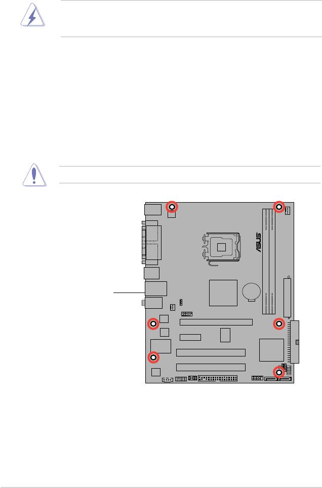
1.5.1 Placement direction
When installing the motherboard, make sure that you place it into the chassis in the
correct orientation. The edge with external ports goes to the rear part of the chassis
as indicated in the image below.
1.5.2 Screw holes
Place six (6) screws into the holes indicated by circles to secure the motherboard
to the chassis.
Do not overtighten the screws! Doing so can damage the motherboard.
Place this side towards
the rear of the chassis
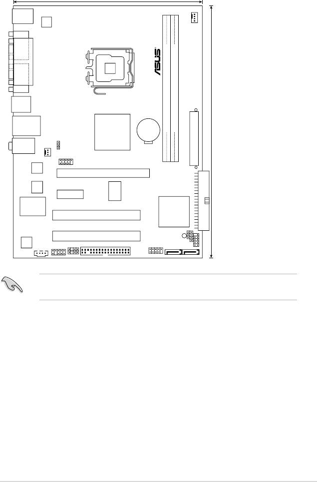
1.5.3 Motherboard layout
Refer to section 1.10 Connectors for more information about rear panel
connectors and internal connectors.
ASUS P5SD2-VM 1-7
SIS 672
SIS 968
1
8.3cm
(
7.2in
)
18.8cm(7.4in)
PS/2KBMS
T: Mouse
B: Keyboard
CPU_FAN
ATX12V
COM1
LGA775
PARALLEL PORT
VGA1
(64 bit,240-pin module)
2
USB34
LAN1_USB12
CR2032 3V
Lithium Cell
CMOS Power
DDR2 DIMM1 (64 bit,240-pin module)
DDR2 DIMM
24.4cm(9.6in)
AUDIO
PS2_USB_PWR
EATXPWR
CHA_FAN
USB78
Atheros
F2
PCIEX16
4Mb
BIOS
PCIEX1_1
RTM876-660
Super I/O
P5SD2-VM
PCI1
SPEAKER
PRI_IDE
PCI2
SB_PWR
ALC662
CHASSIS
SPDIF_OUT
FLOPPY
CD
AAFP
USB56
SATA2
CLRTC
F_PANEL
SATA1

1.5.4 Layout contents
Slots Page
1. DDR2 DIMM slots 1-16
2. PCI slots 1-24
3. PCI Express x1 slot 1-24
4. PCI Express x16 slot 1-24
Jumper Page
1. Clear RTC RAM (3-pin CLRTC) 1-25
2. USB device wake-up (3-pin USBPW1-4, USBPW56, PS2-USBPW) 1-26
Rear panel connectors Page
1. PS/2 mouse port (green)
1-27
2. Parallel port
1-27
3.
LAN (RJ-45) port 1-27
4.
Line In port (light blue) 1-27
5.
Line Out port (lime) 1-27
6.
Microphone port (pink) 1-27
7.
USB 2.0 ports 1 and 2 1-28
8.
USB 2.0 ports 3 and 4 1-28
9.
VGA port 1-28
10. Serial port 1-28
11. PS/2 keyboard port (purple) 1-28
Internal connectors Pag
e
1. Floppy disk drive connector (34-1 pin FLOPPY) 1-29
2. Digital Audio connector (4-1 pin SPDIF_OUT) 1-29
3. IDE connector (40-1 pin PRI_IDE) 1-30
4. Serial ATA connectors (7-pin SATA1, SATA2) 1-31
5. USB connectors (10-1 pin USB56 78) 1-31
6. Optical drive audio connector (4-pin CD) 1-32
7. CPU and chassis fan connectors (4-pin CPU_FAN, 1-32
3-pin CHA_FAN)
8. Chassis intrusion connector (4-1 pin CHASSIS) 1-33
9. Front panel audio connector (10-1 pin AAFP) 1-33
10. ATX power connectors (24-pin EATXPWR, 4-pin ATX 12V) 1-34
11. System panel connector (10-1 pin PANEL) 1-35
1-8 Chapter 1: Product introduction
1.6 Central Processing Unit (CPU)
The motherboard comes with a surface mount LGA775 socket designed for the
®
®
®
®
Intel
Core™2 Duo/Pentium
D/Pentium
4 and Celeron
processors.
•
Make sure the AC power is off before you install the CPU.
• If installing a dual-core CPU, connect the chassis fan cable to the chassis
fan connector to ensure system stability.
•
Upon purchase of the motherboard, make sure that the PnP cap is on
the socket and the socket contacts are not bent. Contact your retailer
immediately if the PnP cap is missing, or if you see any damage to the PnP
cap/socket contacts/motherboard components. ASUS will shoulder the cost
of repair only if the damage is shipment/transit-related.
•
Keep the cap after installing the motherboard. ASUS will process Return
Merchandise Authorization (RMA) requests only if the motherboard comes
with the cap on the LGA775 socket.
• The product warranty does not cover damage to the socket contacts
resulting from incorrect CPU installation/removal, or misplacement/loss/
incorrect removal of the PnP cap.
ASUS P5SD2-VM 1-9
1.6.1 Installing the CPU
To install a CPU:
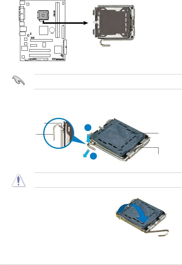
1. Locate the CPU socket on the motherboard.
Before installing the CPU, make sure that the cam box is facing towards you
and the load lever is on your left.
2. Press the load lever with your thumb (A), then move it to the left (B) until it is
released from the retention tab.
Retention tab
A
PnP cap
Load lever
B
This side of the socket box
should face you.
To prevent damage to the socket pins, do not remove the PnP cap unless you
are installing a CPU.
3. Lift the load lever in the direction of
the arrow to a 135º angle.
1-10 Chapter 1: Product introduction
P5 SD2 -VM
P5SD2-VM CPU Socket 775
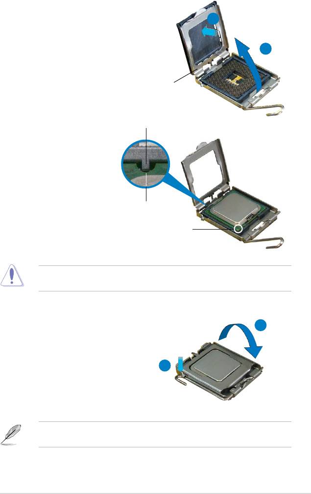
4. Lift the load plate with your thumb
and forenger to a 100º angle (A),
B
then push the PnP cap from the load
plate window to remove (B).
A
Load plate
Alignment key
5. Position the CPU over the
socket, making sure that
the gold triangle is on the
bottom-left corner of the
socket then t the socket
alignment key into the
CPU notch
CPU notch.
Gold triangle mark
The CPU ts in only one correct orientation. DO NOT force the CPU into the
socket to prevent bending the connectors on the socket and damaging the CPU!
A
6. Close the load plate (A), then
push the load lever (B) until it
snaps into the retention tab.
7. If installing a dual-core CPU,
B
connect the chassis fan cable
to the chassis fan connector to
ensure system stability.
®
The motherboard supports Intel
LGA775 processors with Hyper-Threading
Technology. Refer to the Appendix for more information on these CPU features.
ASUS P5SD2-VM 1-11
1.6.2 Installing the CPU heatsink and fan
®
The Intel
LGA775 processor requires a specially designed heatsink and fan
assembly to ensure optimum thermal condition and performance.
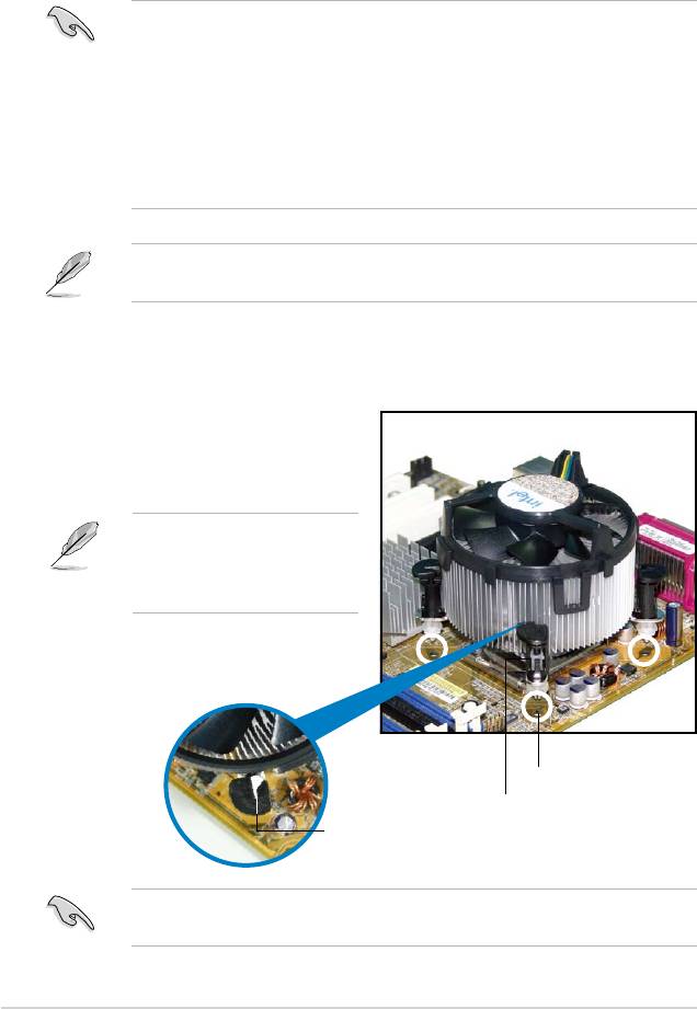
®
•
When you buy a boxed Intel
processor, the package includes the CPU fan
and heatsink assembly. If you buy a CPU separately, make sure that you
®
use only Intel
-certied multi-directional heatsink and fan.
®
•
Your Intel
LGA775 heatsink and fan assembly comes in a push-pin design
and requires no tool to install.
•
If you purchased a separate CPU heatsink and fan assembly, make sure
that you have properly applied Thermal Interface Material to the CPU
heatsink or CPU before you install the heatsink and fan assembly.
Make sure that you have installed the motherboard to the chassis before you
install the CPU fan and heatsink assembly.
To install the CPU heatsink and fan:
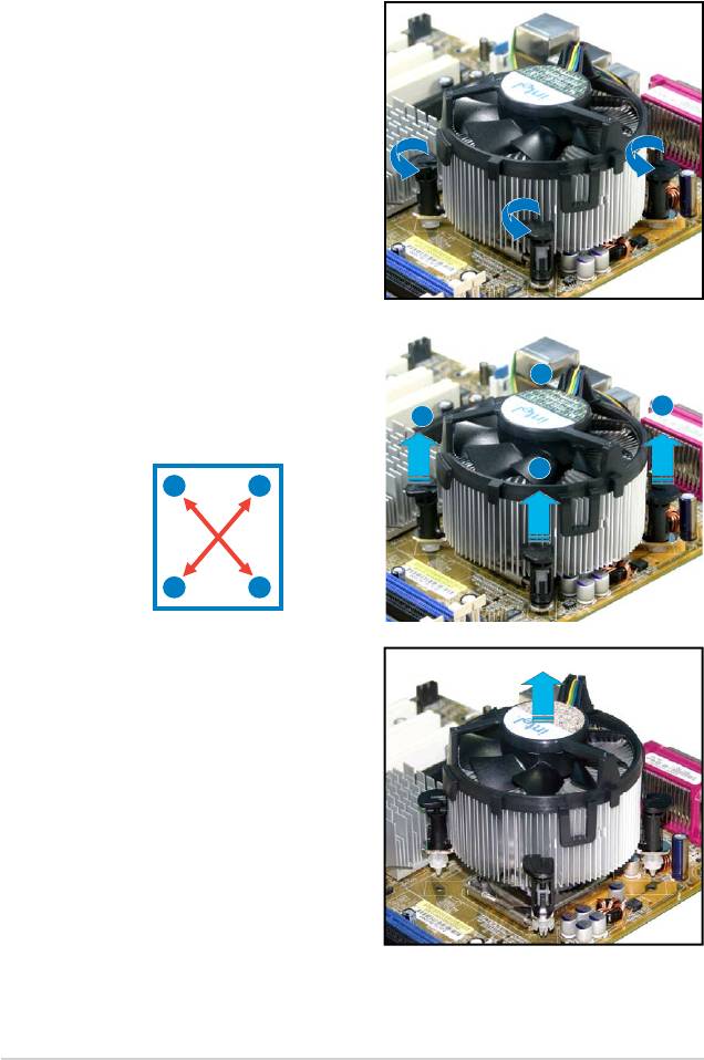
1. Place the heatsink on top of the
installed CPU, making sure that
the four fasteners match the holes
on the motherboard.
Orient the heatsink and fan
assembly such that the CPU
fan cable is closest to the CPU
fan connector.
Motherboard hole
Fastener
Narrow end
of the groove
Make sure to orient each fastener with the narrow end of the groove pointing
outward. (The photo shows the groove shaded for emphasis.)
1-12 Chapter 1: Product introduction
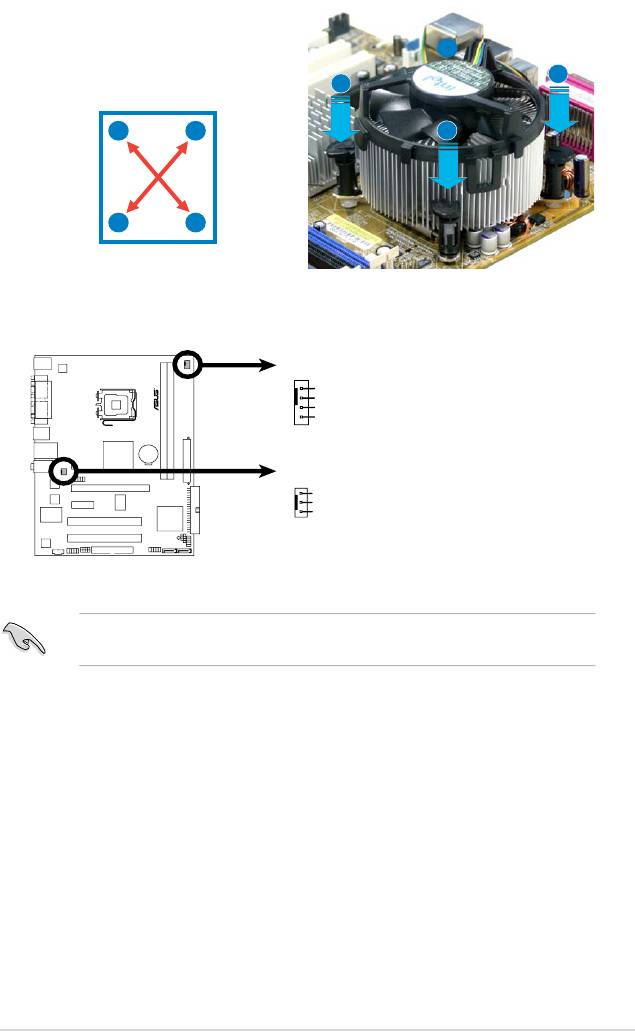
2. Push down two fasteners at a time in
a diagonal sequence to secure the
B
heatsink and fan assembly in place.
A
A
A
B
B
B
A
3. Connect the CPU fan cable to the connector on the motherboard labeled
CPU_FAN.
Do not forget to connect the CPU fan connector! Hardware monitoring errors
can occur if you fail to plug this connector.
ASUS P5SD2-VM 1-13
CPU_FAN
GND
CPU FAN PWR
CPU FAN IN
CPU FAN PW
P5 SD2 -V M
P5SD2-VM
Fan Connectors
M
CHA_FAN
GND
+12V
Rotation
1.6.3 Uninstalling the CPU heatsink and fan
To uninstall the CPU heatsink and fan:
1. Disconnect the CPU fan cable from
the connector on the motherboard.
2. Rotate each fastener
counterclockwise.
3. Pull up two fasteners at a time in
a diagonal sequence to disengage
B
the heatsink and fan assembly
from the motherboard.
A
A
B
A
B
B
A
4. Carefully remove the heatsink
and fan assembly from the
motherboard.
1-14 Chapter 1: Product introduction
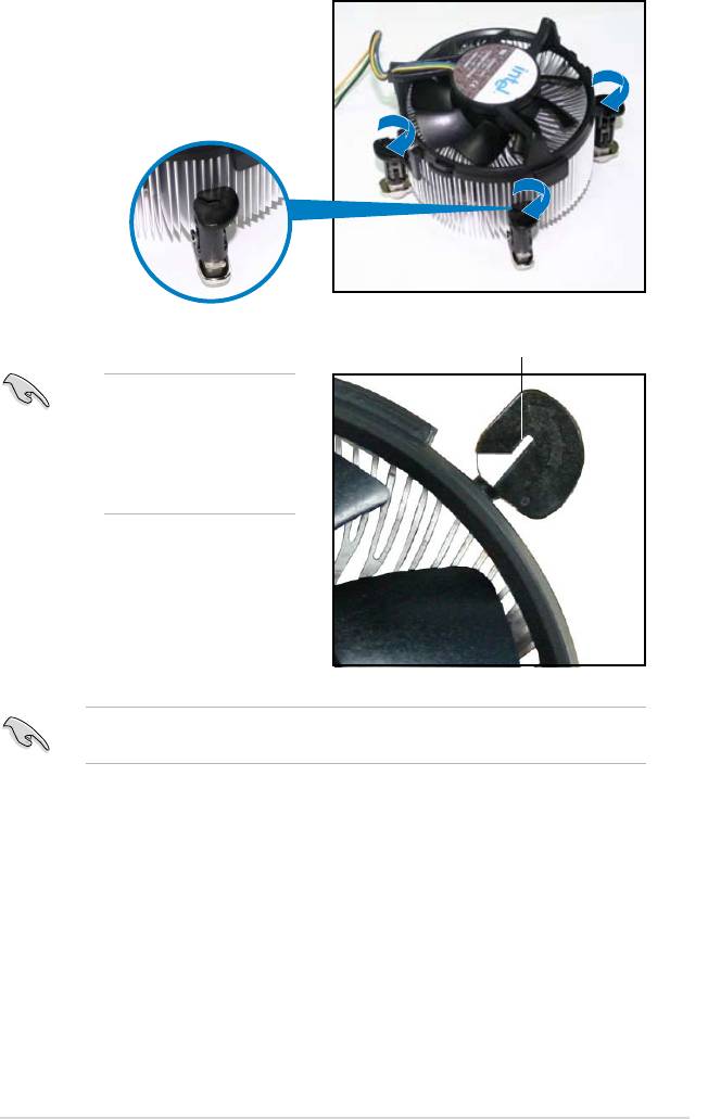
5. Rotate each fastener clockwise to
ensure correct orientation when
reinstalling.
Narrow end of the groove
The narrow end of the
groove should point
outward after resetting.
(The photo shows the
groove shaded for
emphasis.)
Refer to the documentation in the boxed or stand-alone CPU fan package for
detailed information on CPU fan installation.
ASUS P5SD2-VM 1-15
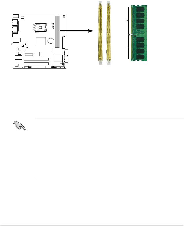
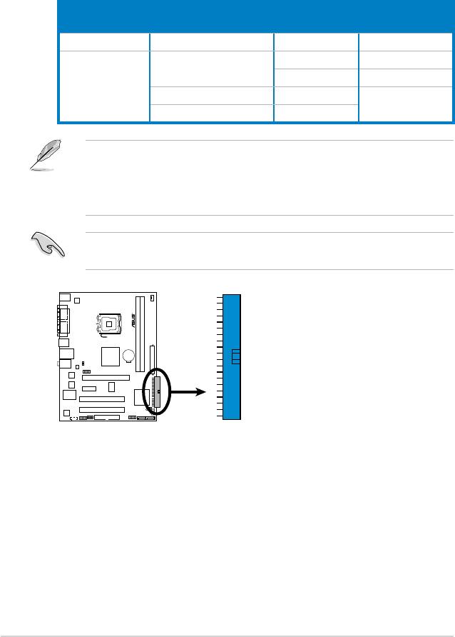
1.7 System memory
1.7.1 Overview
The motherboard comes with two Double Data Rate 2 (DDR2) Dual Inline Memory
Modules (DIMM) sockets.
A DDR2 module has the same physical dimensions as a DDR DIMM but has a
240-pin footprint compared to the 184-pin DDR DIMM. DDR2 DIMMs are notched
differently to prevent installation on a DDR DIMM socket.
The gure illustrates the location of the DDR2 DIMM sockets:
1.7.2 Memory congurations
You may install 512 MB, 1 GB and 2 GB unbuffered non-ECC DDR2 DIMMs into
the DIMM sockets.
1-16 Chapter 1: Product introduction
DIMM1
DIMM2
128 Pins
112 Pins
P5 SD 2-V M
P5SD2-VM
240-pin DDR2 DIMM Sockets
• Always install DIMMs with the same CAS latency. For optimum compatibility,
it is recommended that you obtain memory modules from the same vendor.
• I f y o u ins t all t wo 2 G B m emory m o d ules , t h e s y stem ma y o n ly
recognize less than 3GB because the address space is reserved for
®
other critical functions. This limitation appears on Windows
XP 32-bit
operation system which does not support Physical Address Extension (PAE).
®
• If you install Windows
XP 32-bit operation system, a total memory of less
than 3GB is recommended.
Notes on memory limitations
• Due to chipset limitation, this motherboard can only support up to
4 GB on the operating systems listed below. You may install a maximum of
2 GB DIMMs on each slot, but only DDR2-533 and DDR2-667 2 GB density
modules are available for this conguration.
32-bit 64-bit
®
®
Windows
XP Windows
XP x64 Edition
®
®
Windows
2003 server Windows
2003 server x64 Edition
®
• Some old-version DDR2-667 DIMMs may not match Intel
’s
On-Die-Termination (ODT) requirement and will automatically downgrade
to run at DDR2-533. If this happens, contact your memory vendor to check
the ODT value.
• Due to chipset limitation, DDR2-667 with CL=3 will be downgraded to run
at DDR2-533 by default setting. If you want to operate with lower latency,
adjust the memory timing manually. There will be 4MB reduction in total
memory when enabling ASUS Thermostat function under Single Channel
mode.
ASUS P5SD2-VM 1-17
Qualied Vendors Lists (QVL)
DIMM support
DDR2 667
DIMM support
Size Vendor Model Brand Side(s) Part No. DIMM1 DIMM2
256MB Kingston KVR667D2N5/256 Elpida SS E2508AB-6E-E • •
256MB Kingston KVR667D2N5/256 Kingston SS D3216TLSAKL3U • •
256MB Kingston KVR667D2N5/256 Inneon SS HYB18T256800AF3SW65 33154 • •
512MB Kingston KVR667D2N5/512 Kingston SS D6408TE8WL-27 • •
512MB Kingston KVR667D2N5/512 Elpida SS E5108AGBG-6E-E • •
1G Kingston KVR667D2N5/1G Kingston DS D6408TE8WL-3 • •
1G Kingston KVR667D2N5/1G Kingston DS D6408TEBGGL3U • •
1G Kingston KVR667D2N5/1G Elpida DS E5108AGBG-6E-E • •
512MB Samsung KR M378T6553CZ0-CE6 Samsung SS K4T51083QC • •
512MB Samsung KR M378T6453FZ0-CE6 Samsung DS K4T56083QF-ZCE6 • •
512MB Samsung M378T6553CZ3-CE6 Samsung SS K4T51083QC-ZCE6 • •
1G Samsung M378T2953CZ3-CE6 Samsung DS K4T51083QC-ZCE6 • •
1G Samsung KR M378T2953CZ0-CE6 Samsung DS K4T51083QC-ZCE6 • •
256MB Qimonda HYS64T32000HU-3S-A Qimonda SS HYB18T512160AF-3SSSS17310 • •
512MB Qimonda HYS64T32000HU-3S-A Qimonda SS HYB18T5128000AF-3SSSS27416 • •
512MB Qimonda HYS64T64000HU-3S-A Qimonda SS HYB18T512800AF3SFSS05346 • •
1G Qimonda HYS64T128020HU-3S-A Qimonda DS HYB18T512800AF3SSSS28104 • •
512MB Corsair VS512MB667D2 Corsair SS 64M8CFEGPS0900647 • •
512MB Corsair VS512MB667D2 Corsair DS MIII0052532M8CEC • •
1G Corsair VS1GB667D2 Corsair DS MID095D62864M8CEC • •
1G Corsair XMS2-5400 Corsair DS Heat-Sink Package • •
256MB HY HYMP532U64CP6-Y5 AB Hynix SS HY5PS121621CFP-Y5 • •
512MB HY HYMP564U64AP8-Y4 AA Hynix SS HY5PS12821AFP-Y4 • •
512MB HY HYMP564U64AP8-Y5 AA Hynix SS HY5PS12821AFP-Y5 • •
1G HY HYMP512U64AP8-Y5 AB Hynix DS HY5PS12821AFP-Y5 • •
1G HY HYMP512U64CP8-Y5 AB Hynix DS HY5PS12521CFP-Y5 • •
512MB Kingmax KLCC28F-A8EB5 Elpida SS E5108AE-6E-E • •
512MB Kingmax KLCC28F-A8KB5 Kingmax SS KKEA88B4LAUG-29DX • •
1G Kingmax KLCD48F-A8KB5 Kingmax DS KKEA88B4LAUG-29DX • •
512MB Apacer 78.91092.420 Elpida SS E5108AE-6E-E • •
512MB Apacer AU512E667C5KBGC Apacer SS AM4B5708MIJS7E0627B • •
512MB Apacer AU512E667C5KBGC Apacer SS AM4B5708GQJS7E06332F • •
1G Apacer AU01GE667C5KBGC Apacer DS AM4B5708GQJS7E0636B • •
1G Apacer 78.01092.420 Elpida DS E5108AE-6E-E • •
1G Apacer AU01GE667C5KBGC Apacer DS AM4B5708MIJS7E0627B • •
512MB ADATA M20EL5G3H3160B1C0Z Elpida SS E5108AE-6E-E • •
512MB ADATA M20AD5G3H3166I1C52 ADATA SS AD29608A8A-3EG20648 • •
512MB ADATA M20AD5G3H3166I1C52 ADATA SS AD29608A8A-3EG20718 • •
1G ADATA M2OAD5G3I4176I1C52 ADATA DS AD29608A8A-3EG20645 • •
2G ADATA M2OAD5H3J4170I1C53 ADATA DS AD20908A8A-3EG 30724 • •
512MB VDATA M2GVD5G3H31A4I1C52 VDATA SS VD29608A8A-3EC20615 • •
512MB VDATA M2YVD5G3H31P4I1C52 VDATA SS VD29608A8A-3EG20627 • •
512MB VDATA M2GVD5G3H166I1C52 VDATA SS VD29608A8A-3EG20637 • •
1G VDATA M2GVD5G3I41P6I1C52 VDATA DS VD29608A8A-3EG20627 • •
(continued on the next page)
1-18 Chapter 1: Product introduction

DDR2 667
DIMM support
Size Vendor Model Brand Side(s) Part No. DIMM1 DIMM2
1G VDATA M2GVD5G3I41C4I1C52 VDATA DS VD29608A8A-3EC20620 • •
1G VDATA M2GVD5G3I4176I1C52 VDATA DS VD29608A8A-3EG20641 • •
512MB PSC AL6E8E63B-6E1K PSC SS A3R12E3GEF637BLC5N • •
512MB PSC AL6E8E63J-6E1 PSC SS A3R12E3JFF717B9A00 • •
1G PSC AL7E8E63B-6E1K PSC DS A3R12E3GEF637BLC5N • •
1G PSC AL7E8E63J-6E1 PSC DS A3R12E3JFF717B9A01 • •
256MB Nanya NT256T64UH4A1FY-3C Nanya SS NT5TU32M16AG-3C • •
512MB Nanya NT512T64U88A1BY-3C Nanya SS NT5TU64M8AE-3C • •
1G PQI DDR2-667U 1G Hynix DS HY5PS12821BFP-E3 A • •
512MB TEAM TVDD512M667C5 TEAM SS T2D648MT-6 • •
ASUS P5SD2-VM 1-19
DDR2 533
DIMM support
Size Vendor Model Brand Side(s) Part No DIMM 1 DIMM2
256MB Kingston KVR533D2N4/256 Elpida SS E5116AB-5C-E • •
256MB Kingston KVR533D2N4/256 Elpida SS E5116AF-5C-E • •
512MB Kingston KVR533D2N4/512 Hynix DS HY5PS56821F-C4 • •
512MB Kingston KVR533D2N4/512 Inneon SS HYB18T512800AF3733336550 • •
1G Kingston KVR533D2N4/1G Kingston DS D6408TE7BL-37 • •
1G Kingston KVR533D2N4/1G Kingston DS D6408TLRAGL37U • •
256MB Samsung M378T3253FG0-CD5 Samsung SS K4T56083QF-GCD5 • •
512MB Samsung M378T6553BG0-CD5 Samsung SS K4T51083QB-GCD5 • •
256MB Qimonda HYS64T32000HU-3.7-A Qimonda SS HYB18T512160AF-3.7AFSS31270 • •
512MB Qimonda HYS64T64000GU-3.7-A Qimonda SS HYB18T512800AC37SSS11511 • •
512MB Qimonda HYS64T64000HU-3.7-A Qimonda SS HYB18T512800AF37SSS12079 • •
512MB Qimonda HYS64T64000HU-3.7-A Qimonda SS HYB18T512800AF37FSS29334 • •
256MB HY HYMP532U64CP6-C4 AB Hynix SS HY5PS121621CFP-C4 • •
1G HY HYMP512U64CP8-C4 AB Hynix DS HY5PS12821CFP-C4 • •
512MB Micron MT 16HTF6464AG-53EB2 Micron DS D9BOM • •
512MB Micron MT 16HTF6464AG-53EB2 Micron DS Z9BQT • •
1G Micron MT 16HTF12864AY-53EA1 Micron DS D9CRZ • •
512MB Corsair VS512MB533D2 Corsair DS MIII0052532M8CEC • •
512MB Corsair VS512MB533D2 Corsair DS MI110052532M8CEC • •
1G Corsair VS1GB533D2 Corsair DS 64M8CFEGQIB0900718 • •
512MB Elpida EBE51UD8ABFA-5C-E Elpida SS E5108AB-5C-E • •
512MB Kingmax KLBC28F-A8KB4 Kingmax SS KKEA88B4IAK-37 • •
256MB Kingmax KLBB68F-36EP4 Elpida SS E5116AB-5C-E • •
512MB Kingmax KLBC28F-A8EB4 Elpida SS E5108AE-5C-E • •
512MB ADATA M2OAD2G3H3166I1B52 ADATA SS AD29608A8A-37DG20719 • •
2G ADATA M20AD2H3J4170I1B53 ADATA DS AD20908A8A-37DG30721 • •
512MB AENEON AET660UD00-370A88S AENEON DS AET82F370A 0550 • •
Visit the ASUS website (www.asus.com) for the latest QVL.
Side(s): SS - Single-sided DS - Double-sided
DIMM support:
DIMM1 - Supports one module inserted into any slot as Single-channel memory
conguration.
DIMM2 - Supports one pair of modules inserted into the slots as Single-channel memory
conguration.
1-20 Chapter 1: Product introduction
1.7.3 Installing a DIMM
Unplug the power supply before adding or removing DIMMs or other
system components. Failure to do so can cause severe damage to both the
motherboard and the components.
2
To install a DIMM:
DDR2 DIMM notch
3
1. Unlock a DIMM socket by
pressing the retaining clips
outward.
1
2. Align a DIMM on the socket
such that the notch on the DIMM
1
matches the break on the socket.
3. Firmly insert the DIMM into the
socket until the retaining clips
snap back in place and the DIMM
is properly seated.
Unlocked retaining clip
• A DDR2 DIMM is keyed with a notch so that it ts in only one direction. Do
not force a DIMM into a socket to avoid damaging the DIMM.
• The DDR2 DIMM sockets do not support DDR DIMMs. Do not install DDR
DIMMs to the DDR2 DIMM sockets.
1.7.4 Removing a DIMM
To remove a DIMM:
2
1. Simultaneously press the retaining
clips outward to unlock the DIMM.
Support the DIMM lightly with
your ngers when pressing the
1
retaining clips. The DIMM might
get damaged when it ips out with
1
DDR2 DIMM notch
extra force.
2. Remove the DIMM from the socket
.
ASUS P5SD2-VM 1-21
1.8 Expansion slots
In the future, you may need to install expansion cards. The following sub-sections
describe the slots and the expansion cards that they support.
Make sure to unplug the power cord before adding or removing expansion
cards. Failure to do so may cause you physical injury and damage motherboard
components.
1.8.1 Installing an expansion card
To install an expansion card:
1. Before installing the expansion card, read the documentation that came with
it and make the necessary hardware settings for the card.
2. Remove the system unit cover (if your motherboard is already installed in a
chassis).
3. Remove the bracket opposite the slot that you intend to use. Keep the screw
for later use.
4. Align the card connector with the slot and press rmly until the card is
completely seated on the slot.
5. Secure the card to the chassis with the screw you removed earlier.
6. Replace the system cover.
1.8.2 Conguring an expansion card
After installing the expansion card, congure it by adjusting the software settings.
1. Turn on the system and change the necessary BIOS settings, if any. See
Chapter 2 for information on BIOS setup.
2. Assign an IRQ to the card. Refer to the tables on the next page.
3. Install the software drivers for the expansion card.
When using PCI cards on shared slots, ensure that the drivers support “Share
IRQ” or that the cards do not need IRQ assignments. Otherwise, conicts will
arise between the two PCI groups, making the system unstable and the card
inoperable. Refer to the table on the next page for details.
1-22 Chapter 1: Product introduction
1.8.3 Interrupt assignments
Standard interrupt assignments
IRQ Priority Standard Function
0 1 System Timer
1 2 Keyboard Controller
2 — —
3 11 IRQ holder for PCI steering
4 12 Communications Port (COM1)
5 13 Standard IRQ holder for PCI steering
6 14 Floppy Disk Controller
7 15 Printer Port (LPT1)
8 3 System CMOS/Real Time Clock
9 4 Microsoft ACPI-Compliant System
10 5 IRQ holder for PCI steering*
11 6 IRQ holder for PCI steering*
12 7 PS/2 Compatible Mouse Port
13 8 Numeric Data Processor
14 9 Primary IDE Channel
* These IRQs are usually available for PCI devices.
IRQ assignments for this motherboard
A B C D E F G H
PCI1 shared shared shared shared — — — —
PCI2 shared shared shared shared — — — —
PCIEX16_1 shared — — — — — — —
PCIEX1_1 shared — — — — — — —
Onboard USB controller 1 — — — — shared — — —
Onboard USB controller 2 — — — — — shared — —
Onboard USB 2.0 controller — — — — — — shared —
Onboard HD audio — — shared — — — — —
Onboard LAN — — — shared — — — —
Onboard IDE port shared — — — — — — —
Onboard SATA port — shared — — — — — —
ASUS P5SD2-VM 1-23
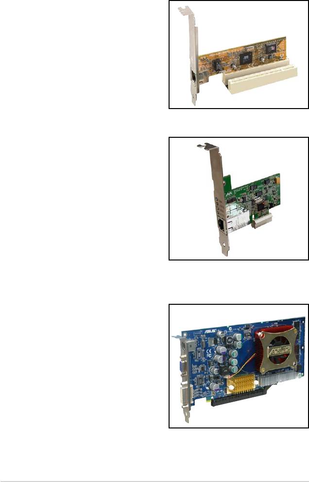
1.8.4 PCI slots
The PCI slots support cards such as
a LAN card, SCSI card, USB card,
and other cards that comply with PCI
specications. The gure shows a LAN
card installed on a PCI slot.
1.8.5 PCI Express x1 slot
This motherboard supports PCI Express
x1 network cards, SCSI cards and other
cards that comply with the PCI Express
specications. The following gure
shows a network card installed on the
PCI Express x1 slot.
1.8.6 PCI Express x16 slot
This motherboard supports PCI Express
x16 graphic cards that comply with the
PCI Express specications. The gure
shows a graphics card installed on the
PCI Express x16 slot.
1-24 Chapter 1: Product introduction
1.9 Jumpers
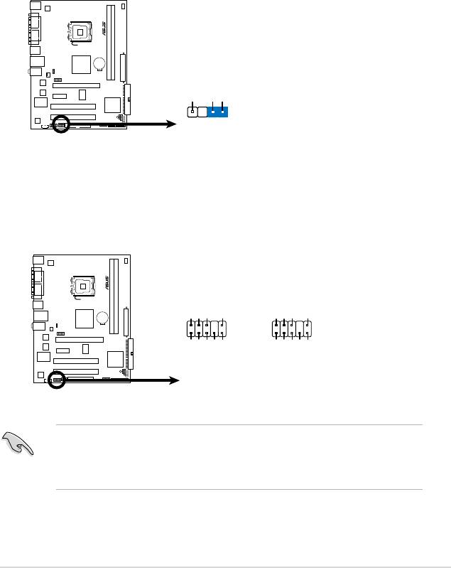
1. Clear RTC RAM (CLRTC)
This jumper allows you to clear the Real Time Clock (RTC) RAM in
CMOS. You can clear the CMOS memory of date, time, and system setup
parameters by erasing the CMOS RTC RAM data. The onboard button
cell battery powers the RAM data in CMOS, which include system setup
information such as system words.
To erase the RTC RAM:
1. Turn OFF the computer and unplug the power cord.
2. Remove the onboard battery.
3. Move the jumper cap from pins 1-2 (default) to pins 2-3. Keep the cap on
pins 2-3 for about 5~10 seconds, then move the cap back to pins 1-2.
4. Reinstall the battery.
5. Plug the power cord and turn ON the computer.
6. Hold down the <Del> key during the boot process and enter BIOS setup
to re-enter data.
Except when clearing the RTC RAM, never remove the cap on CLRTC jumper
default position. Removing the cap will cause system boot failure!
ASUS P5SD2-VM 1-25
CLRTC
2 3
P5 SD2 -V M
1 2
Normal
Clear RTC
(Default)
P5SD2-VM
Clear RTC RAM
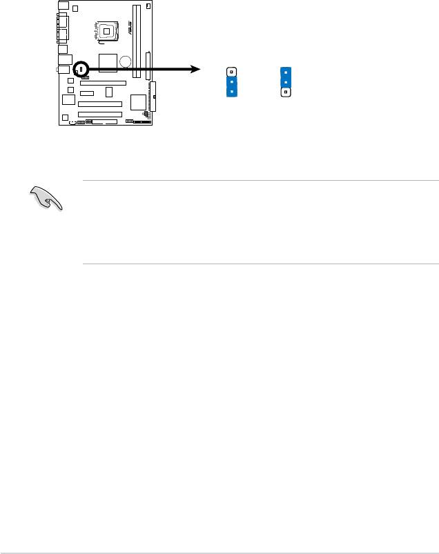
2. Keyboard/mouse/USB device wake-up (3-pin USBPW1-4, USBPW56,
PS2_USBPWR)
This jumper allows you to enable or disable the keyboard/mouse/USB device
wake-up feature. Set this jumper to +5V to wake up the computer from S1
sleep mode (CPU stopped, DRAM refreshed, system running in low power
mode) using the connected keyboard, mouse or USB devices. Set to +5VSB
to wake up from S3 and S4 sleep modes (no power to CPU, DRAM in slow
refresh, power supply in reduced power mode).
• The USB device wake-up feature requires a power supply that can
provide 500mA on the +5VSB lead for each USB port; otherwise,
the system would not power up.
• The total current consumed must NOT exceed the power supply
capability (+5VSB) whether under normal condition or in sleep mode.
1-26 Chapter 1: Product introduction
PS2_USB_PWR
3
2
2
1
P5 SD 2- VM
+5V
+5VSB
(Default)
P5SD2-VM USB Device Wake Up
1.10 Connectors
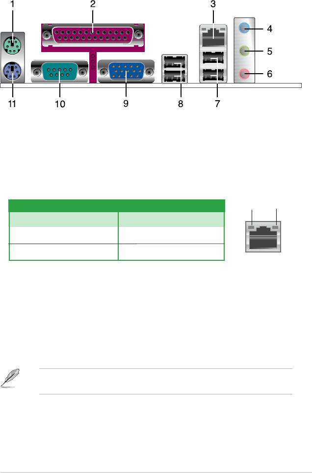
1.10.1 Rear panel connectors
1. PS/2 mouse port (green). This port is for a PS/2 mouse.
2.
Parallel port. This 25-pin port connects a parallel printer, a scanner, or other
devices.
3. LAN (RJ-45) port.
This port allows Network (LAN) through a network hub.
LAN port LED indications
ORANGE
GREEN
ORANGE LED GREEN LED
Status Description Status Description
OFF No link OFF No Link
Orange 100 Mbps connection Green 10 Mbps connection
LAN port
4. Line In port (light blue).
This port connects the tape, CD, DVD player, or
other audio sources.
5. Line Out port (lime).
This port connects a headphone or a speaker. In
4-channel and 6-channel conguration, the function of this port becomes
Front Speaker Out.
6. Microphone port (pink).
This port connects a microphone.
Refer to the audio conguration table below for the function of the audio ports in
2, 4, or 6-channel conguration.
ASUS P5SD2-VM 1-27

Audio 2, 4, or 6-channel conguration
Port Headset 4-speaker 6-speaker
2-speaker
Light Blue Line In Surround Out Surround Out
Lime Line Out Front Speaker Out Front Speaker Out
Pink Mic In Mic Center/Bass
7. USB 2.0 ports 1 and 2.
These two 4-pin Universal Serial Bus (USB) ports
are available for connecting USB 2.0 devices.
8. USB 2.0 ports 3 and 4.
These two 4-pin Universal Serial Bus (USB) ports
are available for connecting USB 2.0 devices.
9. Video Graphics Adapter port.
This 15-pin port is for a VGA monitor or other
VGA-compatible devices.
10. Serial port.
This 9-pin COM1 port is for pointing devices or other serial
devices.
11. PS/2 keyboard port (purple).
This port is for a PS/2 keyboard.
1-28 Chapter 1: Product introduction
1.10.2 Internal connectors
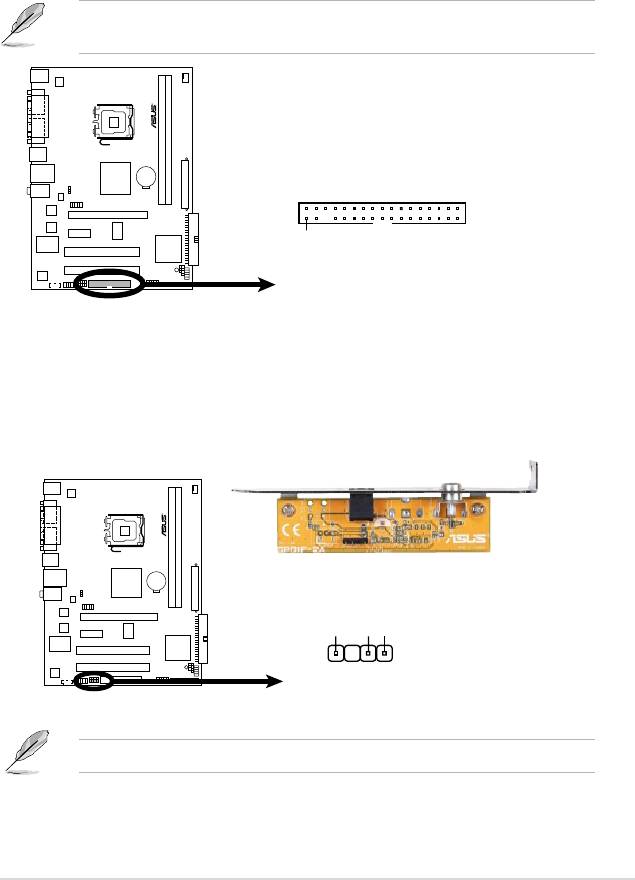
1. Floppy disk drive connector (34-1 pin FLOPPY)
This connector is for the provided oppy disk drive (FDD) signal cable. Insert
one end of the cable to this connector, then connect the other end to the
signal connector at the back of the oppy disk drive.
Pin 5 on the connector is removed to prevent incorrect cable connection when
using a FDD cable with a covered Pin 5.
ASUS P5SD2-VM 1-29
FLOPPY
P5 SD2 -VM
PIN1
NOTE:
Orient the red markings on
the floppy ribbon cable to PIN 1.
P5SD2-VM
Floppy Disk Drive Connector
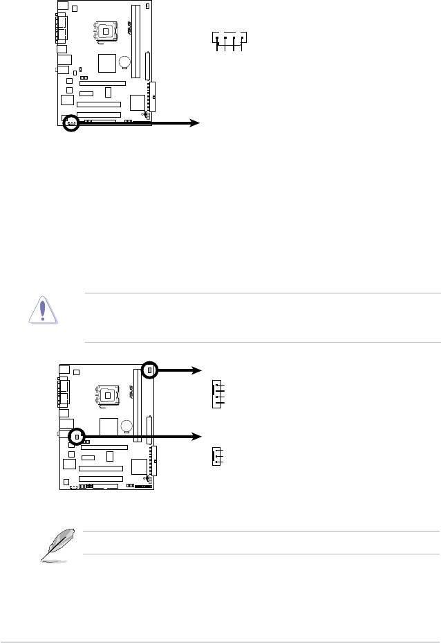
2. Digital Audio connector (4-1 pin SPDIF_OUT)
This connector is for the S/PDIF audio module to allow digital sound output.
Connect one end of the S/PDIF audio cable to this connector and the other
end to the S/PDIF module.
The S/PDIF out module is purchased separately.
+5V
SPDIFOUT
GND
P5 SD2 -V M
SPDIF_OUT
P5SD2-VM Digital Audio Connector
3. IDE connector (40-1 pin PRI_IDE)
The onboard IDE connector is for the Ultra DMA 133/100/66 signal cable.
There are three connectors on each Ultra DMA 133/100/66 signal cable:
blue, black, and gray. Connect the blue connector to the motherboard’s IDE
connector, then select one of the following modes to congure your device.
Drive jumper setting Mode of
Cable connector
device(s)
Single device Cable-Select or Master - Black
Black
Two devices Cable-Select Master
Slave Gray
Master Master Black or gray
Slave Slave
• Pin 20 on the IDE connector is removed to match the covered hole on the
Ultra DMA cable connector. This prevents incorrect insertion when you
connect the IDE cable.
• Use the 80-conductor IDE cable for Ultra DMA
133/100/66 IDE devices.
If any device jumper is set as “Cable-Select,” make sure all other device
jumpers have the same setting.
1-30 Chapter 1: Product introduction
P5 SD 2- VM
PRI_IDE
P5SD2-VM
IDE Connector
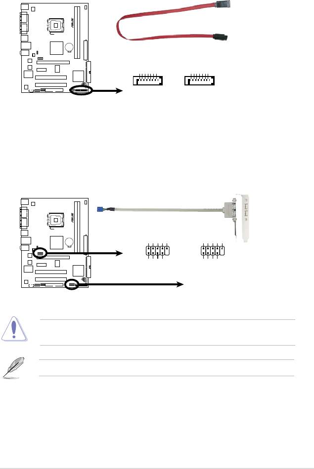
4. Serial ATA connectors (7-pin SATA1, SATA2)
These connectors are for the Serial ATA signal cables for Serial ATA hard disk
drives.
ASUS P5SD2-VM 1-31
GND
RSATA_RXP2
RSATA_RXN2
GND
RSATA_TXN2
RSATA_TXP2
GND
GND
RSATA_RXP1
RSATA_RXN1
GND
RSATA_TXN1
RSATA_TXP1
GND
P5 SD 2- VM
SATA2
SATA1
P5SD2-VM SATA Connectors
5. USB connectors (10-1 pin USB56 78)
These connectors are for USB 2.0 ports. Connect the USB module cable
to any of these connectors, then install the module to a slot opening at the
back of the system chassis. These USB connectors comply with USB 2.0
specication that supports up to 480 Mbps connection speed.
Never connect a 1394 cable to the USB connectors. Doing so will damage the
motherboard!
USB78
USB56
USB+5V
USB_P8-
USB_P8+
GND
NC
USB+5V
USB_P6-
USB_P6+
GND
NC
1
1
P5 SD 2- VM
GND
GND
USB+5V
USB_P7-
USB+5V
USB_P7+
USB_P5-
USB_P5+
P5SD2-VM
USB 2.0 Connectors
The USB module is purchased separately.
6. Optical drive audio connector (4-pin CD)
These connectors allow you to receive stereo audio input from sound sources
such as a CD-ROM, TV tuner, or MPEG card.
1-32 Chapter 1: Product introduction
P5SD2-VM
Internal Audio Connecto
r
CD
(black)
Ground
Ground
P5 SD 2- VM
Left Audio Channel
Right Audio Channel
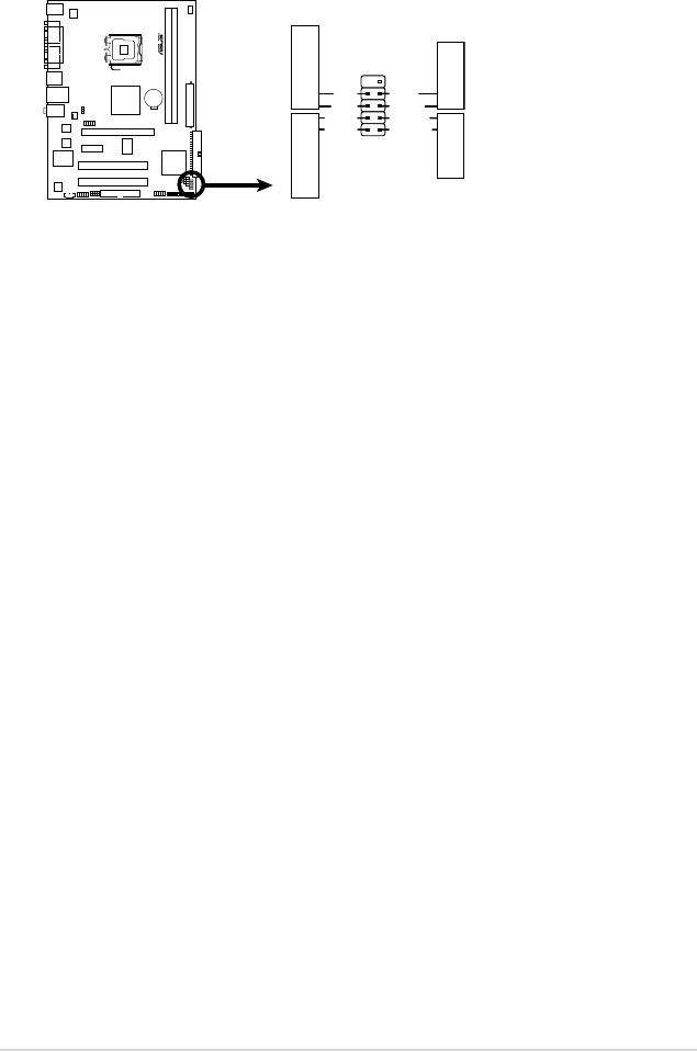
7. CPU and chassis fan connectors
(4-pin CPU_FAN, 3-pin CHA_FAN)
The fan connectors support cooling fans of 350 mA ~ 2000 mA (24 W max.)
or a total of 1 A ~ 7 A (84 W max.) at +12V. Connect the fan cables to the
fan connectors on the motherboard, making sure that the black wire of each
cable matches the ground pin of the connector.
Do not forget to connect the fan cables to the fan connectors. Insufcient air
ow inside the system may damage the motherboard components. These are
not jumpers! Do not place jumper caps on the fan connectors!
CPU_FAN
GND
CPU FAN PWR
CPU FAN IN
CPU FAN PW
P5 SD 2- VM
P5SD2-VM
Fan Connectors
M
CHA_FAN
GND
+12V
Rotation
Only the CPU-FAN connector supports the ASUS Advanced Q-Fan feature
8. Chassis intrusion connector (4-1 pin CHASSIS)
This connector is for a chassis-mounted intrusion detection sensor or switch.
Connect one end of the chassis intrusion sensor or switch cable to this
connector. The chassis intrusion sensor or switch sends a high-level signal to
this connector when a chassis component is removed or replaced. The signal
is then generated as a chassis intrusion event.
By default , the pin labeled “Chassis Signal” and “ Ground” are shorted with
a jumper cap. Remove the jumper caps only when you intend to use the
chassis intrusion detection feature.
9. Front panel audio connector (10-1 pin AAFP)
This connector is for a chassis-mounted front panel audio I/O module that
supports either HD Audio or legacy AC`97 audio standard. Connect one end
of the front panel audio I/O module cable to this connector.
•
We recommend that you connect a high-denition front panel audio module
to this connector to avail of the motherboard’s high-denition audio capability.
•
By default, this connector is set to HD Audio.
ASUS P5SD2-VM 1-33
CHASSIS
+5VSB_MB
Chassis Signal
GND
P5 SD 2- VM
(Default)
P5SD2-VM Intrusion Connector
Azalia-compliant
Legacy AC’97-compliant
pin definition
pin definition
AGND
PRESENSE#
MIC2_JD
HP_HD
AGND
NC
NC
NC
AAFP
NC
P5 SD 2- VM
HP_R
HP_L
MIC2_L
MIC2_R
MIC2_L
MIC2_R
Line out_R
Line out_L
Jack_Sense
P5SD2-VM Front Panel Audio Connector

10. ATX power connectors (24-pin EATXPWR, 4-pin ATX12V)
These connectors are for ATX power supply plugs. The power supply plugs
are designed to t these connectors in only one orientation. Find the proper
orientation and push down rmly until the connectors completely t.
•
For a fully congured system, we recommend that you use a power supply
unit (PSU) that complies with ATX 12 V Specication 2.0 (or later version)
and provides a minimum power of 400 W.
• Do not forget to connect the 4-pin ATX12V power plug; otherwise, the
system will not boot.
• Use of a PSU with a higher power output is recommended when
conguring a system with more power-consuming devices. The system
may become unstable or may not boot up if the power is inadequate.
• The ATX 12 V Specication 2.0-compliant (400W) PSU has been tested to
support the motherboard power requirements.
1-34 Chapter 1: Product introduction
ATX12V
EATXPWR
+12V DC
+12V DC
+3 Volts
Ground
GND
GND
+12 Volts
+5 Volts
+12 Volts
+5 Volts
+5V Standby
+5 Volts
Power OK
-5 Volts
Ground
Ground
+5 Volts
Ground
Ground
Ground
P5 SD 2- VM
+5 Volts
PSON#
Ground
Ground
+3 Volts
-12 Volts
+3 Volts
+3 Volts
P5SD2-VM
ATX Power Connector
11. System panel connector (10-1 pin PANEL)
This connector supports several chassis-mounted functions.
•
System power LED (2-pin PLED)
This 2-pin connector is for the system power LED. Connect the chassis
power LED cable to this connector. The system power LED lights up when
you turn on the system power, and blinks when the system is in sleep mode.
•
Hard disk drive activity LED (2-pin IDE_LED)
This 2-pin connector is for the HDD Activity LED. Connect the HDD Activity
LED cable to this connector. The IDE LED lights up or ashes when data is
read from or written to the HDD.
•
System warning speaker (4-pin SPEAKER)
This 4-pin connector is for the chassis-mounted system warning speaker. The
speaker allows you to hear system beeps and warnings.
•
ATX power button/soft-off button (2-pin PWRSW)
This connector is for the system power button. Pressing the power button
turns the system on or puts the system in sleep or soft-off mode depending
on the BIOS settings. Pressing the power switch for more than four seconds
while the system is ON turns the system OFF.
•
Reset button (2-pin RESET)
This 2-pin connector is for the chassis-mounted reset button for system
reboot without turning off the system power.
ASUS P5SD2-VM 1-35
F_PANEL
GND
Reset
PWR BTN
PWR
Ground
RESET
PLED-
IDELED-
PLED+
IDELED+
P5 SD 2- VM
HD LED
PWR LED
P5SD2-VM
System Panel Connector

1-36 Chapter 1: Product introduction
