Asus P1-P5945GCX: инструкция
Раздел: Компьютерная техника, комплектующие, аксессуары
Тип: Мультимедийный Компьютер

Инструкция к Мультимедийному Компьютеру Asus P1-P5945GCX
English
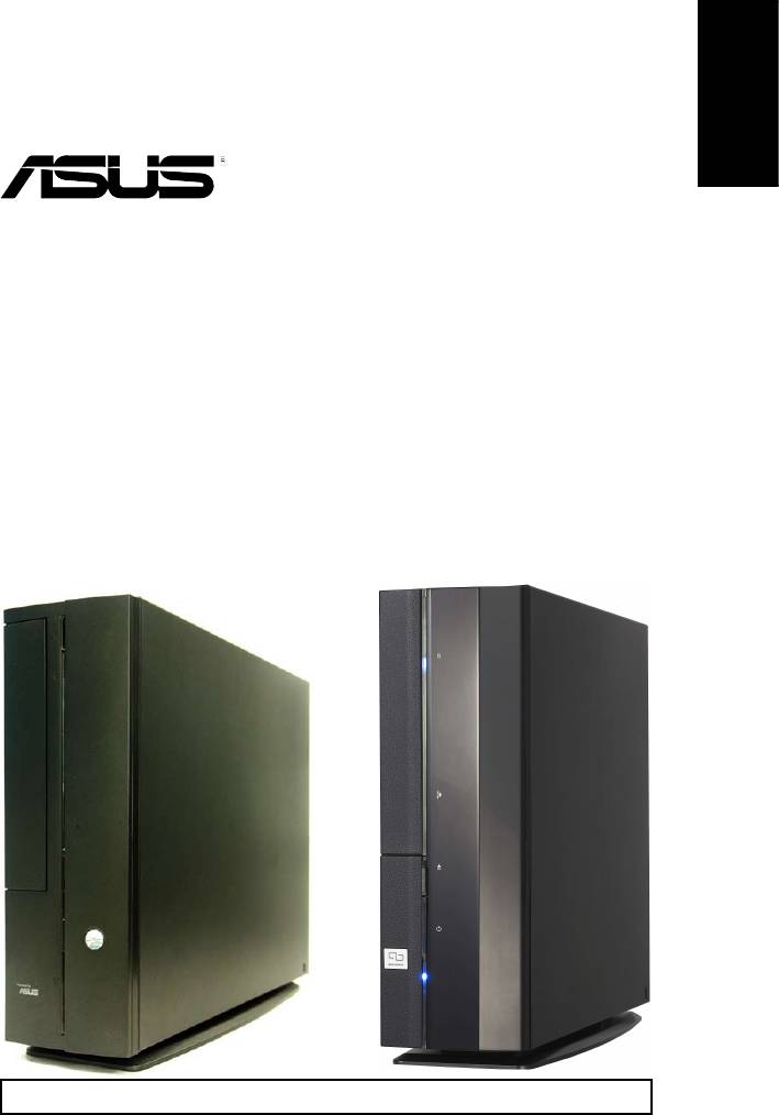
P1-P5945G/P2-P5945G
ASUS PC (Desktop Barebone)
Installation Manual
Download the latest manual from the ASUS website: www.asus.com
English
2 Installation manual
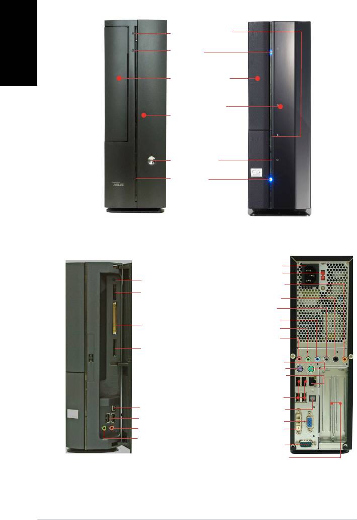
Front panel features
Close
Optical drive eject
button
HDD LED
Optical drive bay
cover
Press to open the
front panel cover
Power button
Power LED
Front panel features
Rear panel features
Open
Power connector
Voltage selector*
Reset button
Center/Sub out
MS/MS Pro card slot
Rear Surround L/R
Side Surround L/R
Line In
®
CompactFlash
card
Line Out
slot
Rear MIC
SD/MMC card slot
PS/2 mouse port
PS/2 keyboard port
LAN (RJ-45) port
USB 2.0 ports
4-pin IEEE 1394 port
SPDIF Out port
USB 2.0 ports
VGA port
Headphone port
DVI-D port
Microphone port
Serial port
PCI slot metal brackets
* The system’s power supply unit has a
115 V/230 V voltage selector switch located near the power connector. Use this switch
to select the correct system input voltage according to the voltage supply in your area.
English
3Installation manual
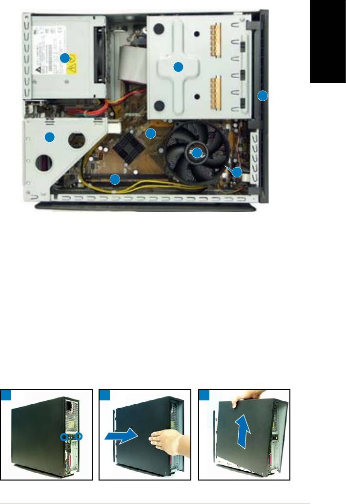
Internal components
3
1
2
5
4
8
7
6
1. 5.25-inch optical drive and
5. ASUS motherboard
3.5 inch hard disk drive cage
6. DIMM sockets
2. Front panel cover
7. LGA775 socket
(under the CPU
3. Power supply unit
fan and heatsink assembly)
4. PCI card riser bracket
8. CPU fan and heatsink assembly
(connected to the
motherboard PCI slot)
Removing the cover
1. Remove the cover screws. Keep the screws for later use.
2. Pull the cover slightly toward the rear panel.
3. Lift the cover, then set aside.
1
32
English
4 Installation manual
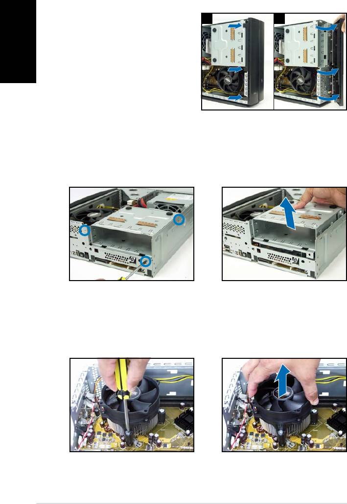
Removing the front panel cover
1. Lift the front panel cover
1 2
hooks outward.
2. Carefully remove the front
panel cover, then set it aside.
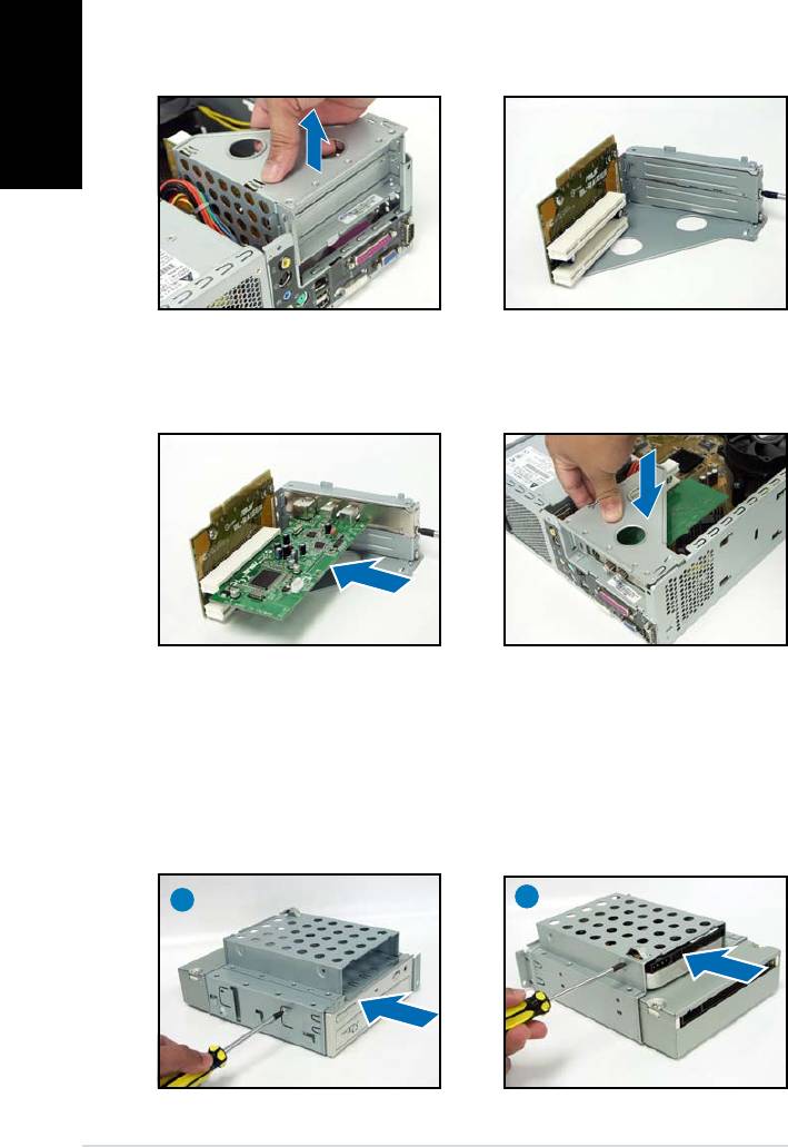
Removing the storage drive assembly
1. Lay the system on its side,
2. Lift the storage drive assembly,
then locate and remove three
then set aside.
storage drive assembly screws.
Removing the CPU fan and heatsink
1. Disconnect the CPU fan cable.
3. Lift the CPU fan and heatsink
assembly, then set aside.
2. Loosen the CPU fan and
heatsink assembly screws.
English
5Installation manual
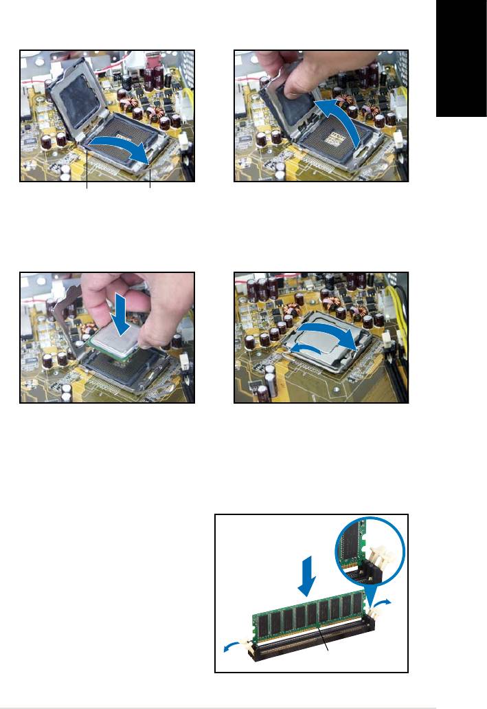
Installing the CPU
1. Unlock the load lever, then lift
2. Lift the load plate, then
to a 90º-100º angle.
remove the PnP cap.
Load leverRetention tab
3. Install the CPU. The CPU ts in
4. Close the load plate, then lock
only one orientation.
the load lever.
5. Reinstall the CPU fan and heatsink assembly, then reconnect the CPU
fan cable to the CPU fan connector on the motherboard. Refer to the
instructions in the previous section for details.
Installing a DIMM
1. Locate the DIMM sockets in the
Unlocked
motherboard.
retaining clip
2. Unlock a DIMM socket by
pressing the retaining clips
outward.
3. Align a DIMM on the socket
such that the notch on the
DIMM matches the break on the
socket.
DDR DIMM notch
English
6 Installation manual
Installing an expansion card
1. Lift the PCI riser card assembly
2. Remove the metal cover
to remove.
opposite the slot that you
intend to use.
3. Insert the card connector to
4. Reinstall the PCI riser card
the slot, then press the card
assembly. Make sure that the
rmly until it ts in place.
riser card connector sits properly
Secure the card with a screw.
on the motherboard PCI slot.
Installing optical and storage drives
1. Turn the storage drive assembly upside down with the 3.5-inch bay on
top of the 5.25-inch bay.
2. Insert the optical drive upside down to the 5.25-inch bay, then secure
it with two screws on both sides.
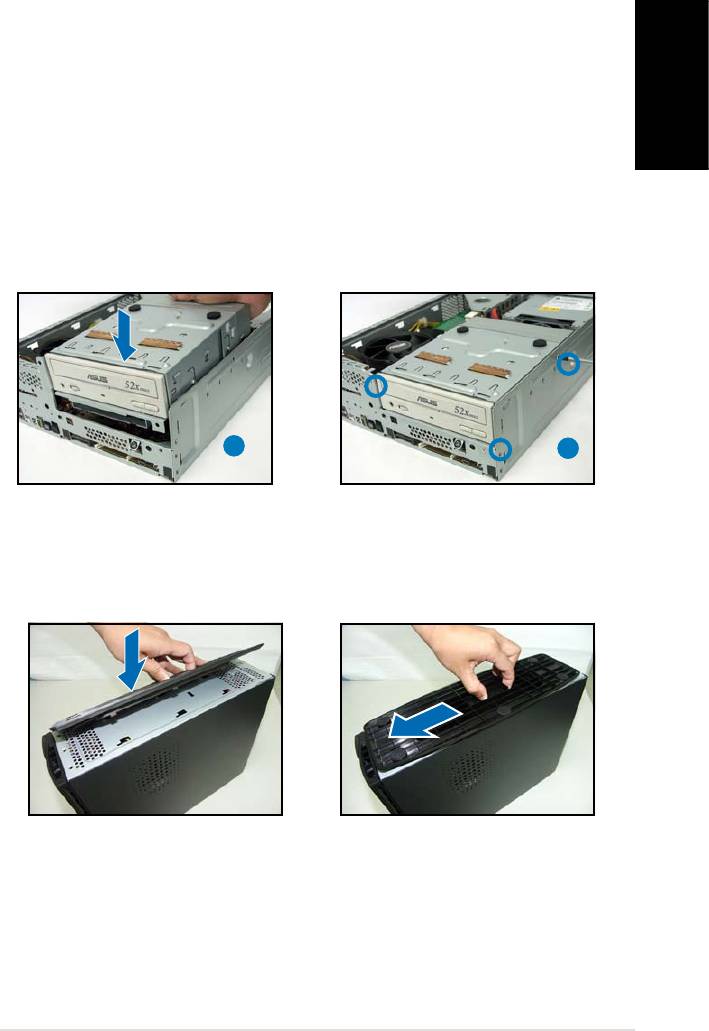
3. Turn the storage drive assembly, insert the hard disk drive upside down to
the 3.5-inch bay, then secure it with two screws on both sides.
2
3
English
7Installation manual
Reinstalling the storage drive assembly
Before reinstalling the storage drive assembly, connect the IDE/SATA and
power plugs to the IDE/SATA and power connectors at the back of the
drives.
1. Connect the black plug of the IDE cable to the optical drive, then the
gray plug to the hard disk drive. If you have the SATA HDD, connect
the SATA cable to the SATA HD.
2. Connect the 4-pin power plugs to the power connectors at the back
of the drives.
3. Install the storage drive assembly to the chassis.
4. Secure the storage drive assembly with three screws.
3
4
Installing the foot stand
1. Match the foot stand hooks to
2. Pull the foot stand to the
the holes on the chassis.
direction of the arrow until the
lock clicks in place.
To remove the foot stand, lift the lock, then slightly push the foot stand to
the direction of the rear panel until it disengages from the chassis.
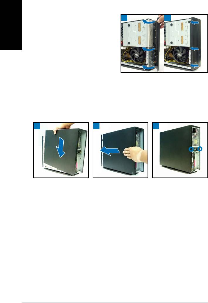
Reinstalling the front panel cover
English
1. Insert the front panel cover
1 2
tabs to the holes at the right
side of the chassis, then close.
2. Insert the front panel cover
hooks to the chassis tabs until
the front panel cover ts in
place.
Reinstalling the cover
1. Install the cover to the chassis. Make sure the cover tabs t the chassis rails.
2. Push the cover toward the front panel until it ts in place.
3. Secure the cover with two screws.
1
2
3
8 Installation manual
Оглавление
- P1-P5945G/P2-P5945G
- P1-P5945G/P2-P5945G ASUS PC (Système barebone)
- P1-P5945G/P2-P5945G ASUS PC (Desktop Barebone)
- P1-P5945G/P2-P5945G ASUS PC (Servidor Barebone de Sobremesa)
- P1-P5945G/P2-P5945G ASUS ПК (баребон)
- P1-P5945G/P2-P5945G ASUS PC (sistema barebone para desktop)
- P1-P5945G/P2-P5945G
- P1-P5945G/P2-P5945G ASUS Komputer PC (Desktop Bare- bone)
- P1-P5945G/P2-P5945G ASUS Asztali barebone szàmìtògèp


