Asus V2-PH1: инструкция
Раздел: Бытовая, кухонная техника, электроника и оборудование
Тип: Компьютер
Инструкция к Компьютеру Asus V2-PH1
English
Vintage2-PH1
Barebone System
Quick Installation Guide
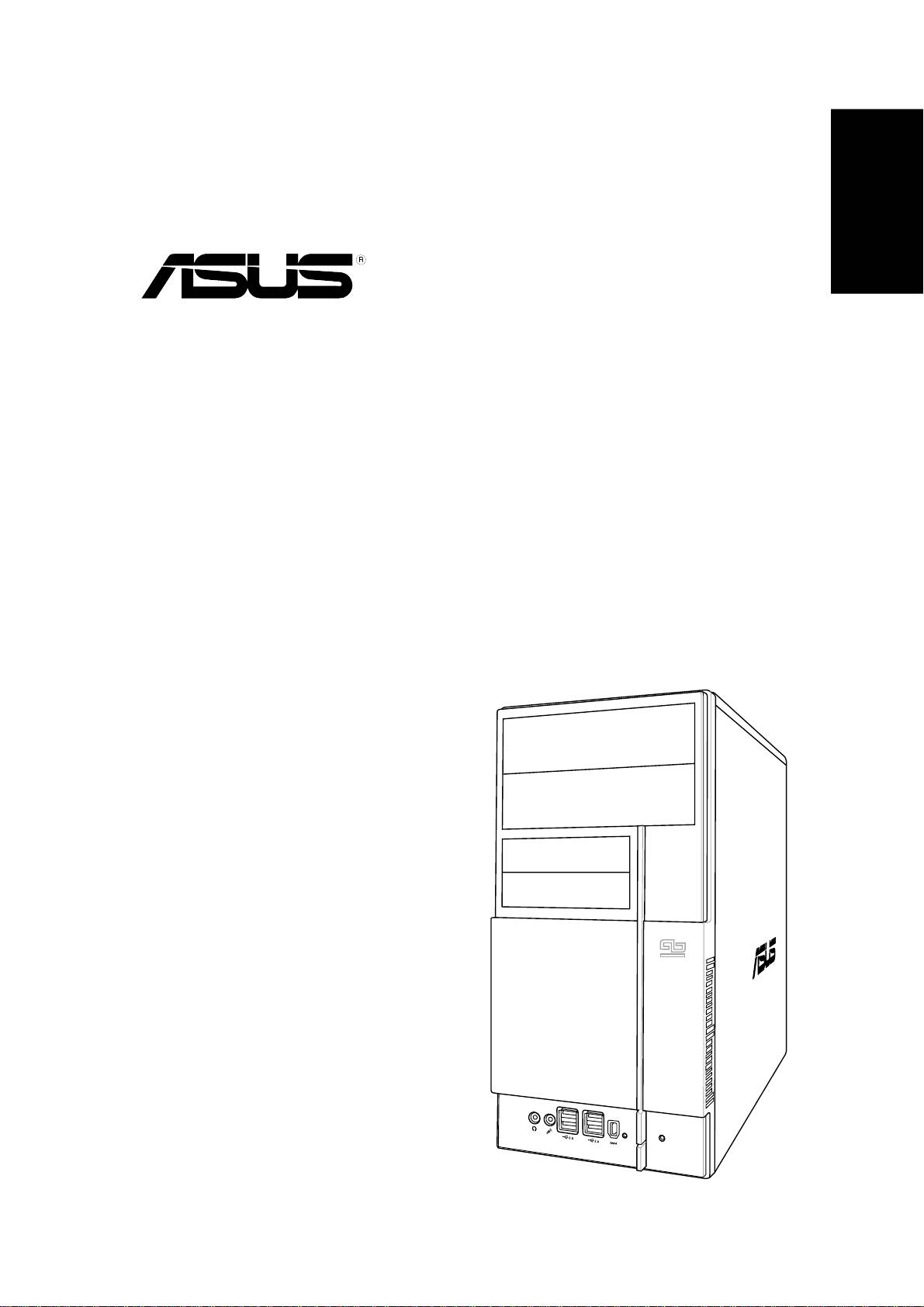
Front panel features
English
5.25-inch drive5.25-inch drive
5.25-inch drive5.25-inch drive
5.25-inch drive
bay coverbay cover
bay coverbay cover
bay cover
3.5-inch drive bay3.5-inch drive bay
3.5-inch drive bay3.5-inch drive bay
3.5-inch drive bay
covercover
covercover
cover
USB 2.0 portsUSB 2.0 ports
USB 2.0 portsUSB 2.0 ports
USB 2.0 ports
Microphone portMicrophone port
Microphone portMicrophone port
Microphone port
IEEE 1394 portIEEE 1394 port
IEEE 1394 portIEEE 1394 port
IEEE 1394 port
Power buttonPower button
Power buttonPower button
Power button
Headphone portHeadphone port
Headphone portHeadphone port
Headphone port
Reset buttonReset button
Reset buttonReset button
Reset button
HDD LEDHDD LED
HDD LEDHDD LED
HDD LED
Rear panel features
Power connectorPower connector
Power connectorPower connector
Power connector
Voltage selectorVoltage selector
Voltage selectorVoltage selector
Voltage selector
Power supply fanPower supply fan
Power supply fanPower supply fan
Power supply fan
Cover screwCover screw
Cover screwCover screw
Cover screw
PS/2 mouse portPS/2 mouse port
PS/2 mouse portPS/2 mouse port
PS/2 mouse port
PS/2 keyboard portPS/2 keyboard port
PS/2 keyboard portPS/2 keyboard port
PS/2 keyboard port
Serial portSerial port
Serial portSerial port
Serial port
Parallel portParallel port
Parallel portParallel port
Parallel port
VGA port VGA port
VGA port VGA port
VGA port
Chassis fan ventsChassis fan vents
Chassis fan ventsChassis fan vents
Chassis fan vents
IEEE 1394 portIEEE 1394 port
IEEE 1394 portIEEE 1394 port
IEEE 1394 port
USB 2.0 portsUSB 2.0 ports
USB 2.0 portsUSB 2.0 ports
USB 2.0 ports
BASS
C T R
S P K
SIDE
S P K
REAR
LAN (RJ-45) portLAN (RJ-45) port
LAN (RJ-45) portLAN (RJ-45) port
LAN (RJ-45) port
8-channel8-channel
8-channel8-channel
8-channel
MIC IN
FRONT
IN
LINE
audio portsaudio ports
audio portsaudio ports
audio ports
Cover screwCover screw
Cover screwCover screw
Cover screw
Expansion slotExpansion slot
Expansion slotExpansion slot
Expansion slot
Metal bracket lockMetal bracket lock
Metal bracket lockMetal bracket lock
Metal bracket lock
metal bracketsmetal brackets
metal bracketsmetal brackets
metal brackets
22
22
2
Quick installation guideQuick installation guide
Quick installation guideQuick installation guide
Quick installation guide
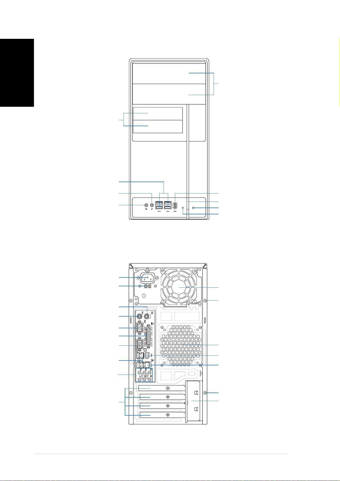
Internal components
55
55
5
22
22
2
English
PS/2KBMS
CPU_FAN
T: Mouse
B: Keyboard
33
33
3
COM1
ATX12V
I/O
LGA775
Super
PWR_FAN
11
11
1
66
66
6
FLOPPY
PARALLEL PORT
44
44
¤
4
VGA
Bottom:
Top:
COM2
99
99
9
USB1
88
88
8
77
77
USB2
1394
7
LAN_USB34
Intel
¤
GMCH
DDR DIMM_A1 (64 bit,240-pin module)
DDR DIMM_A2 (64 bit,240-pin module)
DDR DIMM_B1 (64 bit,240-pin module)
DDR DIMM_B2 (64 bit,240-pin module)
AUDIO
945G
EATXPWR
CHA_FAN
PCIEX16
PRI_IDE
1010
1010
10
82573L
Intel
PCI1
SB_PWR
Intel
¤
Intel FWH
4Mb
11
11
1
11
11
1
ICH7
PLED
CHASSIS
SPEAKER
11
11
1
33
33
3
PCI2
CD
SATA4SATA 3
CR2032 3V
ALC882
PCIEX1_1
TSB43AB22A
TI
Lithium Cell
SATA 1 SATA 2
11
11
1
22
22
CMOS Power
2
CLRTC
BUZZ
F_PANEL
AAFP
SPDIF_OUT
IE1394_2
USB56
USB78
1. Front panel cover
8. ASUS motherboard
2. 5.25-inch optical drive bays
9. Chassis fan
3. Hard disk drive bay
10. PCI Express x16 slot
4. Floppy disk drive bay
11. PCI slots
5. Power supply unit
12. PCI Express x1 slot
6. CPU socket
13. Metal bracket lock
7. DIMM sockets
Selecting the voltage
The system’s power supply unit has a
115 V/230 V voltage selector switch
located beside the power connector.
Use this switch to select the
appropriate system input voltage
according to the voltage supply in your
area.
If the voltage supply in your area is
100-127 V, set the switch to 115 V.
If the voltage supply in your area is
200-240 V, set the switch to 230 V.
Quick installation guideQuick installation guide
Quick installation guideQuick installation guide
Quick installation guide
33
33
3
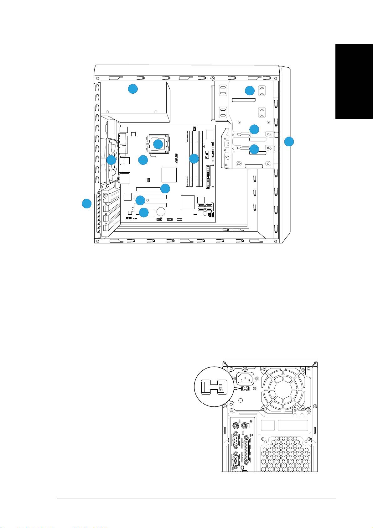
Removing the side cover and
front panel assembly
English
1. Remove the cover screws on the rear panel.
2. Pull the side cover toward the rear panel until its hooks disengage
from the chassis tab holes. Set the side cover aside.
3. Locate the front panel assembly hooks, then lift them until they
disengage from the chassis.
4. Swing the front panel assembly to the right, until the hinge-like tabs
on the right side of the assembly are exposed.
5. Remove the front panel assembly, then set aside.
33
44
44
4
33
3
Air ductAir duct
Air ductAir duct
Air duct
11
11
1
44
44
4
33
33
3
22
22
2
11
11
1
44
44
4
33
33
3
22
22
2
Chassis tab holesChassis tab holes
Chassis tab holesChassis tab holes
Chassis tab holes
33
33
3
Installing a CPU
®
®
• Your boxed Intel
Pentium
4 LGA775 processor package should
come with installation instructions for the CPU, heatsink, and the
retention mechanism. If the instructions in this section do not match
the CPU documentation, follow the latter.
•
Check your motherboard to make sure that the PnP cap is on the
CPU socket and the socket contacts are not bent. Contact your
retailer immediately if the PnP cap is missing, or if you see any
damage to the PnP cap/socket contacts/motherboard components.
ASUS will shoulder the cost of repair only if the damage is shipment/
transit-related.
•
Keep the cap after installing the motherboard. ASUS will process
Return Merchandise Authorization (RMA) requests only if the
motherboard comes with the cap on the LGA775 socket.
• The product warranty does not cover damage to the socket
contacts resulting from incorrect CPU installation/removal, or
misplacement/loss/incorrect removal of the PnP cap.
44
44
4
Quick installation guideQuick installation guide
Quick installation guideQuick installation guide
Quick installation guide
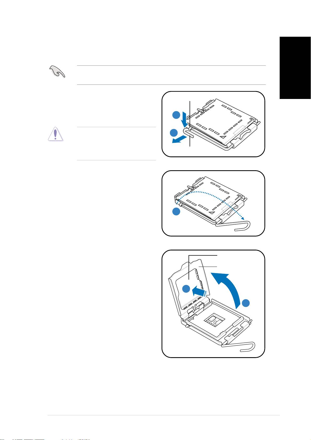
To install a CPU:
1. Locate the CPU socket on the motherboard.
Before installing the CPU, make sure that the socket box is facing
towards you and the load lever is on your left.
English
2. Press the load lever with your
Retention tabRetention tab
Retention tabRetention tab
Retention tab
thumb (A), then move it to the
left (B) until it is released from
AA
AA
A
the retention tab.
To prevent damage to the
BB
BB
B
socket pins, do not remove
the PnP cap unless you are
Load lever
Load leverLoad lever
Load leverLoad lever
installing a CPU.
3. Lift the load lever in the
direction of the arrow to a 135º
angle.
33
33
3
4. Lift the load plate with your
PnP capPnP cap
PnP capPnP cap
PnP cap
thumb and forefinger to a 100º
Load plateLoad plate
Load plateLoad plate
Load plate
angle (A), then push the PnP
cap from the load plate window
to remove (B).
BB
BB
B
AA
AA
A
Quick installation guideQuick installation guide
Quick installation guideQuick installation guide
Quick installation guide
55
55
5
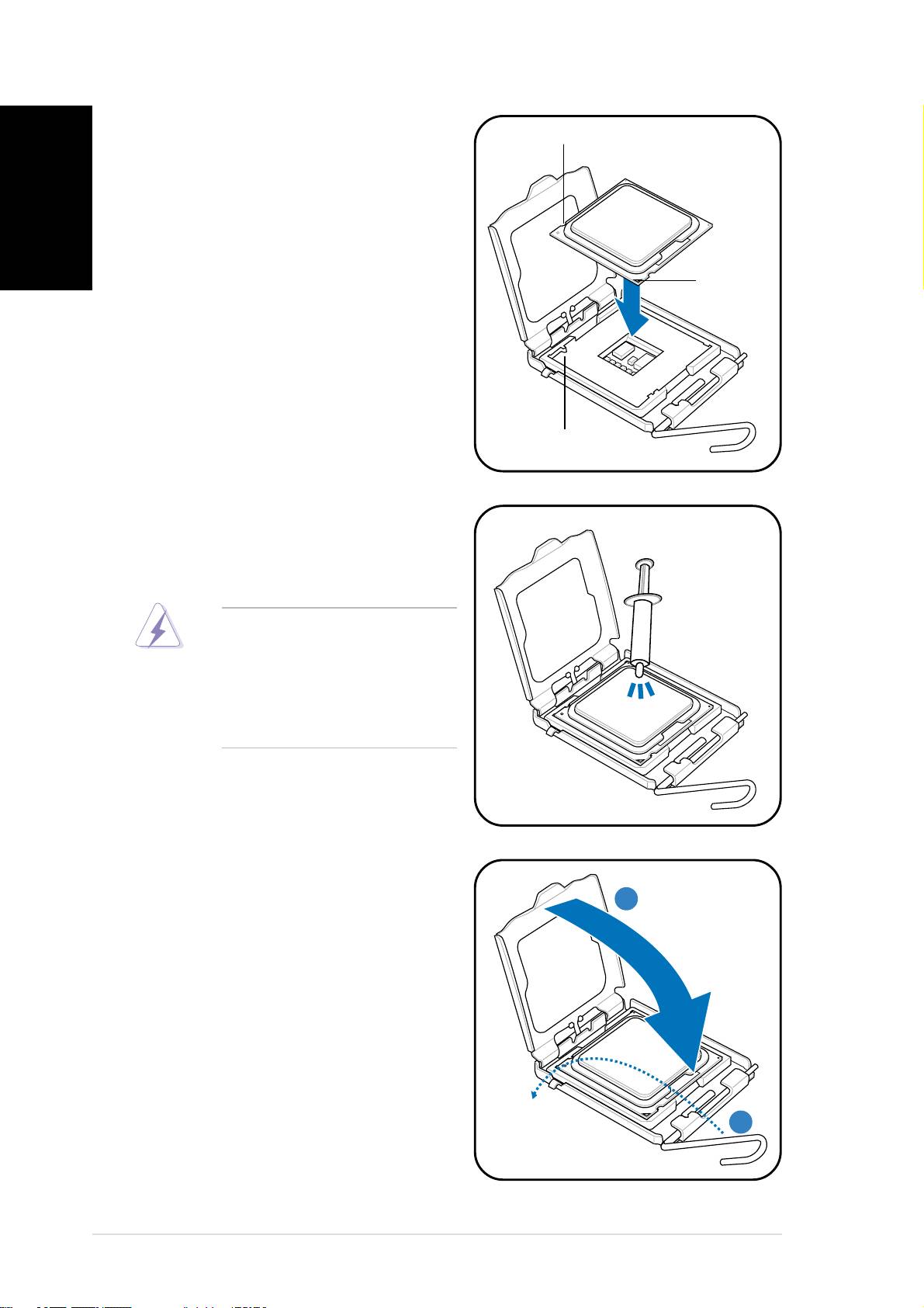
5. Position the CPU over the
CPU notchCPU notch
CPU notchCPU notch
CPU notch
English
socket, making sure that the
gold triangle is on the
bottom-left corner of the
socket then fit the socket
alignment key into the CPU
notch.
GoldGold
GoldGold
Gold
triangletriangle
triangletriangle
triangle
markmark
markmark
mark
Alignment keyAlignment key
Alignment keyAlignment key
Alignment key
6. Apply Thermal Interface Material
on the CPU before reinstalling
the heatsink and fan assembly.
DO NOT DO NOT
DO NOT DO NOT
DO NOT eat the Thermal
Interface Material. If it gets
into your eyes or touches
your skin, make sure to wash
it off immediately, and seek
professional medical help.
7. Close the load plate (A), then
push the load lever (B) until it
AA
AA
A
snaps into the retention tab.
BB
BB
B
66
66
6
Quick installation guideQuick installation guide
Quick installation guideQuick installation guide
Quick installation guide
Installing the CPU fan and heatsink assembly
®
®
®
®
The Intel
Pentium
4/Intel
Pentium
D LGA775 processor requires a
specially designed heatsink and fan assembly to ensure optimum thermal
condition and performance.
®
®
English
• When you buy a boxed Intel
Pentium
4 processor, the package
includes the CPU fan and heatsink assembly. If you buy a CPU
®
separately, make sure that you use only Intel
-certified
multi-directional heatsink and fan.
®
®
• Your Intel
Pentium
4 LGA775 heatsink and fan assembly comes in
a push-pin design and requires no tool to install.
If you purchased a separate CPU heatsink and fan assembly, make sure
that a Thermal Interface Material is properly applied to the CPU heatsink
or CPU before you install the heatsink and fan assembly.
To install the CPU heatsink and fan:
AA
AA
A
1. Place the heatsink on top of the
BB
BB
B
installed CPU, making sure that
BB
BB
B
the four fasteners match the
holes on the motherboard.
AA
AA
A
2. Push down two fasteners at a
time in a diagonal sequence to
secure the heatsink and fan
assembly in place.
A
B
11
11
1
11
11
1
B
A
3. When the fan and heatsink assembly is in place, connect the CPU fan
cable to the connector on the motherboard.
Do not forget to connect the CPU fan connector! Hardware monitoring
errors can occur if you fail to plug this connector.
Quick installation guideQuick installation guide
Quick installation guideQuick installation guide
Quick installation guide
77
77
7
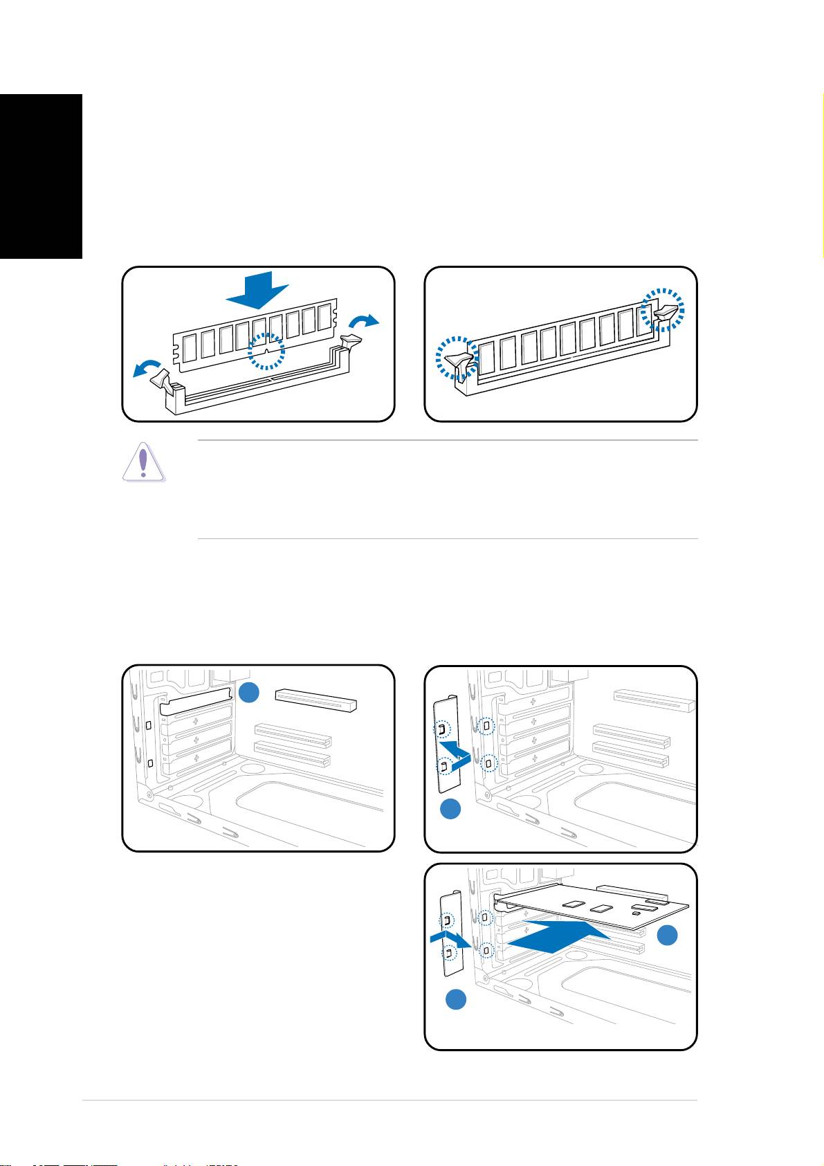
Installing a DIMM
English
1. Locate the DIMM sockets in the motherboard.
2. Unlock a DIMM socket by pressing the retaining clips outward.
3. Align a DIMM on the socket such that the notch on the DIMM matches
the break on the socket.
4. Push the DIMM to the socket until the retaining clips snap inward.
• Unplug the power supply before adding or removing DIMMs. Failure to
do so may cause damage to the motherboard and/or components.
• A DDR DIMM is keyed with a notch so that it fits in only one direction.
Do not force a DIMM into a socket to avoid damaging the DIMM.
Installing an expansion card
1. Remove the metal cover
2. Remove the metal bracket
opposite the slot that you
lock.
intend to use.
11
11
1
2
22
22
3. Insert the card connector to
the slot, then press the card
firmly until it fits in place.
33
33
3
4. Replace the metal bracket
lock.
4
44
44
88
88
8
Quick installation guideQuick installation guide
Quick installation guideQuick installation guide
Quick installation guide
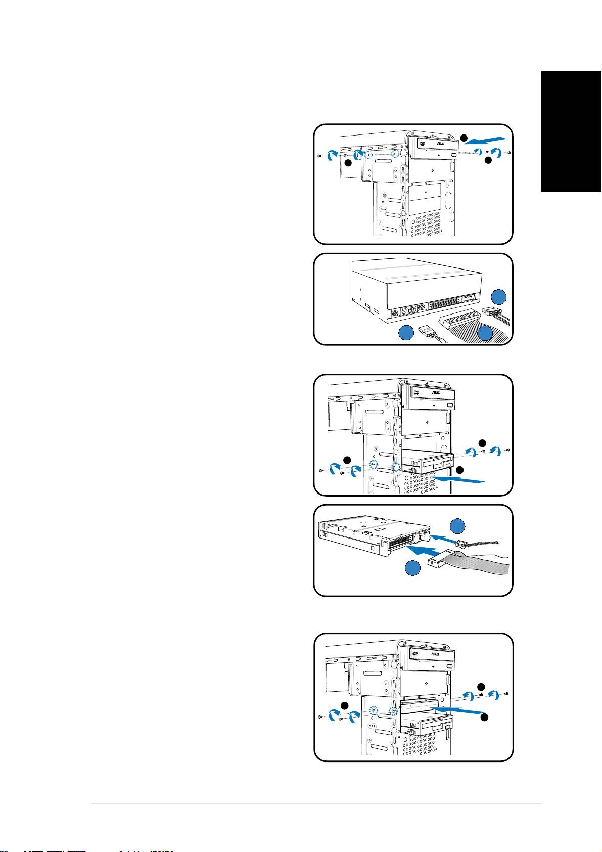
Installing storage drives
Optical drive
Optical driveOptical drive
Optical driveOptical drive
1. Place the chassis upright, then
2
remove the upper 5.25” drive
English
bay metal plate cover.
3
3
2. Insert the optical drive to the
bay, then carefully push the
drive until its screw holes align
with the holes on the bay.
3. Secure the optical drive with two
screws on both sides of the bay.
4. Connect the audio (A), IDE (B),
and power (C) plugs to
CC
CC
C
connectors at the back of the
drive.
AA
AA
A
BB
BB
B
Floppy disk drive
Floppy disk driveFloppy disk drive
Floppy disk driveFloppy disk drive
1. Place the chassis upright, then
remove the lower 3.5” drive bay
metal plate cover.
2. Insert the floppy disk drive to
3
the bay, then carefully push the
3
drive until its screw holes align
2
with the holes on the bay.
3. Secure the floppy disk drive with
two screws on both sides of the
bay.
BB
BB
B
4. Connect the signal (A) and
power (B) plugs to connectors
AA
AA
A
at the back of the drive.
Hard disk drive
Hard disk driveHard disk drive
Hard disk driveHard disk drive
1. Place the chassis upright, then
remove the upper 3.5” drive bay
metal plate cover.
3
2. Insert the hard disk drive to the
bay, then carefully push the
3
2
drive until its screw holes align
with the holes on the bay.
3. Secure the hard disk drive with
two screws on both sides of the
bay.
Quick installation guideQuick installation guide
Quick installation guideQuick installation guide
Quick installation guide
99
99
9
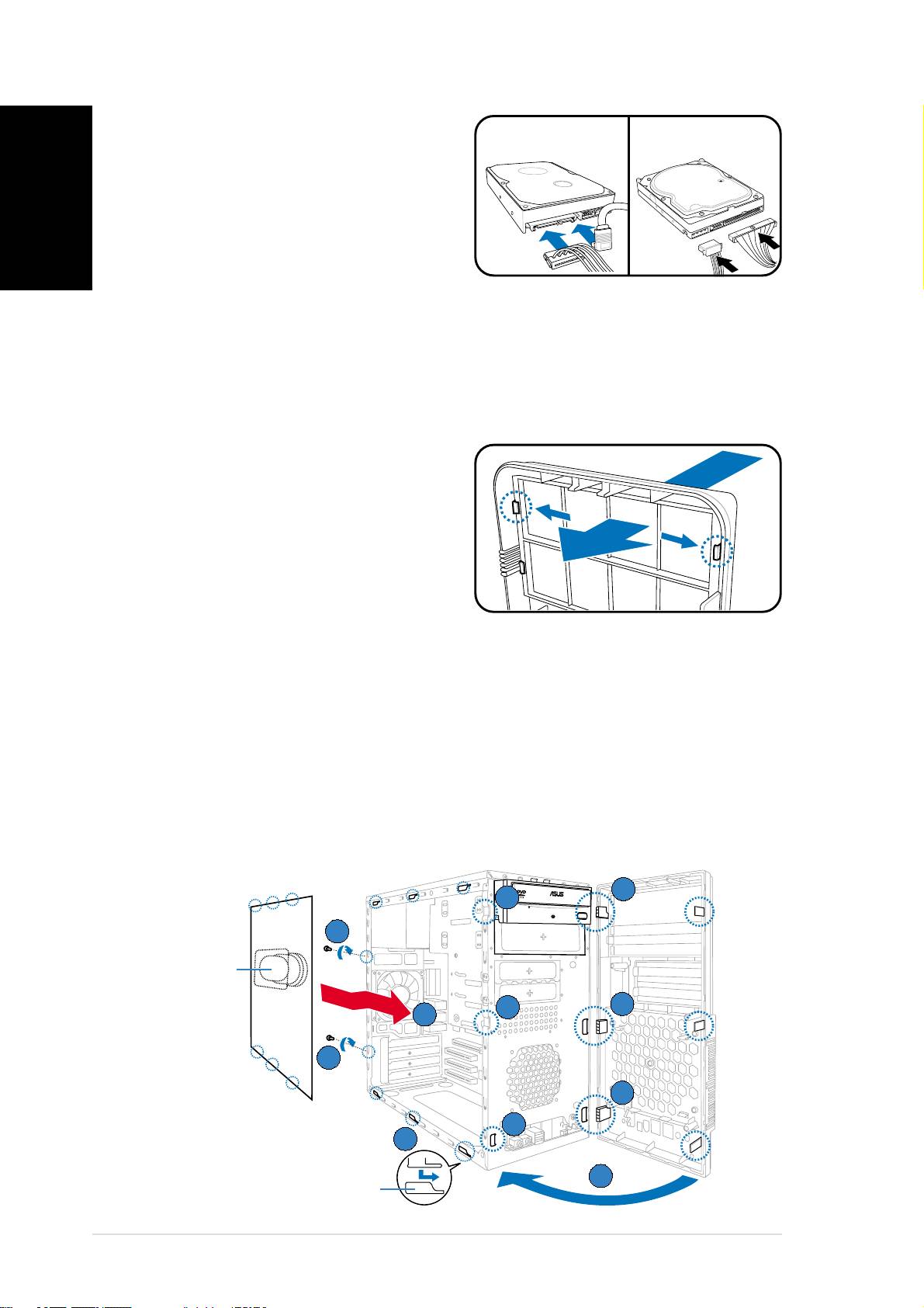
4.
For SATA HDDFor SATA HDD
For SATA HDDFor SATA HDD
For SATA HDD: Connect the
SATASATA
SATASATA
SATA
IDEIDE
IDEIDE
IDE
English
SATA signal and power plugs to
the connectors at the back of
the drive.
For IDE HDDFor IDE HDD
For IDE HDDFor IDE HDD
For IDE HDD: Connect the IDE
and power plugs to the connectors
at the back of the drive.
Removing the bay covers and reinstalling
the front panel assembly and side cover
If you installed an optical and/or floppy disk drive, remove the bay cover(s)
on the front panel assembly before reinstalling it to the chassis. To do this:
1. Locate the bay cover locks.
2. Press the locks outward to
release the bay cover.
3. Push the bay cover inward, then
set it aside.
4. Follow the same instructions to
remove the 3.5” drive bay cover.
To reinstall the front panel assembly and side cover:
1. Insert the front panel assembly hinge-like tabs to the holes on the
right side of the chassis.
2. Swing the front panel assembly to the left, then insert the hooks to
the chassis until the front panel assembly fits in place.
3. Insert the six side cover hooks into the chassis tab holes .
4. Push the side cover to the direction of the front panel until it fits in place.
5. Secure the cover with two screws you removed earlier.
1
11
11
22
22
2
55
55
5
Air ductAir duct
Air ductAir duct
Air duct
22
22
2
11
11
1
44
44
4
55
55
5
11
11
1
22
22
2
33
33
3
22
22
2
Chassis tab holesChassis tab holes
Chassis tab holesChassis tab holes
Chassis tab holes
1010
1010
10
Quick installation guideQuick installation guide
Quick installation guideQuick installation guide
Quick installation guide
