Asus V2-AE1: инструкция
Раздел: Бытовая, кухонная техника, электроника и оборудование
Тип: Компьютер
Инструкция к Компьютеру Asus V2-AE1
English
Vintage2-AE1
Barebone System
Quick Installation Guide
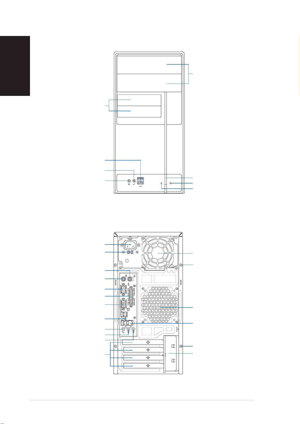
Front panel features
English
5.25-inch drive5.25-inch drive
5.25-inch drive5.25-inch drive
5.25-inch drive
bay coverbay cover
bay coverbay cover
bay cover
3.5-inch drive bay3.5-inch drive bay
3.5-inch drive bay3.5-inch drive bay
3.5-inch drive bay
covercover
covercover
cover
USB 2.0 portsUSB 2.0 ports
USB 2.0 portsUSB 2.0 ports
USB 2.0 ports
Microphone portMicrophone port
Microphone portMicrophone port
Microphone port
Power buttonPower button
Power buttonPower button
Power button
Headphone portHeadphone port
Headphone portHeadphone port
Headphone port
Reset buttonReset button
Reset buttonReset button
Reset button
HDD LEDHDD LED
HDD LEDHDD LED
HDD LED
Rear panel features
Power connectorPower connector
Power connectorPower connector
Power connector
Voltage selectorVoltage selector
Voltage selectorVoltage selector
Voltage selector
Power supply fanPower supply fan
Power supply fanPower supply fan
Power supply fan
Cover screwCover screw
Cover screwCover screw
Cover screw
PS/2 mouse portPS/2 mouse port
PS/2 mouse portPS/2 mouse port
PS/2 mouse port
PS/2 keyboard portPS/2 keyboard port
PS/2 keyboard portPS/2 keyboard port
PS/2 keyboard port
Serial portSerial port
Serial portSerial port
Serial port
Parallel portParallel port
Parallel portParallel port
Parallel port
VGA port VGA port
VGA port VGA port
VGA port
Chassis fan ventsChassis fan vents
Chassis fan ventsChassis fan vents
Chassis fan vents
USB 2.0 portsUSB 2.0 ports
USB 2.0 portsUSB 2.0 ports
USB 2.0 ports
LAN (RJ-45) portLAN (RJ-45) port
LAN (RJ-45) portLAN (RJ-45) port
LAN (RJ-45) port
Microphone portMicrophone port
Microphone portMicrophone port
Microphone port
Line Out portLine Out port
Line Out portLine Out port
Line Out port
Line In portLine In port
Line In portLine In port
Line In port
Cover screwCover screw
Cover screwCover screw
Cover screw
Expansion slotExpansion slot
Expansion slotExpansion slot
Expansion slot
Metal bracket lockMetal bracket lock
Metal bracket lockMetal bracket lock
Metal bracket lock
metal bracketsmetal brackets
metal bracketsmetal brackets
metal brackets
22
22
2
Quick installation guideQuick installation guide
Quick installation guideQuick installation guide
Quick installation guide
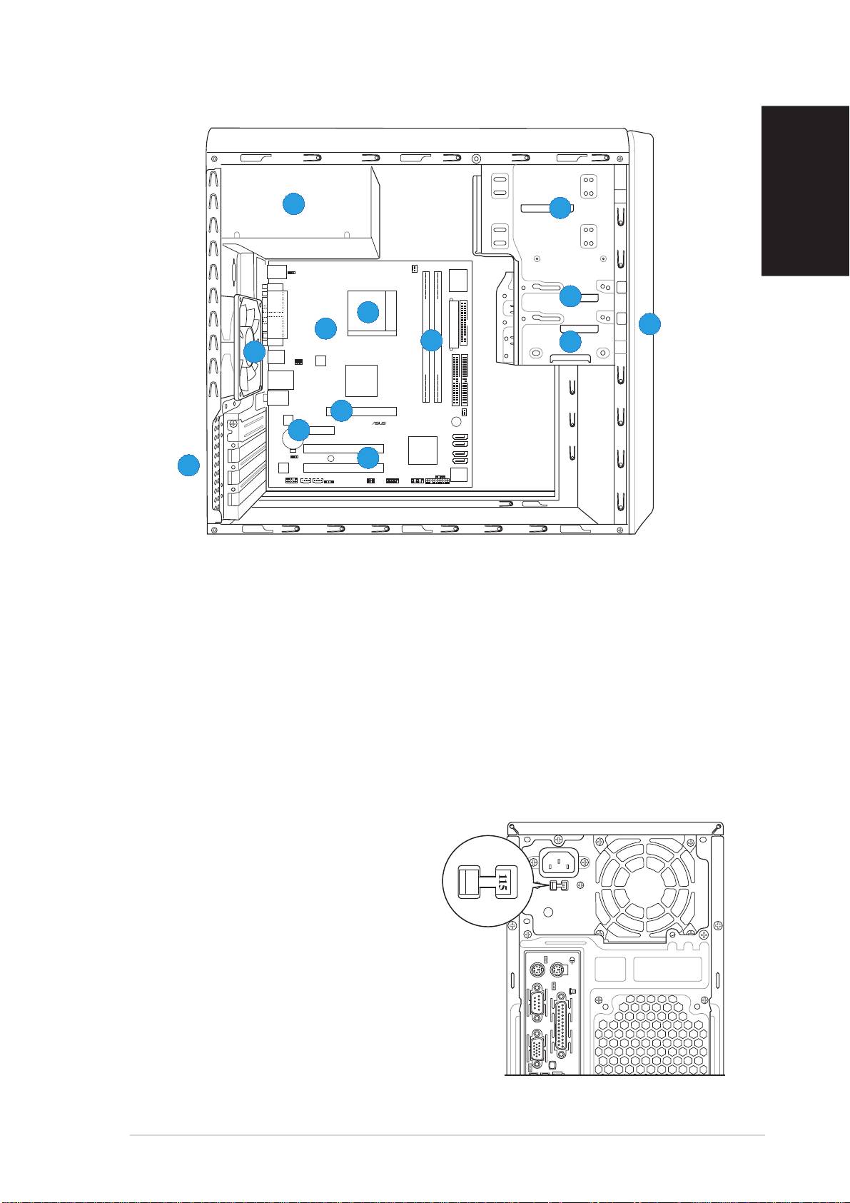
Internal components
55
55
5
22
22
2
English
PS/2KBMS
T: Mouse
KBPWR
B: Keyboard
CPU_FAN
Super
I/O
COM1
33
33
3
66
66
6
PARALLEL PORT
Socket 939
11
11
1
88
88
8
EATXPWR
VGA
77
77
7
FLOPPY
44
44
4
99
99
9
USB12
USBPW12
USBPW34
ATX12V
DDR DIMM_A1 (64 bit,184-pin module)
DDR DIMM_B1 (64 bit,184-pin module)
LAN_USB34
VIA
K8M800
Top:Line In
Center:Line Out
Below:Mic In
PRI_IDE
SEC_IDE
CHA_FAN
1010
1010
10
AGP
RTL8201CL
PCIEX1
BUZZER
CR2032 3V
11
11
1
11
Lithium Cell
11
1
SATA 2
CMOS Power
A8V-MQ
SATA 1
PCI1
VIA
VT8251
SATA 4
CLRTC
SB_PWR
11
11
1
22
22
2
SATA 3
11
11
1
33
33
3
ALC653
PCI2
CHASSIS
BIOS
PANEL
Flash
FP_AUDIO
AUX CD
SPDIF
USBPW56
USBPW78
ROM
USB56
USB78
1. Front panel cover
8. ASUS motherboard
2. 5.25-inch optical drive bays
9. Chassis fan
3. Hard disk drive bay
10. AGP slot
4. Floppy disk drive bay
11. PCI Express x1 slot
5. Power supply unit
12. PCI slots
6. CPU socket
13. Metal bracket lock
7. DIMM sockets
Selecting the voltage
The system’s power supply unit has a
115 V/230 V voltage selector switch
located beside the power connector.
Use this switch to select the
appropriate system input voltage
according to the voltage supply in your
area.
If the voltage supply in your area is
100-127 V, set the switch to 115 V.
If the voltage supply in your area is
200-240 V, set the switch to 230 V.
Quick installation guideQuick installation guide
Quick installation guideQuick installation guide
Quick installation guide
33
33
3
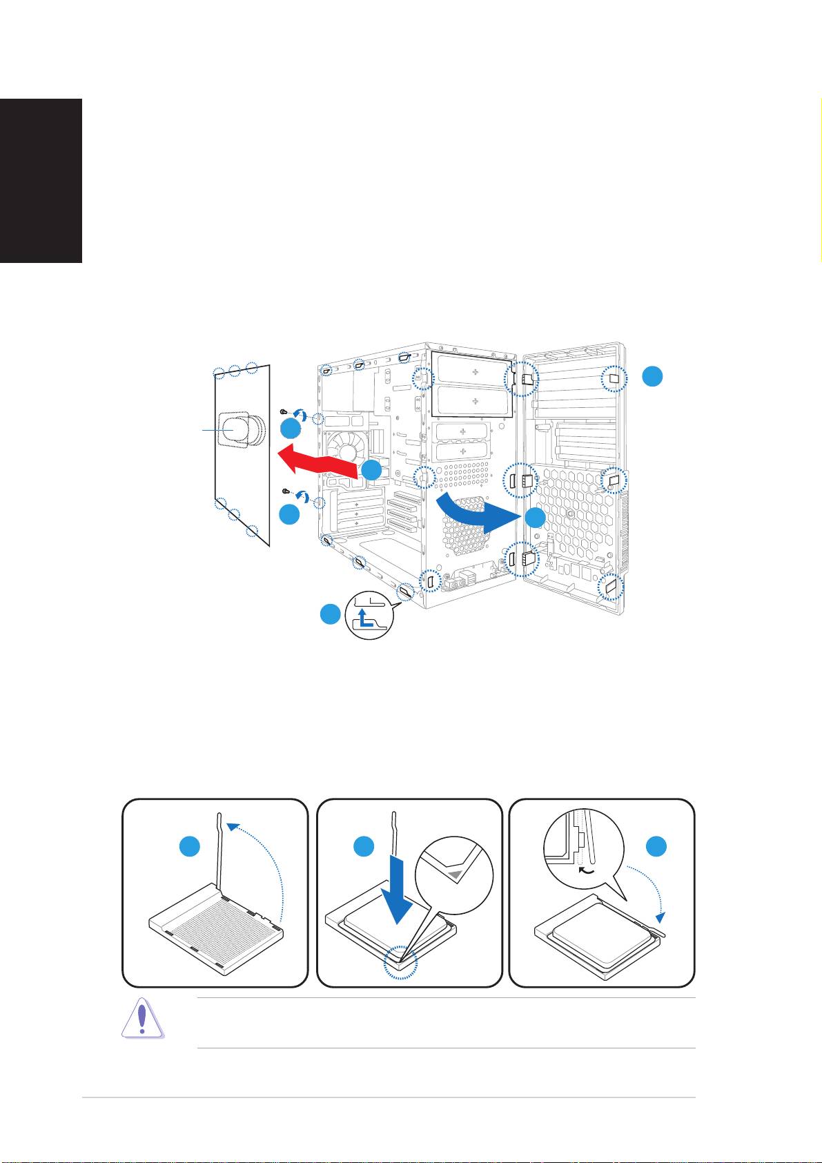
Removing the side cover and
front panel assembly
English
1. Remove the cover screws on the rear panel.
2. Pull the side cover toward the rear panel until its hooks disengage
from the chassis tabs. Set the side cover aside.
3. Locate the front panel assembly hooks, then lift them until they
disengage from the chassis.
4. Swing the front panel assembly to the right, until the hinge-like tabs
on the right side of the assembly are exposed.
5. Remove the front panel assembly, then set aside.
33
33
3
Air ductAir duct
Air ductAir duct
Air duct
11
11
1
22
22
2
1
11
11
44
44
4
2
22
22
Installing a CPU
1. Locate the CPU socket, then lift the socket lever to a 90º-100º angle.
2. Install the CPU to the socket, making sure that the CPU corner with
the gold triangle matches the socket corner with a small triangle.
3. Push down the socket lever to secure the CPU.
11
11
1
22
22
2
33
33
3
CAUTION: CAUTION:
CAUTION: CAUTION:
CAUTION: Incorrect installation of the CPU into the socket may bend
the pins and severely damage the CPU!
44
44
4
Quick installation guideQuick installation guide
Quick installation guideQuick installation guide
Quick installation guide
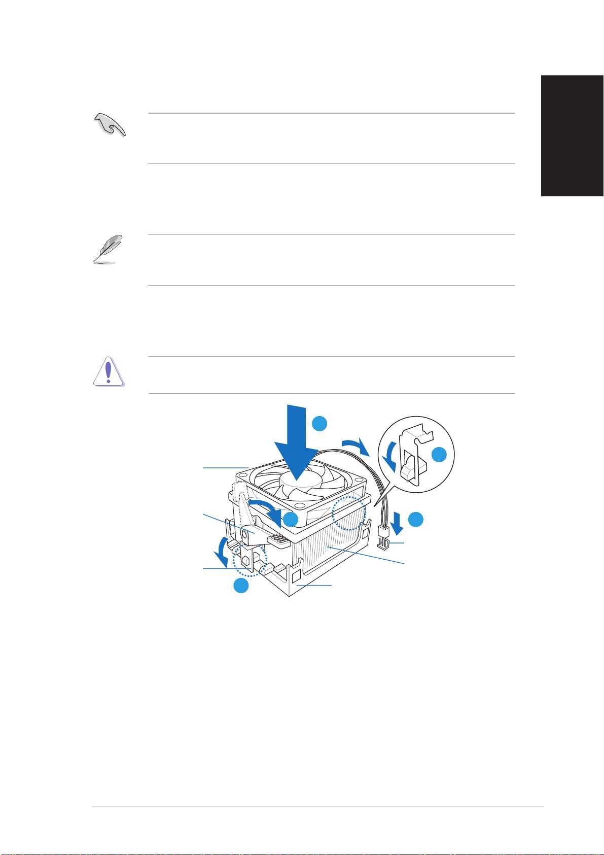
Installing the CPU fan and heatsink assembly
1. Place the heatsink on top of the installed CPU.
IMPORTANTIMPORTANT
IMPORTANTIMPORTANT
IMPORTANT. Make sure that the fan and heatsink assembly perfectly fits
the retention mechanism module base; otherwise you can not lock the
retention bracket.
English
2. Attach one end of the retention bracket to the retention module base.
3. Attach the other end of the retention bracket (near the retention
bracket lock) to the retention module base until it clicks in place.
NOTENOTE
NOTENOTE
NOTE. Your boxed CPU should come with installation instructions for the
CPU, fan/heatsink assembly, and the retention mechanism. If the instructions
in this section do not match the CPU documentation, follow the latter.
4. Push down the retention bracket lock on the retention mechanism to
secure the fan and heatsink to the module retention module base.
5. Connect the CPU fan cable to the connector on the motherboard.
CAUTIONCAUTION
CAUTIONCAUTION
CAUTION. Do not forget to connect the CPU fan connector! Hardware
monitoring error can occur if you fail to plug this connector.
11
11
1
22
22
2
CPU fanCPU fan
CPU fanCPU fan
CPU fan
RetentionRetention
RetentionRetention
Retention
bracket lock
bracket lockbracket lock
bracket lockbracket lock
44
44
4
55
55
5
CPU fan connectorCPU fan connector
CPU fan connectorCPU fan connector
CPU fan connector
CPU heatsinkCPU heatsink
CPU heatsinkCPU heatsink
CPU heatsink
Retention bracketRetention bracket
Retention bracketRetention bracket
Retention bracket
33
33
3
Retention module baseRetention module base
Retention module baseRetention module base
Retention module base
Quick installation guideQuick installation guide
Quick installation guideQuick installation guide
Quick installation guide
55
55
5
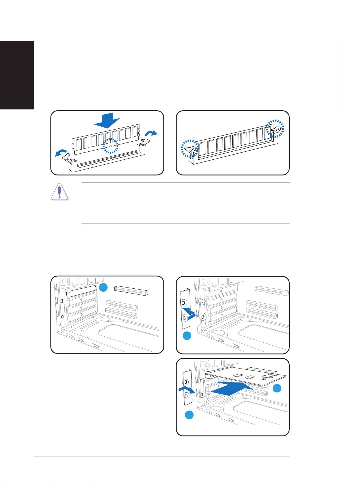
Installing a DIMM
English
1. Locate the DIMM sockets in the motherboard.
2. Unlock a DIMM socket by pressing the retaining clips outward.
3. Align a DIMM on the socket such that the notch on the DIMM matches
the break on the socket.
4. Push the DIMM to the socket until the retaining clips snap inward.
• Unplug the power supply before adding or removing DIMMs. Failure to
do so may cause damage to the motherboard and/or components.
• A DDR DIMM is keyed with a notch so that it fits in only one direction.
Do not force a DIMM into a socket to avoid damaging the DIMM.
Installing an expansion card
1. Remove the metal cover
2. Remove the metal bracket
opposite the slot that you
lock.
intend to use.
11
11
1
22
22
2
3. Insert the card connector to
the slot, then press the card
firmly until it fits in place.
33
33
3
4. Replace the metal bracket
lock.
44
44
4
66
66
6
Quick installation guideQuick installation guide
Quick installation guideQuick installation guide
Quick installation guide
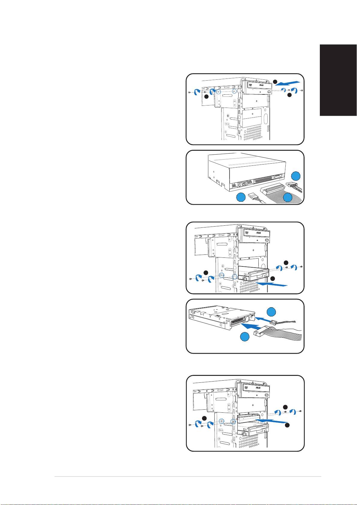
Installing storage drives
Optical drive
Optical driveOptical drive
Optical driveOptical drive
1. Place the chassis upright, then
2
remove the upper 5.25” drive
bay metal plate cover.
3
3
English
2. Insert the optical drive to the
bay, then carefully push the
drive until its screw holes align
with the holes on the bay.
3. Secure the optical drive with two
screws on both sides of the bay.
4. Connect the audio (A), IDE (B),
and power (C) plugs to
CC
CC
C
connectors at the back of the
drive.
AA
AA
A
BB
BB
B
Floppy disk drive
Floppy disk driveFloppy disk drive
Floppy disk driveFloppy disk drive
1. Place the chassis upright, then
remove the lower 3.5” drive bay
metal plate cover.
2. Insert the floppy disk drive to
3
the bay, then carefully push the
3
drive until its screw holes align
2
with the holes on the bay.
3. Secure the floppy disk drive with
two screws on both sides of the
bay.
BB
BB
B
4. Connect the signal (A) and
power (B) plugs to connectors
AA
AA
A
at the back of the drive.
Hard disk drive
Hard disk driveHard disk drive
Hard disk driveHard disk drive
1. Place the chassis upright, then
remove the upper 3.5” drive bay
metal plate cover.
3
2. Insert the hard disk drive to the
bay, then carefully push the
3
2
drive until its screw holes align
with the holes on the bay.
3. Secure the hard disk drive with
two screws on both sides of the
bay.
Quick installation guideQuick installation guide
Quick installation guideQuick installation guide
Quick installation guide
77
77
7
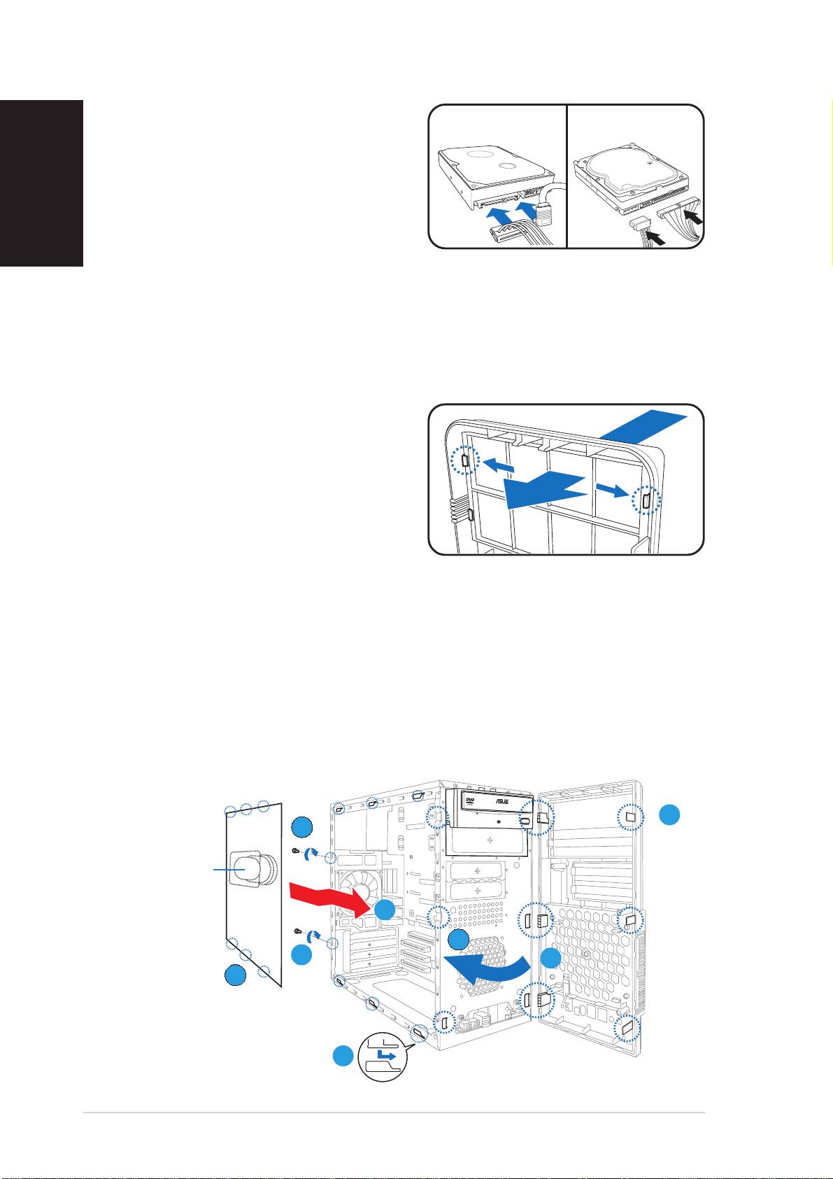
4.
For SATA HDDFor SATA HDD
For SATA HDDFor SATA HDD
For SATA HDD: Connect the
SATASATA
SATASATA
SATA
IDEIDE
IDEIDE
IDE
SATA signal and power plugs to
English
the connectors at the back of
the drive.
For IDE HDDFor IDE HDD
For IDE HDDFor IDE HDD
For IDE HDD: Connect the IDE
and power plugs to the connectors
at the back of the drive.
Removing the bay covers and reinstalling
the front panel assembly and side cover
If you installed an optical and/or floppy disk drive, remove the bay cover(s)
on the front panel assembly before reinstalling it to the chassis. To do this:
1. Locate the bay cover locks.
2. Press the locks outward to
release the bay cover.
3. Push the bay cover inward, then
set it aside.
4. Follow the same instructions to
remove the 3.5” drive bay cover.
To reinstall the front panel assembly and side cover:
1. Insert the front panel assembly hinge-like tabs to the holes on the
right side of the chassis.
2. Swing the front panel assembly to the left, then insert the hooks to
the chassis until the front panel assembly fits in place.
3. Insert the side cover hooks to the chassis top and bottom holes.
4. Push the side cover to the direction of the front panel until it fits in place.
5. Secure the cover with two screws you removed earlier.
2
22
22
55
55
5
Air ductAir duct
Air ductAir duct
Air duct
44
44
4
22
22
2
5
55
55
11
11
1
33
33
3
33
33
3
88
88
8
Quick installation guideQuick installation guide
Quick installation guideQuick installation guide
Quick installation guide
