Asus A7V8X: Chapter 4
Chapter 4: Asus A7V8X
Chapter 4
This chapter tells how to change system
settings through the BIOS Setup menus.
Detailed descriptions of the BIOS
parameters are also provided.
BIOS setup

Chapter summary
4.1 Managing and updating your BIOS .............. 4-1
4.2 BIOS Setup program...................................... 4-7
4.3 Main Menu .................................................... 4-10
4.4 Advanced Menu ........................................... 4-17
4.5 Power Menu.................................................. 4-27
4.6 Boot Menu .................................................... 4-33
4.7 Exit Menu ...................................................... 4-35
ASUS A7V8X motherboard

4.1 Managing and updating your BIOS
It is recommended that you save a copy of the motherboard’s original
BIOS to a bootable floppy disk in case you need to reinstall the original
BIOS later.
4.1.1 Using ASUS EZ Flash to update the BIOS
The ASUS EZ Flash feature allows you to easily update the BIOS without
having to go through the long process of booting from a diskette and using
a DOS-based utility. The EZ Flash is built-in the BIOS firmware so it is
accessible by simply pressing <Alt> + <F2> during the Power-On Self
Tests (POST).
Follow these steps to update the BIOS using ASUS EZ Flash.
1. Download the latest BIOS file from the ASUS website (see ASUS
contact information on page x). Save the file to a floppy disk.
Write down the BIOS file name on a piece of paper. You need to type
the exact BIOS file name at the EZ Flash screen.
2. Reboot the computer.
3. To use EZ Flash, press <Alt> + <F2> during POST to display the
following screen.
ASUS EZ Flash V1.00
Copyright (C) 2002, ASUSTeK COMPUTER INC.
[Onboard BIOS Information]
BIOS Version : ASUS A7V8X ACPI BIOS Revision 1001 Beta 003
BIOS Model : A7V8X
BIOS Built Date : 07/29/02
Please Enter File Name for NEW BIOS: _
*Note: EZ Flash will copy file from A:\, Press [ESC] to reboot
The BIOS information in the above screen is for reference only. What
you see on your screen may not be exactly the same as shown.
4. Insert the disk that contains the new BIOS file into the floppy drive. You
will receive the error message,
“WARNING! Device not ready.” if you
proceed to step 5 without the disk in the drive.
ASUS A7V8X motherboard user guide
4-1
5. At the prompt, “Please Enter File Name for NEW BIOS: _”, type in the
BIOS file name that you downloaded from the ASUS website, then
press <Enter>.
EZ Flash will automatically access drive A to look for the file name that
you typed. When found, the following message appears on screen.
[BIOS Information in File]
BIOS Version: A7V8X Boot Block
WARNING! Continue to update the BIOS (Y/N)? _
If you accidentally typed in a wrong BIOS file name, the error
message, “WARNING! File not found.” appears. Press <Enter> to
remove the message, then type in the correct file name. Press
<Enter>.
6. At the above prompt, type
Y to continue with the update process.
Pressing N exits the EZ Flash screen and reboots the system without
updating the BIOS.
The following prompts appear if you typed
Y.
Flash Memory: SST 49LF004
1. Update Main BIOS area (Y/N)? _
2. Update Boot Block area (Y/N)? _
7. Press
Y for both items to completely update the main BIOS area and
the boot block area.
DO NOT shutdown or reset the system while updating the BIOS boot
block area! Doing so may cause system boot failure.
8. When the update process is done, the message, “Press a key to
reboot”
appears. Press any key to reboot the system with the new
BIOS.
4-2
Chapter 4: BIOS Setup
4.1.2 Using AFLASH to update the BIOS
Creating a bootable disk
AFLASH.EXE is a Flash Memory Writer utility that updates the BIOS by
uploading a new BIOS file to the programmable flash ROM on the
motherboard. This file works only in DOS mode. To determine the BIOS
version of your motherboard, check the last four numbers of the code
displayed on the upper left-hand corner of your screen during bootup.
Larger numbers represent a newer BIOS file.
1. Type FORMAT A:/S at the DOS prompt to create a bootable system
disk. DO NOT copy AUTOEXEC.BAT and CONFIG.SYS to the disk.
2. Type COPY D:\AFLASH\AFLASH.EXE A:\ (assuming D is your
CD-ROM drive) to copy AFLASH.EXE to the boot disk you created.
AFLASH works only in DOS mode. It does not work in the DOS prompt
within Windows, and does not work with certain memory drivers that
may be loaded when you boot from the hard drive. It is recommended
that you reboot using a floppy disk.
3. Reboot the computer from the floppy disk.
BIOS setup must specify “Floppy” as the first item in the boot
sequence.
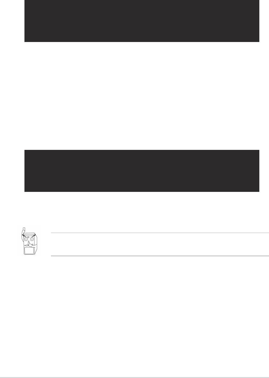
4. In DOS mode, type A:\AFLASH <Enter> to run AFLASH.
If the word “unknown” appears after Flash Memory:, the memory chip
is either not programmable or is not supported by the ACPI BIOS and
therefore, cannot be programmed by the Flash Memory Writer utility.
ASUS A7V8X motherboard user guide
4-3

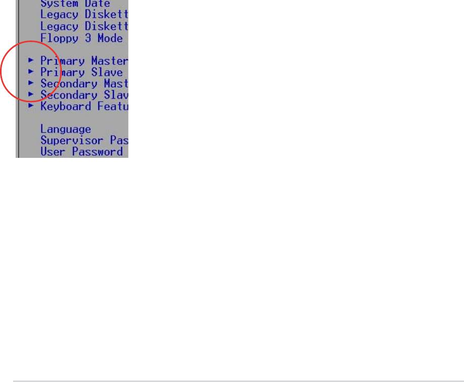
5. Select 1. Save Current BIOS to File from the Main menu and press
<Enter>. The Save Current BIOS To File screen appears.
6. Type a filename and the path, for example, A:\XXX-XX.XXX, then
press <Enter>.
4-4
Chapter 4: BIOS Setup
Updating the BIOS
Update the BIOS only if you have problems with the motherboard and
you are sure that the new BIOS revision will solve your problems.
Careless updating may result to more problems with the motherboard!
1. Download an updated ASUS BIOS file from the Internet (WWW or
FTP) (see ASUS CONTACT INFORMATION on page x for details) and
save to the boot floppy disk you created earlier.
2. Boot from the floppy disk.
3. At the “A:\” prompt, type AFLASH and then press <Enter>.
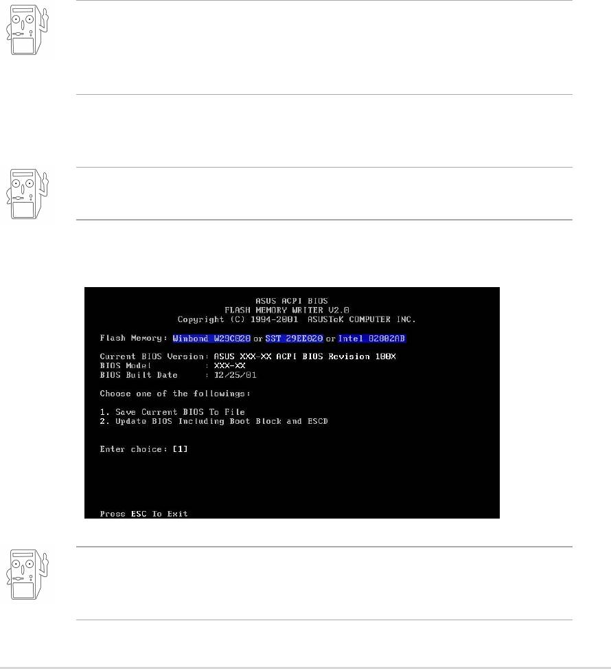
4. At the Main Menu, type 2 then press <Enter>. The Update BIOS
Including Boot Block and ESCD screen appears.
5. Type the filename of your new BIOS and the path, for example,
A:\XXX-XX.XXX, then press <Enter>.
To cancel this operation, press <Enter>.
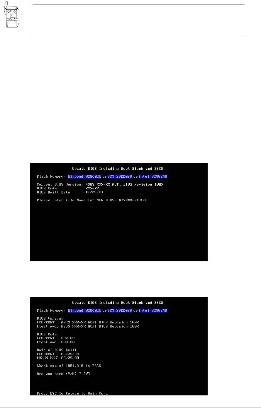
6. When prompted to confirm the BIOS update, press Y to start the
update.
ASUS A7V8X motherboard user guide
4-5
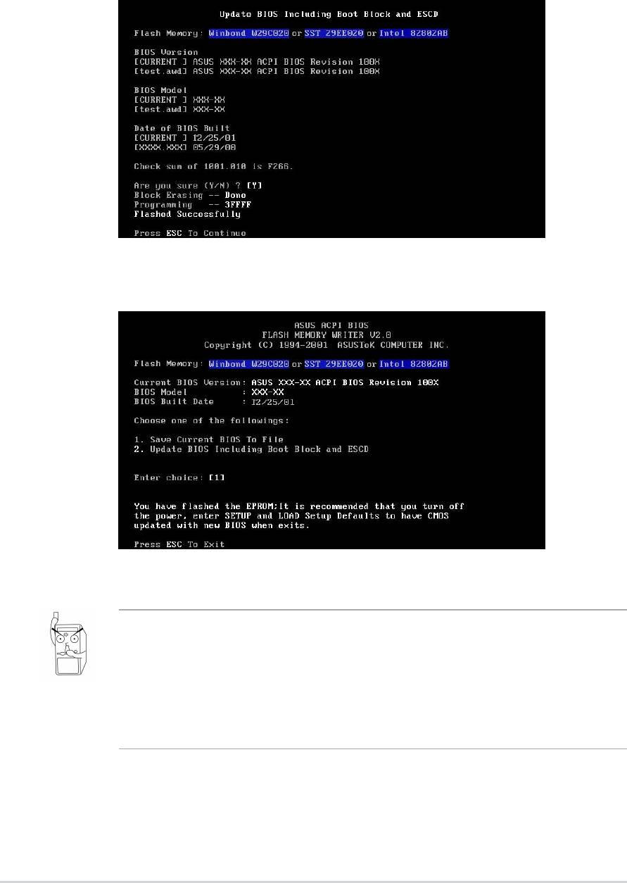
7. The utility starts to program the new BIOS information into the Flash
ROM. The boot block is updated automatically only when necessary.
This minimizes the possibility of boot problems in case of update
failures. When the programming is done, the message “Flashed
Successfully” appears.
8. Follow the onscreen instructions to continue.
If you encounter problems while updating the new BIOS, DO NOT turn
off the system because this may cause boot problems. Just repeat the
process, and if the problem persists, load the original BIOS file you
saved to the boot disk. If the Flash Memory Writer utility is not able to
successfully update a complete BIOS file, the system may not boot. If
this happens, call the ASUS service center for support.
4-6
Chapter 4: BIOS Setup

4.2 BIOS Setup program
This motherboard supports a programmable Flash ROM that you can
update using the provided utility described in section “4.1 Managing and
updating your BIOS.”
Use the BIOS Setup program when you are installing a motherboard,
reconfiguring your system, or prompted to “Run Setup”. This section
explains how to configure your system using this utility.
Even if you are not prompted to use the Setup program, you may want to
change the configuration of your computer in the future. For example, you
may want to enable the security password feature or make changes to the
power management settings. This requires you to reconfigure your system
using the BIOS Setup program so that the computer can recognize these
changes and record them in the CMOS RAM of the Flash ROM.
The Flash ROM on the motherboard stores the Setup utility. When you
start up the computer, the system provides you with the opportunity to run
this program. Press <Delete> during the Power-On Self Test (POST) to
enter the Setup utility, otherwise, POST continues with its test routines.
If you wish to enter Setup after POST, restart the system by pressing
<Ctrl> + <Alt> + <Delete>, or by pressing the reset button on the system
chassis. You can also restart by turning the system off and then back on.
Do this last option only if the first two failed.
The Setup program is designed to make it as easy to use as possible. It is
a menu-driven program, which means you can scroll through the various
sub-menus and make your selections among the predetermined choices.
Because the BIOS software is constantly being updated, the following
BIOS setup screens and descriptions are for reference purposes only,
and may not exactly match what you see on your screen.
ASUS A7V8X motherboard user guide
4-7

4.2.1 BIOS menu bar
The top of the screen has a menu bar with the following selections:
MAIN Use this menu to make changes to the basic system
configuration.
ADVANCED Use this menu to enable and make changes to the
advanced features.
POWER Use this menu to configure and enable Power
Management features.
BOOT Use this menu to configure the default system device
used to locate and load the Operating System.
EXIT Use this menu to exit the current menu or to exit the
Setup program.
To access the menu bar items, press the right or left arrow key on the
keyboard until the desired item is highlighted.
4.2.2 Legend bar
At the bottom of the Setup screen is a legend bar. The keys in the legend
bar allow you to navigate through the various setup menus. The following
table lists the keys found in the legend bar with their corresponding
functions.
Navigation Key(s) Function Description
<F1> or <Alt + H> Displays the General Help screen from any-
where in the BIOS Setup
<Esc> Jumps to the Exit menu or returns to the main
menu from a sub-menu
Left or Right arrow Selects the menu item to the left or right
Up or Down arrow Moves the highlight up or down between fields
- (minus key) Scrolls backward through the values for the
highlighted field
+ (plus key) or spacebar Scrolls forward through the values for the high-
lighted field
<Enter> Brings up a selection menu for the highlighted
field
<Home> or <PgUp> Moves the cursor to the first field
<End> or <PgDn> Moves the cursor to the last field
<F5> Resets the current screen to its Setup Defaults
<F10> Saves changes and exits Setup
4-8
Chapter 4: BIOS Setup
General help
In addition to the Item Specific Help window, the BIOS setup program also
provides a General Help screen. You may launch this screen from any
menu by simply pressing <F1> or the <Alt> + <H> combination. The
General Help screen lists the legend keys and their corresponding
functions.
Saving changes and exiting the Setup program
See “4.7 Exit Menu” for detailed information on saving changes and exiting
the setup program.
Scroll bar
When a scroll bar appears to the right of a help window, it indicates that
there is more information to be displayed that will not fit in the window. Use
<PgUp> and <PgDn> or the up and down arrow keys to scroll through the
entire help document. Press <Home> to display the first page, press
<End> to go to the last page. To exit the help window, press <Enter> or
<Esc>.
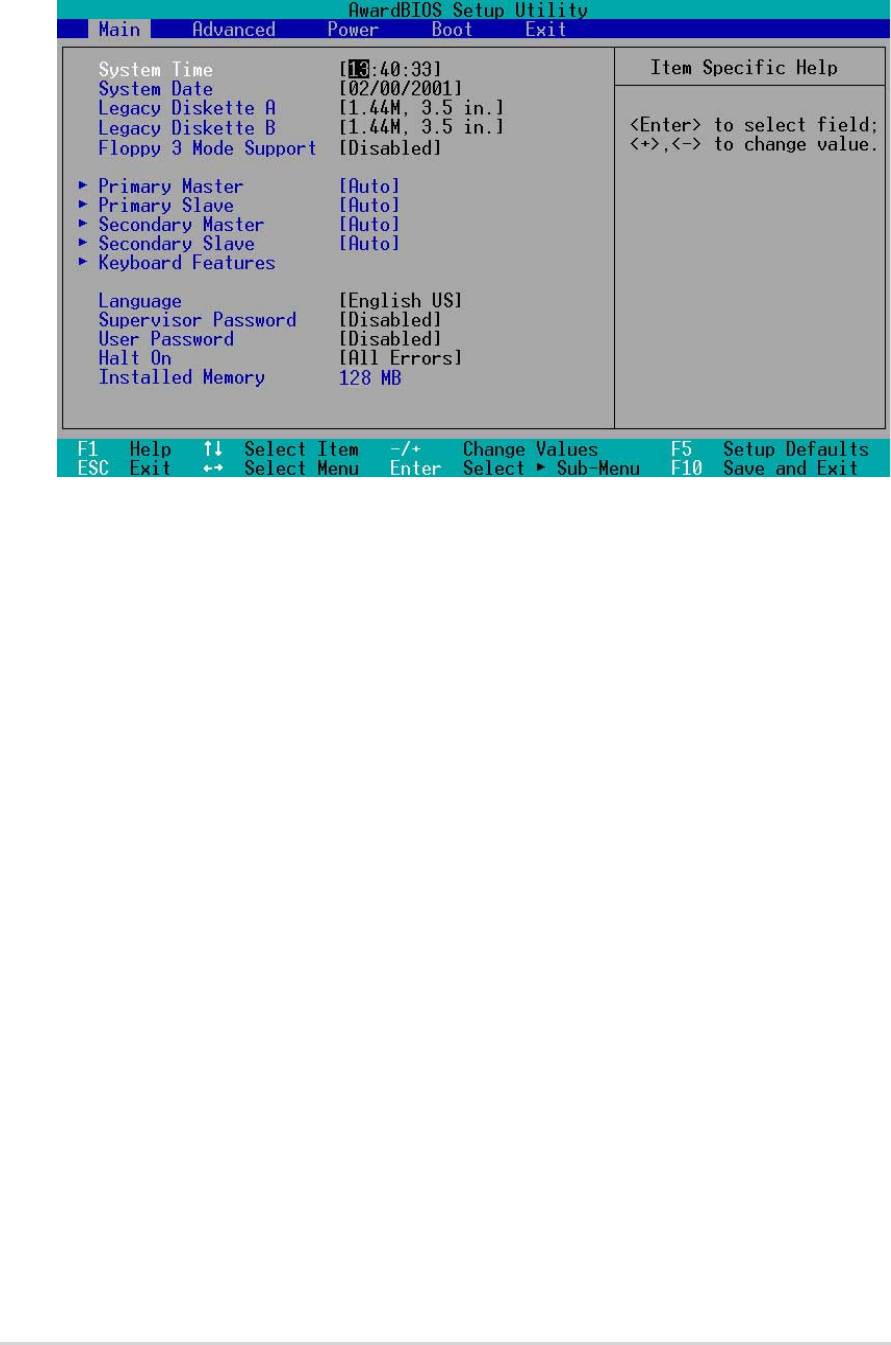
Sub-menu
Note that a right pointer symbol (as shown on the
left) appears to the left of certain fields. This pointer
indicates that you can display a sub-menu from this
field. A sub-menu contains additional options for a
field parameter. To display a sub-menu, move the
highlight to the field and press <Enter>. The sub-
menu appears. Use the legend keys to enter values
and move from field to field within a sub-menu as
you would within a menu. Use the <Esc> key to
return to the main menu.
Take some time to familiarize yourself with the legend keys and their
corresponding functions. Practice navigating through the various menus
and sub-menus. If you accidentally make unwanted changes to any of the
fields, use the set default hot key <F5> to load the Setup default values.
While moving around through the Setup program, note that explanations
appear in the Item Specific Help window located to the right of each menu.
This window displays the help text for the currently highlighted field.
ASUS A7V8X motherboard user guide
4-9
4.3 Main Menu
When you enter the Setup program, the following screen appears.
System Time [XX:XX:XX]
Sets the system to the time that you specify (usually the current time). The
format is hour, minute, second. Valid values for hour, minute and second
are Hour: (00 to 23), Minute: (00 to 59), Second: (00 to 59). Use the <Tab>
or <Shift> + <Tab> keys to move between the hour, minute, and second
fields.
System Date [XX/XX/XXXX]
Sets the system to the date that you specify (usually the current date). The
format is month, day, year. Valid values for month, day, and year are
Month: (1 to 12), Day: (1 to 31), Year: (up to 2099). Use the <Tab> or
<Shift> + <Tab> keys to move between the month, day, and year fields.
Legacy Diskette A [1.44M, 3.5 in.];
Legacy Diskette B [1.44M, 3.5 in.]
Sets the type of floppy drive installed. Configuration options: [None] [360K,
5.25 in.] [1.2M , 5.25 in.] [720K , 3.5 in.] [1.44M, 3.5 in.] [2.88M, 3.5 in.]
Floppy 3 Mode Support [Disabled]
This is required to support older Japanese floppy drives. The Floppy 3
Mode feature allows reading and writing of 1.2MB (as opposed to 1.44MB)
on a 3.5-inch diskette. Configuration options: [Disabled] [Enabled]
4-10
Chapter 4: BIOS Setup

Language [English US]
This field allows you to choose the BIOS language version from the
available options.
Supervisor Password [Disabled] / User Password [Disabled]
These fields allow you to set passwords. To set a password, highlight the
appropriate field and press <Enter>. Type in a password then press
<Enter>. You can type up to eight alphanumeric characters. Symbols and
other characters are ignored. To confirm the password, type the password
again and press <Enter>. The password is now set to [Enabled]. This
password allows full access to the BIOS Setup menus. To clear the
password, highlight this field and press <Enter>. The same dialog box as
above appears. Press <Enter>. The password is set to [Disabled].
A note about passwords
The BIOS Setup program allows you to specify passwords in the Main
menu. The passwords control access to the BIOS during system
startup. Passwords are not case sensitive, meaning, passwords typed
in either uppercase or lowercase letters are accepted. The BIOS Setup
program allows you to specify two different passwords: a Supervisor
password and a User password. If you did not set a Supervisor
password, anyone can access the BIOS Setup program. If you did, the
Supervisor password is required to enter the BIOS Setup program and
to gain full access to the configuration fields.
Forgot the password?
If you forget your password, you can clear it by erasing the CMOS
Real Time Clock (RTC) RAM. The RAM data containing the password
information is powered by the onboard button cell battery. See section
“2.7Switches and jumpers” for information on how to erase the R TC
RAM.
Halt On [All Errors]
This field specifies the types of errors that will cause the system to halt.
Configuration options: [All Errors] [No Error] [All but Keyboard] [All but
Disk] [All but Disk/Keyboard]
Installed Memory [XXX MB]
This field automatically displays the amount of conventional memory
detected by the system during the boot process.
ASUS A7V8X motherboard user guide
4-11
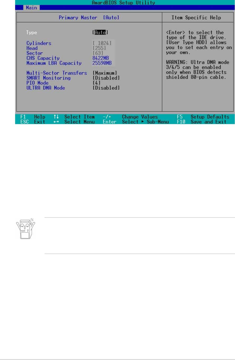
4.3.1 Primary and Secondary Master/Slave
Type [Auto]
Select [Auto] to automatically detect an IDE hard disk drive. If automatic
detection is successful, Setup automatically fills in the correct values for
the remaining fields on this sub-menu. If automatic detection fails, this may
be because the hard disk drive is too old or too new. If the hard disk was
already formatted on an older system, Setup may detect incorrect
parameters. In these cases, select [User Type HDD] to manually enter the
IDE hard disk drive parameters. Refer to the next section for details.
Before attempting to configure a hard disk drive, make sure you have
the correct configuration information supplied by the drive
manufacturer. Incorrect settings may cause the system to fail to
recognize the installed hard disk.
4-12
Chapter 4: BIOS Setup
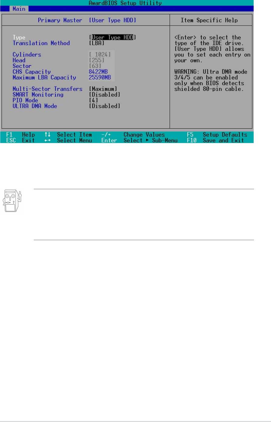
[User Type HDD]
Manually enter the number of cylinders, heads and sectors per track for
the drive. Refer to the drive documentation or on the drive label for this
information.
After entering the IDE hard disk drive information into BIOS, use a disk
utility, such as FDISK, to partition and format new IDE hard disk drives.
This is necessary so that you can write or read data from the hard disk.
Make sure to set the partition of the Primary IDE hard disk drives to
active.
If no drive is installed or if you are removing a drive and not replacing it,
select [None].
Other options for the Type field are:
[CD-ROM] - for IDE CD-ROM drives
[LS-120] - for LS-120 compatible floppy disk drives
[ZIP] - for ZIP-compatible disk drives
[MO] - for IDE magneto optical disk drives
[Other ATAPI Device] - for IDE devices not listed here
After making your selections on this sub-menu, press the <Esc> key to
return to the Main menu. When the Main menu appears, the hard disk
drive field displays the size for the hard disk drive that you configured.
ASUS A7V8X motherboard user guide
4-13

Translation Method [LBA]
Select the hard disk drive type in this field. When Logical Block Addressing
(LBA) is enabled, the 28-bit addressing of the hard drive is used without
regard for cylinders, heads, or sectors. Note that LBA Mode is necessary
for drives with more than 504MB storage capacity. Configuration options:
[LBA] [LARGE] [Normal] [Match Partition Table] [Manual]
Cylinders
This field configures the number of cylinders. Refer to the drive
documentation to determine the correct value. To make changes to this
field, set the Type field to [User Type HDD] and the Translation Method
field to [Manual].
Head
This field configures the number of read/write heads. Refer to the drive
documentation to determine the correct value. To make changes to this
field, set the Type field to [User Type HDD] and the Translation Method
field to [Manual].
Sector
This field configures the number of sectors per track. Refer to the drive
documentation to determine the correct value. To make changes to this
field, set the Type field to [User Type HDD] and the Translation Method
field to [Manual].
CHS Capacity
This field shows the drive’s maximum CHS capacity as calculated by the
BIOS based on the drive information you entered.
Maximum LBA Capacity
This field shows the drive’s maximum LBA capacity as calculated by the
BIOS based on the drive information you entered.
4-14
Chapter 4: BIOS Setup

Multi-Sector Transfers [Maximum]
This option automatically sets the number of sectors per block to the
highest number that the drive supports. Note that when this field is
automatically configured, the set value may not always be the fastest
value for the drive. You may also manually configure this field. Refer to the
documentation that came with the hard drive to determine the optimum
value and set it manually. To make changes to this field, set the Type field
to [User Type HDD]. Configuration options: [Disabled] [2 Sectors] [4
Sectors] [8 Sectors] [16 Sectors] [32 Sectors] [Maximum]
SMART Monitoring [Disabled]
This field allows you to enable or disable the S.M.A.R.T. (Self-Monitoring,
Analysis and Reporting Technology) system that utilizes internal hard disk
drive monitoring technology. This parameter is normally disabled because
the resources used in the SMART monitoring feature may decrease
system performance. Configuration options: [Disabled] [Enabled]
PIO Mode [4]
This option lets you set a PIO (Programmed Input/Output) mode for the
IDE device. Modes 0 through 4 provide successive increase in
performance. Configuration options: [0] [1] [2] [3] [4]
Ultra DMA Mode [Disabled]
Ultra DMA capability allows improved transfer speeds and data integrity for
compatible IDE devices. Set to [Disabled] to suppress Ultra DMA
capability. To make changes to this field, set the Type field to [User Type
HDD]. Configuration options: [0] [1] [2] [3] [4] [5] [Disabled]
ASUS A7V8X motherboard user guide
4-15

4.3.2 Keyboard Features
Boot Up NumLock Status [On]
This field enables users to activate the Number Lock function upon system
boot. Configuration options: [Off] [On]
Keyboard Auto-Repeat Rate [6/Sec]
This controls the speed at which the system registers repeated keystrokes.
Options range from 6 to 30 characters per second. Configuration options:
[6/Sec] [8/Sec] [10/Sec] [12/Sec] [15/Sec] [20/Sec] [24/Sec] [30/Sec]
Keyboard Auto-Repeat Delay [1/4 Sec]
This field sets the time interval for displaying the first and second
characters. Configuration options: [1/4 Sec] [1/2 Sec] [3/4 Sec] [1 Sec]
4-16
Chapter 4: BIOS Setup
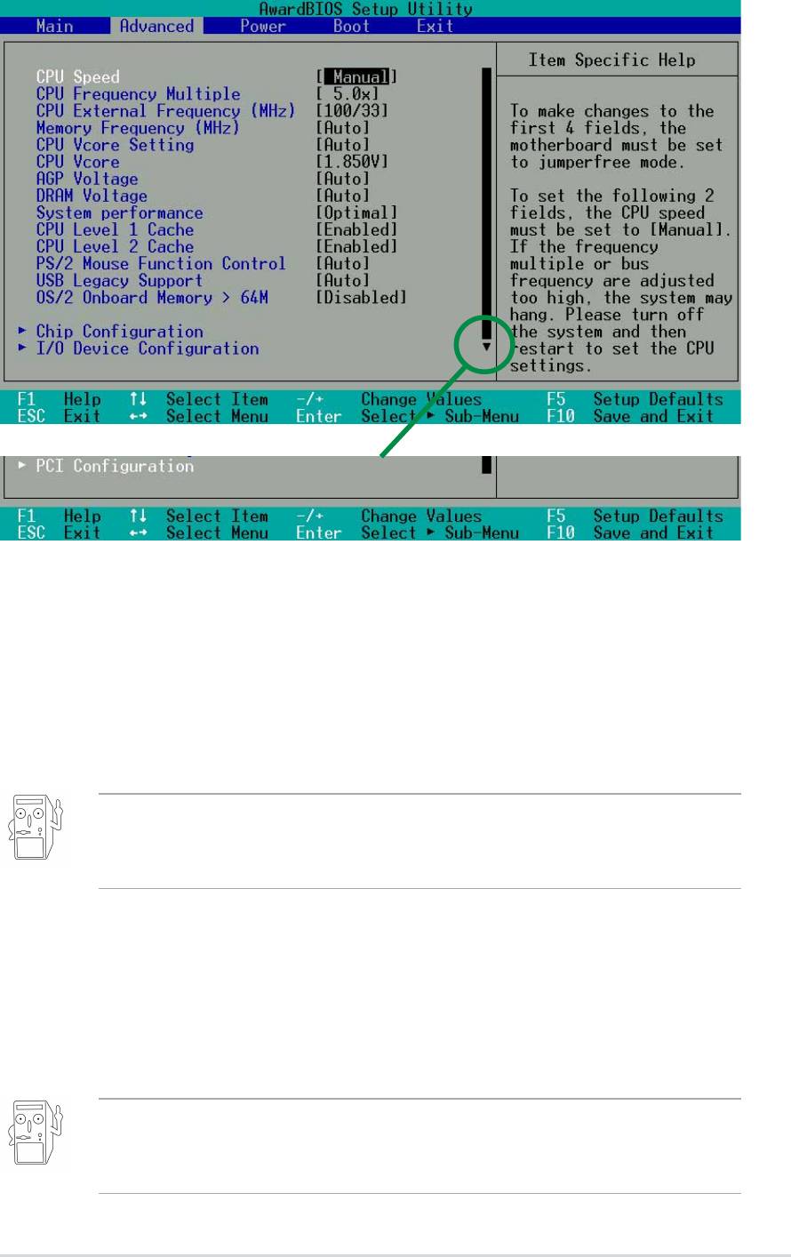
4.4 Advanced Menu
CPU Speed [Manual]
When the motherboard is set to JumperFree™ mode, this field allows you
to select the internal frequency of the CPU. Select [Manual] if you want to
make changes to the two subsequent fields. Note that selecting a
frequency higher than the CPU manufacturer recommends may cause the
system to hang or crash.
System memory can only operate at a frequency higher than or equal
to the CPU front side bus frequency. Refer to Table 1.4.2 “FSB/DDR
Support Table” on page 1-8 for more information.
CPU Frequency Multiple (when CPU Speed is set to [Manual])
This field sets the frequency multiple between the CPU’s internal
frequency (CPU speed) and external frequency. Set this field in
conjunction with CPU Frequency (MHz) to match the speed of the CPU.
The item CPU Frequency Multiple is accessible only if you have an
unlocked processor. If your processor frequency multiple is locked, you
cannot change the setting of this item.
ASUS A7V8X motherboard user guide
4-17

CPU External Frequency (MHz) (when CPU Speed is set to [Manual])
This feature tells the clock generator what frequency to send to the system
bus and PCI bus. The bus frequency (external frequency) multiplied by the
bus multiple equals the CPU speed.
Memory Frequency (Mhz) [Auto]
This field allows you to select a higher memory frequency for better
system performance. The options that appear in the popup menu vary
according to the CPU Frequency (MHz). Configuration options: [Auto]
[200] [266] [333] [400]
CPU VCore Setting [Auto]
The [Manual] setting allows you to manually select the core voltage
supplied to the CPU (see next item). This item can only be changed in
JumperFree mode, otherwise, it is recommended that you keep the default
setting [Auto] to allow the system to automatically determine the
appropriate CPU core voltage.
CPU VCore [1.750V]
When the CPU VCore Setting parameter above is set to [Manual], the
CPU VCore item allows you to select a specific CPU core voltage. This
field is not accessible when the CPU VCore Setting is set to [Auto].
AGP Voltage [Auto]
This item controls the AGP operating voltage. This item can only be
changed at JmpreFree mode, otherwise keep [Auto]. Configuration
options: [1.8V] [1.7V] [1.6V] [1.5V] [Auto]
DRAM Voltage [Auto]
This item controls the DRAM operating voltage. This item can only be
changed at JmpreFree mode, otherwise keep [Auto]. Configuration
options: [Auto] [2.85V] [2.75V] [2.65V] [2.55V]
System Performance [Optimal]
This field allows you to adjust the DRAM SPD timing. Set to [TURBO] is
fastest, just make sure the DRAM has the ability to support it.
Configuration options: [Optimal] [Turbo]
4-18
Chapter 4: BIOS Setup

CPU Level 1 Cache, CPU Level 2 Cache [Enabled]
These fields allow you to choose from the default [Enabled] or choose
[Disabled] to turn on or off the CPU Level 1 and Level 2 built-in cache.
Configuration options: [Disabled] [Enabled]
PS/2 Mouse Function Control [Auto]
The default setting [Auto] allows the system to detect a PS/2 mouse at
startup. If a mouse is detected, the BIOS assigns IRQ12 to the PS/2
mouse. Otherwise, IRQ12 can be used for expansion cards. When you set
this field to [Enabled], BIOS reserves IRQ12, whether or not a PS/2 mouse
is detected at startup. Configuration options: [Enabled] [Auto]
USB Legacy Support [Auto]
This motherboard supports Universal Serial Bus (USB) devices. The
default of [Auto] allows the system to detect a USB device at startup. If
detected, the USB controller legacy mode is enabled. If not detected, the
USB controller legacy mode is disabled.
When you set this field to [Disabled], the USB controller legacy mode is
disabled whether or not you are using a USB device. Configuration
options: [Disabled] [Enabled] [Auto]
OS/2 Onboard Memory > 64M [Disabled]
When using OS/2 operating systems with installed DRAM of greater than
64MB, you need to set this option to [Enabled]. Otherwise, leave to the
default setting [Disabled]. Configuration options: [Disabled] [Enabled]
ASUS A7V8X motherboard user guide
4-19
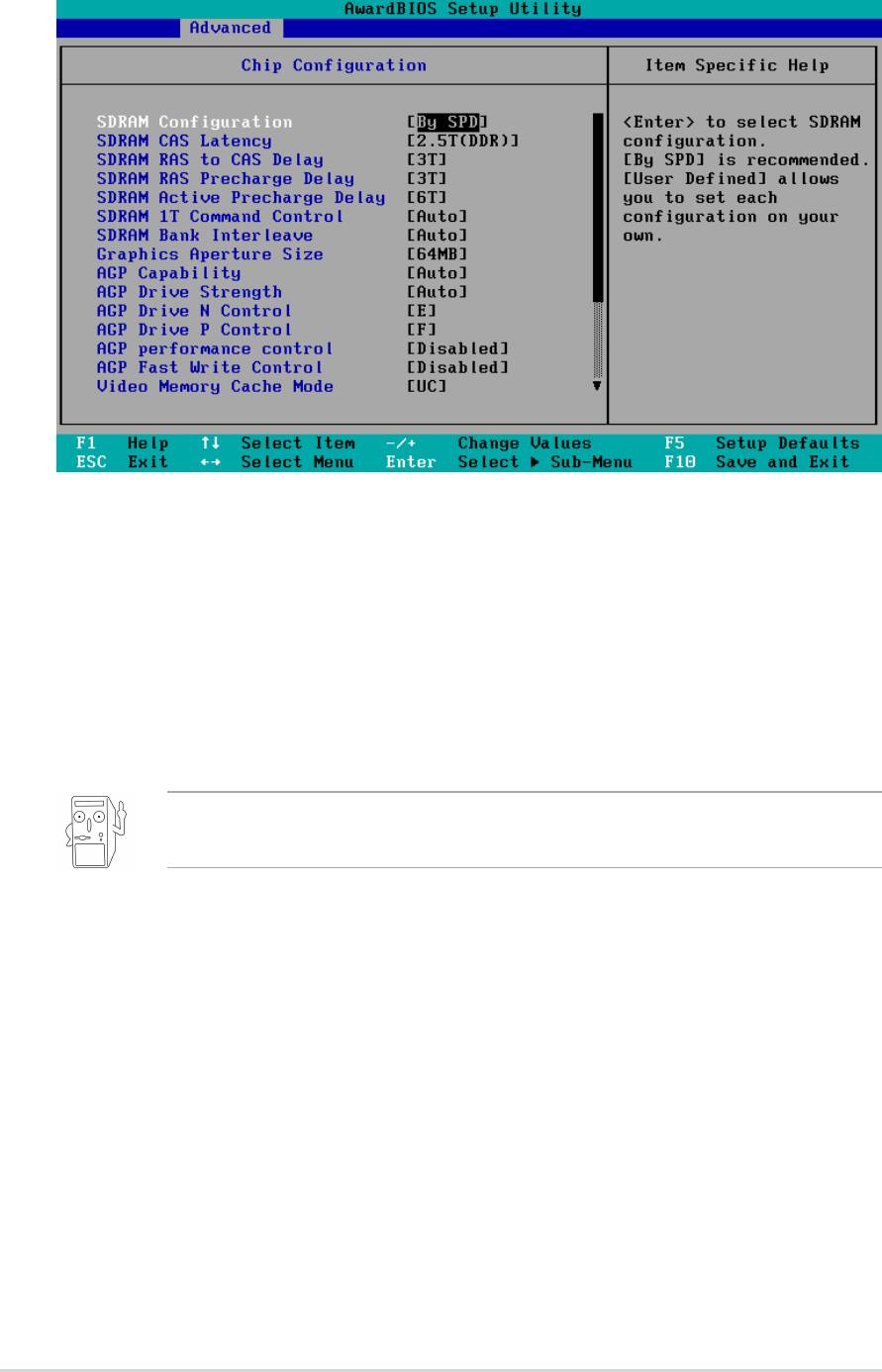
4.4.1 Chip Configuration
SDRAM Configuration [By SPD]
This parameter allows you to set the optimal timings for items 2–5,
depending on the memory modules that you are using. The default setting
is [By SPD], which configures items 2–5 by reading the contents in the
SPD (Serial Presence Detect) device. The EEPROM on the memory
module stores critical information about the module, such as memory type,
size, speed, voltage interface, and module banks.
Configuration options: [User Defined] [By SPD]
The SDRAM parameters (items 2~5) become configurable only when
you set the SDRAM Configuration to [User Defined].
SDRAM CAS Latency (value depends on SDRAM SPD)
This item controls the latency between the SDRAM read command and
the time the data actually becomes available. Configuration options: [1.5T]
[2T] [2.5T]
SDRAM RAS to CAS Delay (value depends on SDRAM SPD)
This item controls the latency between the DDR SDRAM active command
and the read/write command. Configuration options: [2T] [3T].
SDRAM RAS Precharge Delay (value depends on SDRAM SPD)
This item controls the idle clocks after issuing a precharge command to
the DDR SDRAM. Configuration options: [2T] [3T]
4-20
Chapter 4: BIOS Setup

SDRAM Active Precharge Delay (value depends on SDRAM SPD)
This item controls the number of DDR SDRAM clocks used for DDR
SDRAM parameters. Configuration options: [5T] [6T] [7T] [8T]
SDRAM 1T Command Control
Configuration options: [Disabled] [Enabled] [Auto]
SDRAM Bank Interleave
Configuration options: [Disabled] [2 Bank] [4 Bank] [Auto]
Graphics Aperture Size [64MB]
This feature allows you to select the size of mapped memory for AGP
graphic data. Configuration options: [4MB] [8MB] [16MB] [32MB] [64MB]
[128MB] [256MB] [512MB] [1024MB]
The [1024MB] and [512MB] configuration options are available only
when you use AGP 8X graphics card.
AGP Capability [8X Mode]
This motherboard supports the AGP 8X interface that enables enhanced
graphics performance with high bandwidth speeds up to 2.12GB/s.
AGP8X is backward-compatible. When set to [1X Mode], the AGP
interface only provides a peak data throughput of 266MB/s even if you are
using an AGP 8X card.
Configuration options: [Auto] [1X Mode] [2X Mode] [4X Mode] [8X Mode]
AGP Drive Strength [Auto]
Configuration options: [Auto] [Manual]
AGP Drive N Control [E]
Configuration options: [0][1][2][3][4][5][6][7][8][9][A][B][C][D][E][F]
AGP Drive P Control [F]
Configuration options: [0][1][2][3][4][5][6][7][8][9][A][B][C][D][E][F]
AGP performance control [Disabled]
Configuration options: [Disabled] [Enabled]
AGP Fast Write control [Disabled]
Configuration options: [Disabled] [Enabled]
ASUS A7V8X motherboard user guide
4-21

Video Memory Cache Mode [UC]
USWC (uncacheable, speculative write combining) is a new cache
technology for the video memory of the processor. It can greatly improve
the display speed by caching the display data. You must set this to UC
(uncacheable) if your display card does not support this feature, otherwise
the system may not boot. Configuration options: [UC] [USWC]
Memory Hole At 15M-16M [Disabled]
This field allows you to reserve an address space for ISA expansion cards.
Setting the address space to a particular setting makes that memory
space unavailable to other system components. Expansion cards can only
access memory up to 16MB. Configuration options: [Disabled] [Enabled]
Delayed Transaction [Disabled]
When set to [Enabled], this feature frees the PCI bus when the CPU is
accessing 8-bit ISA cards. This process normally consumes about 50-60
PCI clocks without PCI delayed transaction. Set this field to [Disabled]
when using ISA cards that are not PCI 2.1 compliant. Configuration
options: [Enabled] [Disabled]
Onboard PCI IDE [Both]
This field allows you to enable either the primary IDE channel or
secondary IDE channel, or both. You can also set both channels to
[Disabled]. Configuration options: [Both] [Primary] [Secondary] [Disabled]
DRAM Burst Length
Configuration options: [4] [Auto]
S2K Bus Driving Strength
Configuration options: [Auto] [Manual]
S2K Strobe P Control
Configuration options: [0][1][2][3][4][5][6][7][8][9][A][B][C][D][E][F]
S2K Strobe N Control
Configuration options: [0][1][2][3][4][5][6][7][8][9][A][B][C][D][E][F]
4-22
Chapter 4: BIOS Setup
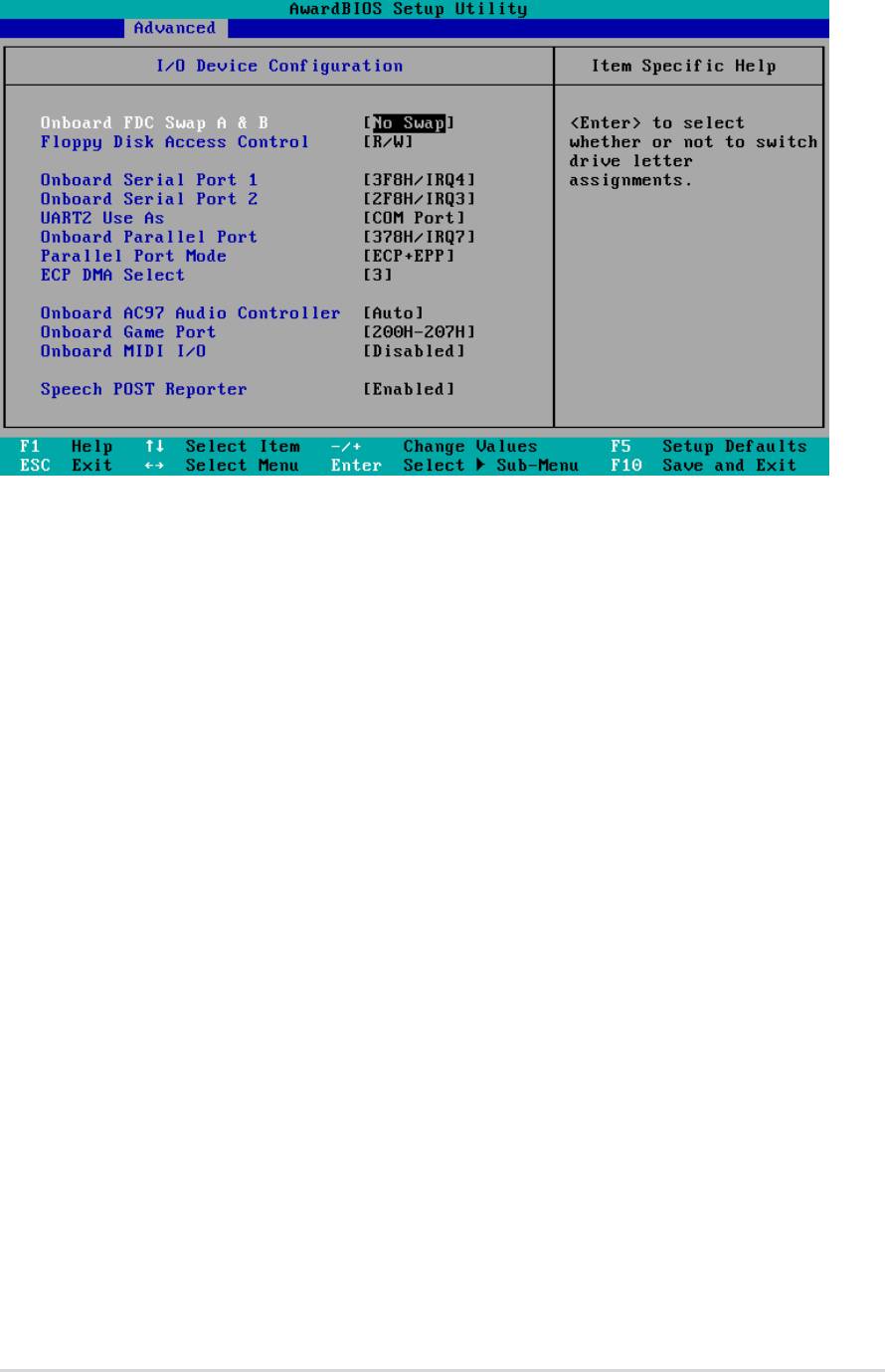
4.4.2 I/O Device Configuration
Onboard FDC Swap A & B
These fields set option to switch drive letter assignments. Configuration
Options: [No Swap] [Swap AB]
Floppy Disk Access Control [R/W]
When set to [Read Only], this parameter protects files from being copied to
floppy disks by allowing reads from, but not writes to, the floppy disk drive.
The default setting [R/W] allows both reads and writes. Configuration
options: [R/W] [Read Only]
Onboard Serial Port 1 [3F8H/IRQ4]
Onboard Serial Port 2 [2F8H/IRQ3]
These fields allow you to set the addresses for the onboard serial
connectors. Serial Port 1 and Serial Port 2 must have different addresses.
Configuration options: [3F8H/IRQ4] [2F8H/IRQ3] [3E8H/IRQ4] [2E8H/
IRQ10] [Disabled]
UART2 Use As [COM Port]
This field allows you to select the device on which to assign UART2.
Configuration options: [COM Port] [IR] [Smart Card Reader]
ASUS A7V8X motherboard user guide
4-23

Onboard Parallel Port [378H/IRQ7]
This field allows you to set the address of the onboard parallel port
connector. If you disable this field, the Parallel Port Mode and ECP DMA
Select configurations are not available. Configuration options: [Disabled]
[378H/IRQ7] [278H/IRQ5]
Parallel Port Mode [ECP+EPP]
This field allows you to set the operation mode of the parallel port.
[Normal] allows normal-speed operation but in one direction only; [EPP]
allows bidirectional parallel port operation; [ECP] allows the parallel port to
operate in bidirectional DMA mode; [ECP+EPP] allows normal speed
operation in a two-way mode. Configuration options: [Normal] [EPP] [ECP]
[ECP+EPP]
ECP DMA Select [3]
This field allows you to configure the parallel port DMA channel for the
selected ECP mode. This selection is available only if you select [ECP] or
[ECP+EPP] in Parallel Port Mode above. Configuration options: [1] [3]
Onboard AC97 Audio Controller [Auto]
These fields allow you to enable or disable the onboard AC97 audio
controller.Configuration options: [Auto] [Disabled]
Onboard Game Port [200H-207H]
These fields allow you to set the addresses for the onboard game
connectors. Game ports must have different addresses.
Configuration options: [200H/207H] [208H-20FH] [Disabled]
Onboard MIDI I/O [Disabled]
These fields allow you to set the addresses for the onboard MIDI
connectors. MIDI ports must have different addresses.
Configuration options: [330H-331H] [300H-301H] [Disabled]
Speech POST Reporter [Enabled]
This field enables or disables the ASUS POST Reporter™ feature. See
section “1.3 Special Features” and “3.2 Vocal POST messages” for more
information. Configuration options: [Disabled] [Enabled]
The buzzer warning sound is disabled if you enable the POST reporter.
4-24
Chapter 4: BIOS Setup
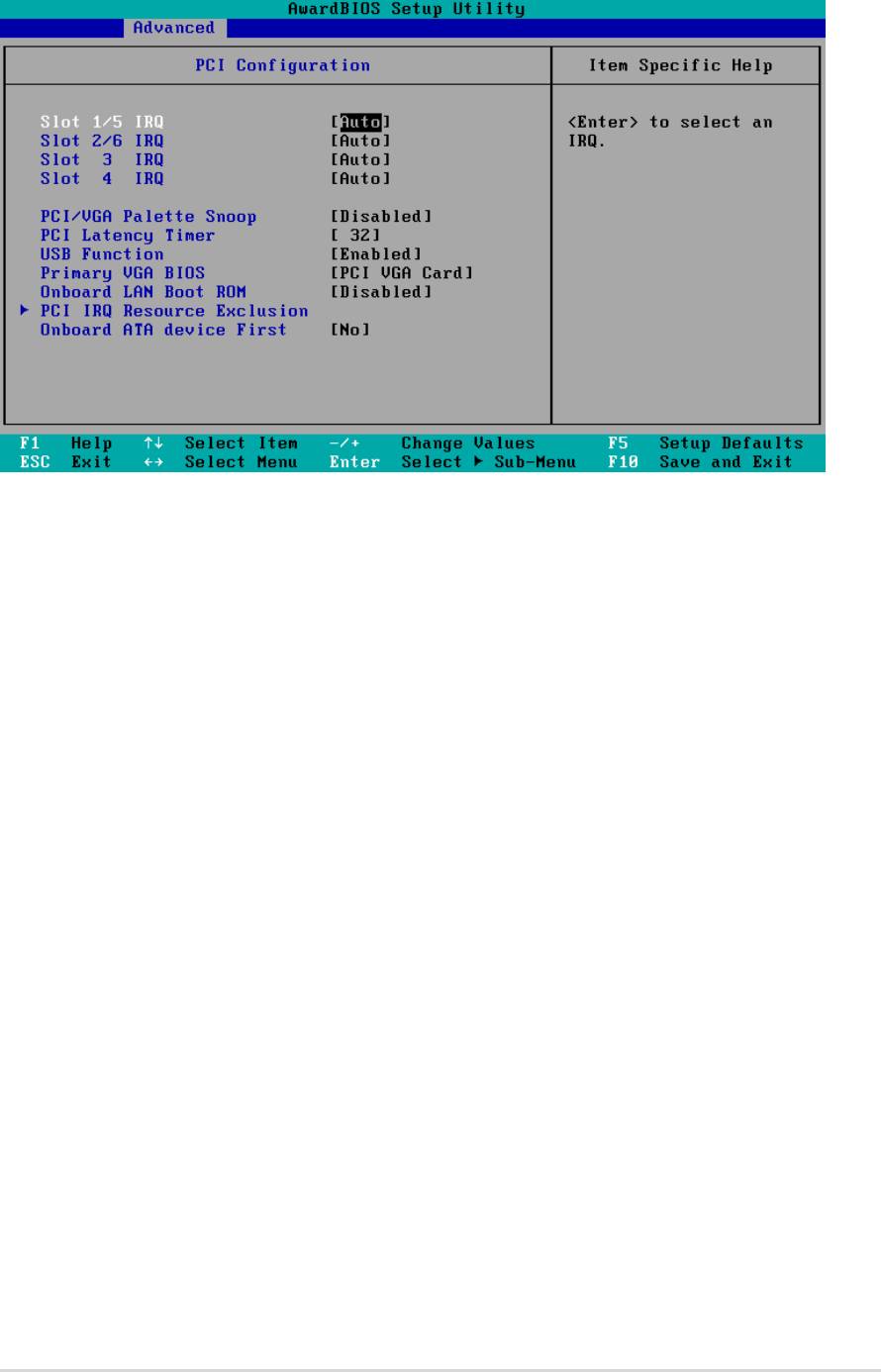
4.4.3 PCI Configuration
Slot 1/5, Slot 2, Slot 3, Slot 4, Slot 6 IRQ [Auto]
These fields automatically assign the IRQ for each PCI slot. The default
setting for each field is [Auto], which utilizes auto-routing to determine IRQ
assignments. Configuration options: [Auto] [NA] [3] [4] [5] [7] [9] [10] [11]
[12] [14] [15]
PCI/VGA Palette Snoop [Disabled]
Some non-standard VGA cards, like graphics accelerators or MPEG video
cards, may not show colors properly. Setting this field to [Enabled] corrects
this problem. If you are using standard VGA cards, leave this field to the
default setting [Disabled]. Configuration options: [Disabled] [Enabled]
PCI Latency Timer [32]
Leave this field to the default setting [32] for best performance and
stability.
USB Function [Enabled]
This field allows you to select the USB port that you wish to activate.
Configuration options: [Disabled] [Enabled]
Primary VGA BIOS [PCI VGA Card]
This field allows you to select the primary graphics card. Configuration
options: [PCI VGA Card] [AGP VGA Card]
ASUS A7V8X motherboard user guide
4-25
Onboard LAN Boot ROM
This field allows you to enable or disable the onboard LAN Boot ROM.
Configuration options: [Disabled] [Enabled]
Onboard ATA device First [No]
This field allows you to select the onboard ATA first.
Configuration options: [No] [Yes]
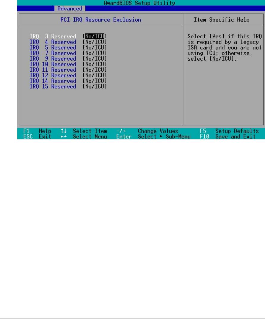
4.4.3.1 PCI IRQ Resource Exclusion
IRQ XX Reserved [No/ICU]
These fields indicate whether or not the displayed IRQ for each field is
being used by a legacy (non-PnP) ISA card. The setting [No/ICU] for an
IRQ field indicates that you are using the ISA Configuration Utility (ICU),
and that this particular IRQ is NOT required by a legacy ISA card. Set the
IRQ field to [Yes] if you install a legacy ISA card that requires a unique IRQ
and you are NOT using ICU. Configuration options: [No/ICU] [Yes]
4-26
Chapter 4: BIOS Setup
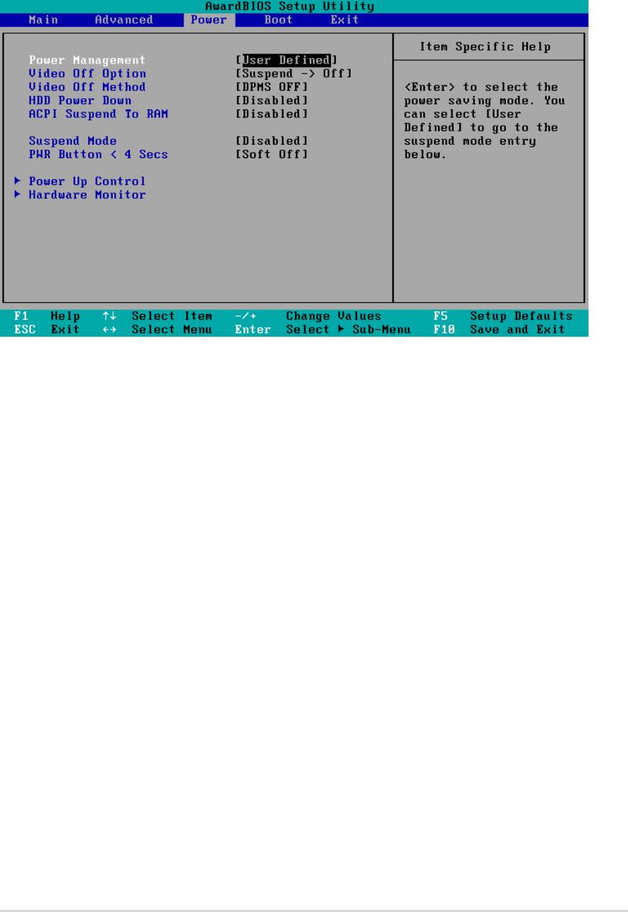
4.5 Power Menu
The Power menu allows you to reduce power consumption. This feature
turns off the video display and shuts down the hard disk after a period of
inactivity.
Power Management [User Defined]
This field allows you to activate or deactivate the automatic power saving
features. When set to [Disabled], the power management features do not
function regardless of the other settings on this menu. The [User Defined]
option allows you to set the period of inactivity before the system enters
suspend mode. Refer to “Suspend Mode” item.
When set to [Max Saving], system power is conserved to its greatest
amount. This setting automatically puts the system into suspend mode
after a brief period of system inactivity. [Min Saving] allows the least power
saving as the system enters suspend mode only after a long period of
inactivity. Configuration options: [User Defined] [Disabled] [Min Saving]
[Max Saving]
Video Off Option [Suspend -> Off ]
This field determines when to activate the video off feature for monitor
power management. Configuration options: [Always On] [Suspend -> Off]
ASUS A7V8X motherboard user guide
4-27

Video Off Method [DPMS OFF]
This field defines the video off features. The Display Power Management
System (DPMS) feature allows the BIOS to control the video display card if
it supports the DPMS feature. [Blank Screen] only blanks the screen. Use
this for monitors without power management or “green” features.
Even if installed, your screen saver does not display when you select
[Blank Screen] for the above field.
[V/H SYNC+Blank] blanks the screen and turns off vertical and horizontal
scanning. Configuration options: [Blank Screen] [V/H SYNC+Blank]
[DPMS Standby] [DPMS Suspend] [DPMS OFF] [DPMS Reduce ON]
HDD Power Down [Disabled]
Shuts down any IDE hard disk drives in the system after a period of
inactivity as set in this user-configurable field. This feature does not affect
SCSI hard drives. Configuration options: [Disabled] [1 Min] [2 Min] [3
Min]...[15 Min]
ACPI Suspend To RAM [Disabled]
This field allows you to enable or disable the ACPI Suspend-to-RAM
feature. To support this feature, the +5VSB of the power supply should
have the capacity to provide more than 720mA current. Configuration
options: [Disabled] [Enabled]
Suspend Mode [Disabled]
Sets the time period before the system goes into suspend mode.
Configuration options: [Disabled] [1~2 Min] [2~3 Min] [4~5 min] [8~9 Min]
[20 Min] [30 Min]
PWR Button < 4 Secs [Soft Off]
When set to [Soft off], the ATX switch can be used as a normal system
power-off button when pressed for less than 4 seconds. [Suspend] allows
the button to have a dual function where pressing less than 4 seconds
puts the system in sleep mode. Regardless of the setting, holding the ATX
switch for more than 4 seconds powers off the system. Configuration
options: [Soft off] [Suspend]
4-28
Chapter 4: BIOS Setup
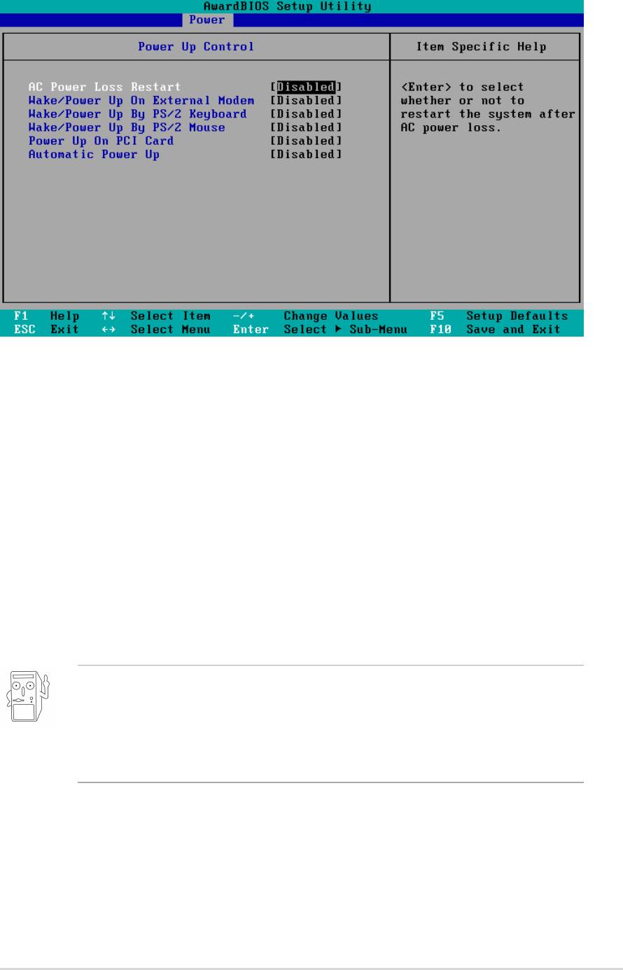
4.5.1 Power Up Control
AC PWR Loss Restart [Disabled]
This allows you to set whether or not to reboot the system after power
interruptions. [Disabled] leaves your system off while [Enabled] reboots the
system. [Previous State] sets the system back to the state it was before
the power interruption. Configuration options: [Disabled] [Enabled]
[Previous State]
Wake/Power Up On Ext. Modem [Disabled]
This allows either settings of [Enabled] or [Disabled] for powering up the
computer when the external modem receives a call while the computer is
in Soft-off mode. Configuration options: [Disabled] [Enabled]
The computer cannot receive or transmit data until the computer and
applications are fully running. Thus, connection cannot be made on the
first try. Turning an external modem off and then back on while the
computer is off causes an initialization string that turns the system
power on.
ASUS A7V8X motherboard user guide
4-29

Wake/Power Up By PS/2 Keyboard [Space Bar]
This parameter allows you to use specific keys on the keyboard to turn on
the system. This feature requires an ATX power supply that provides at
least 1A on the +5VSB lead. Configuration options: [Disabled] [Space Bar]
[Ctrl-Esc] [Power Key]
Wake/Power Up By PS/2 Mouse [Disabled]
When set to [Enabled], this parameter allows you to use the PS/2 mouse
to turn on the system. This feature requires an ATX power supply that
provides at least 1A on the +5VSB lead. Configuration options: [Disabled]
[Enabled]
Power Up On PCI Card [Disabled]
When set to [Enabled], this parameter allows you to turn on the system
through a PCI LAN or modem card. This feature requires an ATX power
supply that provides at least 1A on the +5VSB lead.
Configuration options: [Disabled] [Enabled]
Automatic Power Up [Disabled]
This allows an unattended or automatic system power up. You may
configure your system to power up at a certain time of the day by selecting
[Everyday] or at a certain time and day by selecting [By Date].
Configuration options: [Disabled] [Everyday] [By Date]
4-30
Chapter 4: BIOS Setup
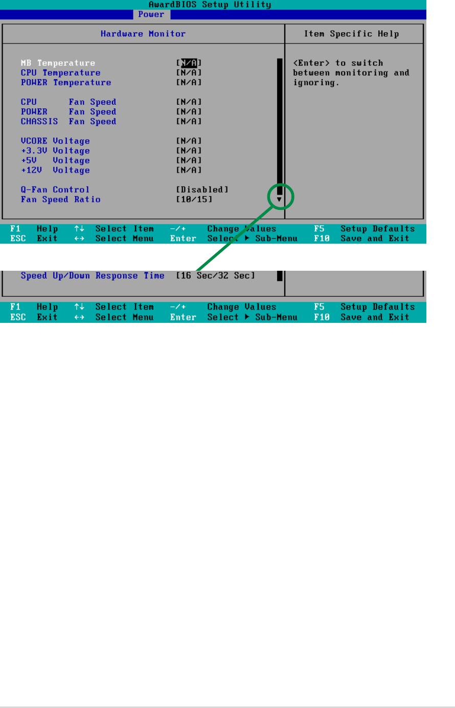
4.5.2 Hardware Monitor
MB Temperature [xxxC/xxxF]
CPU Temperature [xxxC/xxxF]
POWER Temperature [N/A]
The onboard hardware monitor automatically detects and displays the
motherboard and CPU temperatures.
If your power supply comes with a two-pin thermal sensor cable, connect
this cable to the TRPWR connector on the motherboard to allow BIOS to
auto-detect the power supply temperature (see page 2-29 for the location
of the TRPWR connector). The POWER temperature item shows N/A if
you do not have the appropriate power supply. Select [Ignore] to disable
the power temperature auto-detect function.
CPU Fan Speed [xxxxRPM] or [N/A]
Chassis Fan Speed [xxxxRPM] or [N/A]
Power Fan Speed [xxxxRPM] or [N/A]
The onboard hardware monitor automatically detects and displays the
CPU, chassis, and power fan speeds in rotations per minute (RPM). If any
of the fans is not connected to the motherboard, the specific field shows
N/A.
ASUS A7V8X motherboard user guide
4-31

VCORE Voltage, +3.3V Voltage, +5V Voltage, +12V Voltage
The onboard hardware monitor automatically detects the voltage output
through the onboard voltage regulators.
Q-Fan Control [Disabled]
This item allows you to enable or disable the ASUS Q-Fan feature that
smartly adjusts the fan speeds for more efficient system operation. When
this field is set to [Enabled], the Fan Speed Ratio and Speed Up/Down
Response Time
items appear to allow selection of the appropriate fan
speeds and the corresponding response time. Configuration options:
[Disabled] [Enabled]
Fan Speed Ratio [10/15]
This item allows you to select the appropriate fan speed ratio for the
system. The default [10/15] is the minimum fan speed ratio. Select a
higher ratio if you installed additional devices and the system requires
more ventilation. This item appears only when the Q-Fan Control item is
set to [Enabled]. Configuration options: [10/15] [11/15] [12/15] [13/15]
[14/15] [Full Speed]
Speed Up/Down Response Time [16 Sec/32Sec]
This item indicates the time period before the fan speeds adjust to the
value set in the Fan Speed Ratio field. This item appears only when the
Q-Fan Control item is set to [Enabled]. Configuration options:
[16 Sec/32 Sec] [32 Sec/64 Sec] [48 Sec/96 Sec] [64 Sec/128 Sec]
If any of the monitored items is out of range, the following error
message appears: “Hardware Monitor found an error. Enter Power
setup menu for details”. You will then be prompted to “Press F1 to
continue or DEL to enter SETUP”.
4-32
Chapter 4: BIOS Setup
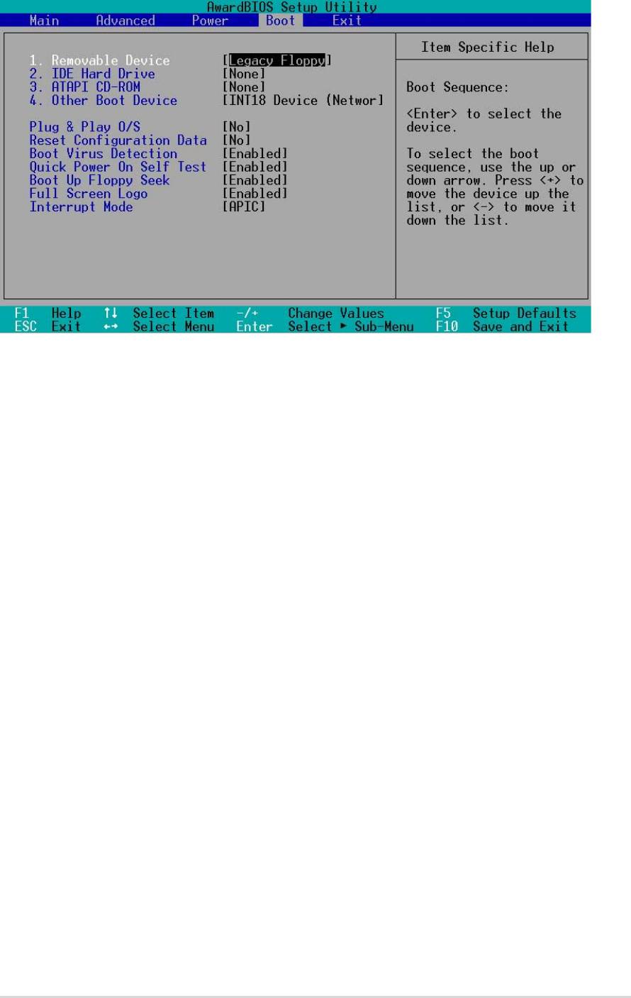
4.6 Boot Menu
Boot Sequence
The Boot menu allows you to select among the four possible types of boot
devices listed using the up and down arrow keys. By using the <+> or
<Space> key, you can promote devices and by using the <-> key, you can
demote devices. Promotion or demotion of devices alters the priority which
the system uses to search for a boot device on system power up.
Configuration fields include Removable Devices, IDE Hard Drive, ATAPI
CD-ROM, and Other Boot Device.
Removable Device [Legacy Floppy]
Configuration options: [Disabled] [Legacy Floppy] [LS-120] [ZIP]
[ATAPIMO]
IDE Hard Drive
This field allows you to select which IDE hard disk drive to use in the boot
sequence. Pressing [Enter] will show the product IDs of all connected IDE
hard disk drives.
ATAPI CD-ROM
This field allows you to select which ATAPI CD-ROM drive to use in the
boot sequence. Pressing [Enter] will show the product IDs of all your
connected ATAPI CD-ROM drives.
Other Boot Device Select [INT18 Device (Network)]
Configuration options: [Disabled] [SCSI Boot Device] [INT18 Device
(Network)]
ASUS A7V8X motherboard user guide
4-33

Plug & Play O/S [No]
This field allows you to use a Plug-and-Play (PnP) operating system to
configure the PCI bus slots instead of using the BIOS. When [Yes] is
selected, interrupts may be reassigned by the OS. If you installed a non-
PnP OS or if you want to prevent reassigning of interrupt settings, keep
the default setting [No]. Configuration options: [No] [Yes]
Reset Configuration Data [No]
The Extended System Configuration Data (ESCD) contain information
about non-PnP devices. It also holds the complete record of how the
system was configured the last time it was booted. Select [Yes] if you want
to clear these data during the Power-On-Self-Test (POST).
Configuration options: [No] [Yes]
Boot Virus Detection [Enabled]
This field allows you to set boot virus detection, ensuring a virus-free boot
sector. The system halts and displays a warning message when it detects
a virus. If this occurs, you can either allow the operation to continue or use
a virus-free bootable floppy disk to restart and investigate your system.
Configuration options: [Disabled] [Enabled]
Quick Power On Self Test [Enabled]
This field speeds up the Power-On-Self Test (POST) routine by skipping
retesting a second, third, and fourth time. Configuration options: [Disabled]
[Enabled]
Boot Up Floppy Seek [Enabled]
When enabled, the BIOS will seek the floppy disk drive to determine
whether the drive has 40 or 80 tracks. Configuration options: [Disabled]
[Enabled]
Full Screen Logo [Enabled]
This allows you to enable or disable the full screen logo display feature.
Configuration options: [Disabled] [Enabled]
Make sure that the above item is set to [Enabled] if you wish to use the
ASUS MyLogo2™ feature.
Interrupt Mode [APIC]
The Advanced Programmable Interrupt Controller (APIC) setting allows
you to distribute interrupt routings other than the 16 IRQs. The
Programmable Interrupt Controller (PIC) setting allows you to use the 16
IRQs only. Configuration options: [PIC] [APIC]
4-34
Chapter 4: BIOS Setup
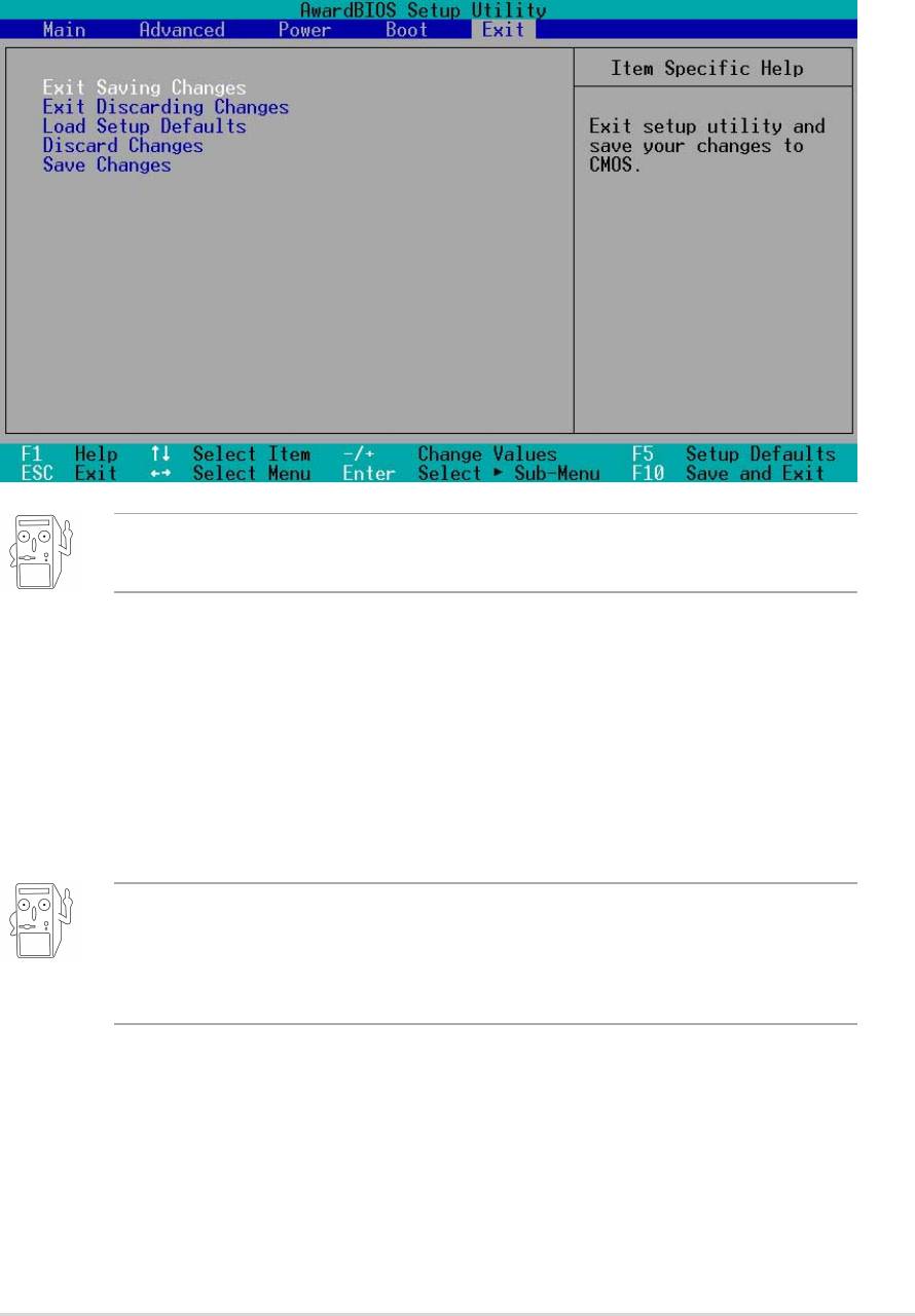
4.7 Exit Menu
When you have made all of your selections from the various menus in the
Setup program, save your changes and exit Setup. Select Exit from the
menu bar to display the following menu.
Pressing <Esc> does not immediately exit this menu. Select one of the
options from this menu or <F10> from the legend bar to exit.
Exit Saving Changes
Once you are finished making your selections, choose this option from the
Exit menu to ensure the values you selected are saved to the CMOS RAM.
The CMOS RAM is sustained by an onboard backup battery and stays on
even when the PC is turned off. When you select this option, a
confirmation window appears. Select [Yes] to save changes and exit.
If you attempt to exit the Setup program without saving your changes,
the program prompts you with a message asking if you want to save
your changes before exiting. Pressing <Enter> saves the changes
while exiting.
Exit Discarding Changes
Select this option only if you do not want to save the changes that you
made to the Setup program. If you made changes to fields other than
system date, system time, and password, the BIOS asks for a confirmation
before exiting.
ASUS A7V8X motherboard user guide
4-35

Load Setup Defaults
This option allows you to load the default values for each of the
parameters on the Setup menus. When you select this option or if you
press <F5>, a confirmation window appears. Select [Yes] to load default
values. Select Exit Saving Changes or make other changes before saving
the values to the non-volatile RAM.
Discard Changes
This option allows you to discard the selections you made and restore the
previously saved values. After selecting this option, a confirmation
appears. Select [Yes] to discard any changes and load the previously
saved values.
Save Changes
This option saves your selections without exiting the Setup program. You
can then return to other menus and make further changes. After you select
this option, a confirmation window appears. Select [Yes] to save any
changes to the non-volatile RAM.
4-36
Chapter 4: BIOS Setup
