Asus P5W: 1.8 Front panel cables
1.8 Front panel cables: Asus P5W
Table of contents
- Chapter 1: Quick Start 1.1 Installing the CPU
- 1.1.2 AMD AM2 Socket
- 1.2 Installing the heatsink and fan
- For Intel-certied heatsink:
- For AMD-certied heatsink:
- 1.3 Installing a DIMM 1.4 Installing the motherboard
- Chapter1: QuickStart
- 1.5 Installing the power supply unit
- 1.6 Installing an expansion card
- 1.7 Installing disk drives
- 1.7.2 SATA optical disk drive
- 1.7.3 Floppy disk drive
- 1.7.4 PATA hard disk drive
- Notes for installing PATA hard disk drive
- 1.7.5 SATA hard disk drive
- 1.8 Front panel cables
- ASUS Q-Connector 1.9 Connecting the ATX power
- Power connectors
- 1.10 Peripheral devices and accessories
- 1.11 Startingupforthersttime Troubleshooting
- Chapter 2: Manage/update BIOS 2.1 AFUDOS utility
- ASUS Motherboard installation guide
- 2.2 Award BIOS Flash Utility
- ASUS Motherboard installation guide
- Saving the current BIOS le
- 2.3 ASUS Update utility Installing ASUS Update
- Updating the BIOS through the Internet
- Updating the BIOS through a BIOS le
- Chapter 3: Troubleshooting 3.1 Troubleshooting for Motherboard DIY 3.1.1 Basic troubleshooting
- B. CPU overheated
- 3.2 Other common troubles
- 3.2.1 No power
- 3.2.2 Failure to boot-up; No screen display 3.2.3 Failure to enter the operating system
- 3.2.4 FAQs
- Chapter 4: Computer care tips
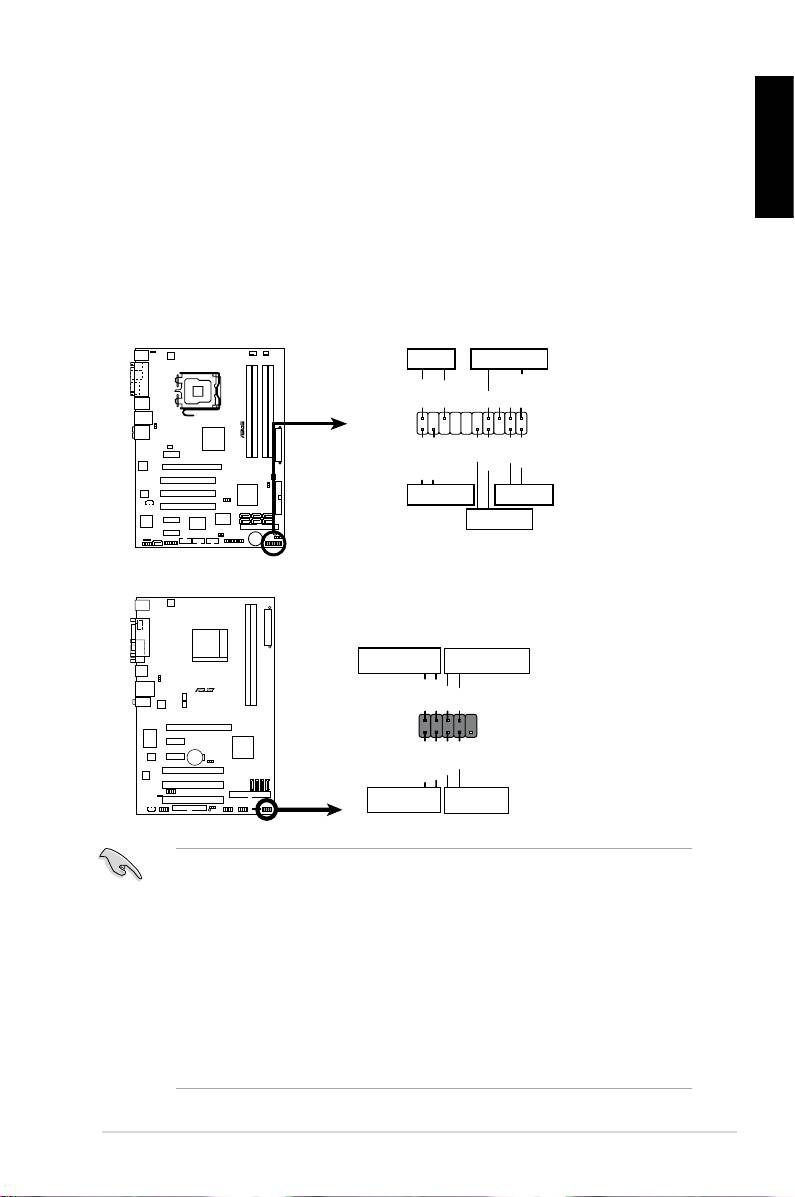
1.8 Front panel cables
Toconnectthefrontpanelcables:
• RESET (Reset Switch)
English
• PLED(PowerLED)
• PWRSW(PowerSwitch)
• IDE_LED(IDEHardDiskActiveLED)
• SPEAKER (Speaker Connector)
ASUS Motherboard installation guide
19
PWRLED PWRBTN
M2N-X
PLED+
PLED-
PWR
GNDReset
F_PANEL
Ground
IDELED+
IDELED-
HD LED RESET
PLED SPEAKER
P5B-E
PLED+
PLED-
+5V
Ground
Ground
Speaker
®
PANEL
PWR
Reset
Ground
Ground
IDE_LED+
IDE_LED-
IDE_LED
RESET
PWRSW
*
Requires an ATX power supply.
20-8 pin front panel connector
PIN1
PIN1
10-1 pin front panel connector
• Thefrontpanelcablesofyourchassismaydifferwithmodelsordesigns.
Connect these connectors to the motherboard according to the label.
• IftheLEDsdonotlightupandthepinloctioniscorrect,youmightmisplace
thegroundpinswiththesignalpins.Usuallythewhitewirestandsforthe
ground pins and the color‑coded wire for the signal pins.
• TheSPEAKER,RESETandPWRSWfrontpanelcableshavenospecic
orientation,whileIDE_LEDandPLEDcablesdo.Connectthethecable
PIN1 to the connector PIN1 on the motherboard.
• Thefrontpanelconnectorvarieswithyourmotherboardmodel,refertothe
user guide for more information.
