Kenwood MG470: System connection
System connection: Kenwood MG470
System connection
Unpacking
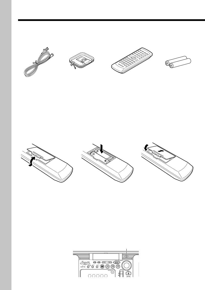
Unpack the unit carefully and make sure that all the accessories are present.
POWER cord (1) Remote control unit (1) Batteries(R6/AA)
AM loop antenna (1)
for remote (2)
If any accessories are missing, or if the unit is damaged or fails to operate, notify your dealer
immediately. If the unit was shipped to you directly, notify your shipper immediately. Kenwood
recommends that you retain the original carton and packing materials in case you need to
move or ship the unit in the future.
Keep this manual handy for future reference.
Loading batteries in the remote control unit
(1) Remove the battery com-
(2) Insert two R6("AA"-size) batter-
(3) Attach the battery com-
partment cover of the re-
ies following the polarity indi-
partment cover.
mote.
cations.
÷ The provided batteries are intended for use in operation checking, and their service life may be
short.
÷ When the remote-controllable distance becomes short, replace both of the batteries with new
ones.
÷ If direct sunlight or the light of a high-frequency fluorescent lamp (inverter type, etc.) is incident to
the remote sensor on the main unit front panel, malfunction may occur. In such a case, change the
installation position to avoid malfunction.
÷ When pressing more than one remote control keys successively, press each key securely by
leaving an interval of 1 second or more between keys.
÷ The standard remote-control range is within about 6 meters from the main unit front panel. Be
sure to point the remote to remote sensor on the front panel.
remote sensor
EN
4
Connecting the accessories
Preparation
section
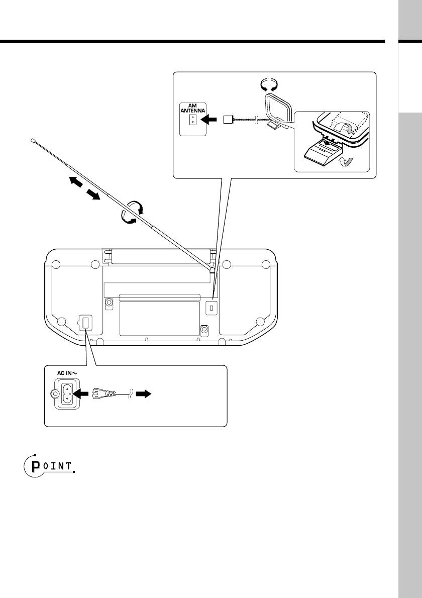
Antenna assembly
FM rod antenna
method
Extend the FM antenna and ori-
ent it to obtain the best receiv-
ing condition possible.
AM loop antenna
The provided antenna has been designed
for indoor use. Place it in a position as
apart as possible from a TV and power
cords and orient it to obtain the best re-
ceiving condition.
÷ When removing the power cord con-
To wall AC outlet
nection, unplug the power plug of the
wall outlet first.
POWER cord
÷ Be sure to insert each connection cord securely. If a cord is plugged in incompletely, audio may not
be output or noise may be generated.
÷ Before connecting or disconnecting any connection cord, be sure to first unplug the power cord
from the wall power outlet.
÷ Do not install the speakers near a TV set. Otherwise, color irregularities due to magnetism may be
observed on the TV screen.
÷ Be sure to put the unit to the STANDBY mode (page 71) before plugging or unplugging the power cord.
Continued on next page
\
EN
5
System connection (continued)
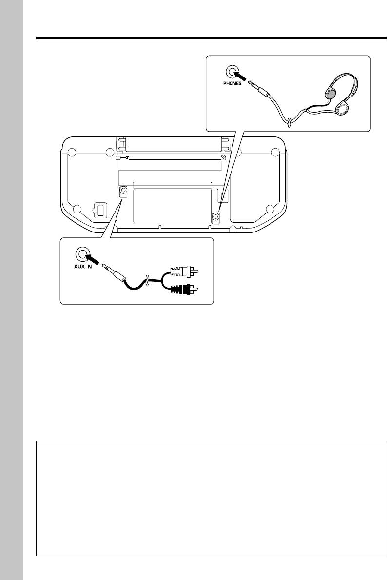
Connecting other components
headphones
Plug the optional headphones equipped
with stereo mini-plugs.
÷ When listening audio through
speakers, unplug the headphones
from the PHONES jack.
AUX (auxiliary) component
An additional MD player, cassette tape or analog turntable with built-in equalizer (such as the
P-110) which are available separately can optionally be connected to the system using an
audio cable with stereo mini-plugs (option).
÷ The AUX IN terminals are input jacks. An AUX component for use in recording cannot be con-
nected to the system.
÷ When recording an AUX component, also read the instruction manual of the component.
÷ When an analog turntable is connected and located in proximity of the system, howling noise may
interfere with the system when the listening volume is increased. In this case, install the analog
turntable farther apart from the system.
÷ The input level from the AUX component can be adjusted on this system. (page 29)
In regard to demonstration
This unit incorporates a demonstration mode (display only). The demonstration shows the
display conditions of various operation modes by switching them sequentially, but the
audio does not vary during it.
When the power supply fails and restores or the power cord is unplugged and plugged
during operation, the unit automatically enters the demonstration mode ("DEMO ON").
To cancel demonstration mode : Press the SET/(DEMO) key while "DEMO ON" is displayed.
To enter demonstration mode : Keep on pressing the SET/(DEMO) key for more than 2 sec-
onds while the unit is ON.
EN
6
Оглавление
- Before applying power
- Contents
- System connection
- Adjusting the present time
- Presetting radio stations
- Playback of CD
- Playback of MD
- Playback of TAPE
- Receiving broadcast stations
- Playing audio input from AUX component
- Recording CD onto MD (MD O.T.E.)
- Recording CD onto TAPE (TAPE O.T.E.)
- Displayed information
- Adjusting the tone
- Adjusting the AUX input Muting the audio tempo- level rarily (MUTE)
- Playing CD or MD tracks
- Repeating a CD or MD Playing a CD or MD in a (REPEAT) random (RANDOM)
- Stereo LP modes
- Setting the recording mode
- High-speed recording of
- Recording onto MD
- Recording onto TAPE
- Recording CD tracks onto
- Recording MD tracks onto
- Recording only the first
- Editing the MD titles
- Moving one track
- Moving several tracks at a time
- Combining tracks
- Dividing a track
- Erasing a track
- Erasing several tracks at
- Canceling editing
- Waking up to the timer
- Program timer
- Sleep timer (SLEEP) Auto power save (A.P.S.)
- Important items
- In case of difficulty
- Display message list
- Specifications
- Controls and indicators
