Kenwood KDV-5241UY: инструкция
Раздел: Автомобильная техника
Тип: Мультимедиа
Инструкция к Мультимедиа Kenwood KDV-5241UY
1
DEUTSCH
WARNUNG
• Wenn Sie ein Zündungskabel (rot) und ein Batteriekabel
(gelb) an das Chassis des Fahrzeugs (Erde) anschließen,
könnten Sie einen Kurzschluss verursachen, der zu einem
Brand führt. Schließen Sie diese Kabel immer an eine
Stromquelle an, die durch den Sicherungskasten führt.
ACHTUNG
•
Einbau und Verkabelung dieses Produkts erfordern
Fachwissen und Erfahrung. Aus Sicherheitsgründen
sollten Einbau und Verkabelung von Fachpersonal
durchgeführt werden.
•
Betreiben Sie das Gerät ausschließlich mit 12-Volt-
Gleichstrom und negativer Masseverbindung.
•
Schützen Sie das Gerät vor direkter Sonneneinstrahlung,
zu hohen Temperaturen, Feuchtigkeit, Spritzwasser und
Staub. Vermeiden Sie bei der Installation zudem Orte
mit zu viel Staub oder Spritzwasser.
•
Verwenden Sie auf keinen Fall Ihre eigenen Schrauben.
Verwenden Sie ausschließlich die im Lieferumfang
enthaltenen Schrauben. Zu lange oder zu dicke
Schrauben könnten das Gerät beschädigen.
•
Falls das Zündschloss Ihres Fahrzeugs über keine
ACC-Stellung verfügt, oder falls das Zündkabel an eine
Stromquelle mit Konstantspannung wie beispielsweise ein
Batteriekabel angeschlossen ist, wird die Stromversorgung
des Geräts nicht mit der Zündung verbunden (d. h. das
Gerät wird nicht zusammen mit der Zündung ein- und
ausgeschaltet). Wenn Sie die Stromversorgung des
Geräts mit der Zündung verbinden wollen, schließen
Sie das Zündkabel an eine Stromquelle an, die mit dem
Zündschlüssel ein- und ausgeschaltet werden kann.
•
Wenn die Konsole über eine Klappe verfügt, stellen Sie
bitte sicher, dass Sie das Gerät so installieren, dass das
Bedienfeld beim Schließen und Öffnen nicht an die
Klappe stößt.
•
Wenn die Sicherung durchbrennt, stellen Sie bitte zuerst
sicher, dass sich die Kabel nicht berühren, damit es zu
keinem Kurzschluss kommt; tauschen Sie anschließend
die alte Sicherung durch eine neu mit den selben
Nennwerten aus.
•
Isolieren Sie nicht angeschlossene Kabel mit Vinylband
oder ähnlichem Material. Um einen Kurzschluss zu
vermeiden, entfernen Sie bitte auf keinen Fall die Kappen
an den Enden der nicht angeschlossenen Kabel oder
Anschlüsse.
•
Prüfen Sie nach dem Einbau, ob Bremslichter, Blinker
und Scheibenwischer einwandfrei funktionieren.
•
Der Fahrer darf während der Fahrt auf keinen Fall auf
den Monitor sehen.
Wenn die Feststellbremse nicht verriegelt ist, erscheint
„FAHRER DARF MONITOR NICHT BEIM FAHREN
BETRACHTEN.“ auf dem Monitor und es wird kein
Wiedergabebild angezeigt.
– Diese Warnung erscheint nur dann, wenn der Draht
der Feststellbremse mit dem Feststellbremssystem des
Fahrzeugs verbunden ist.
•
Das Abstrahlblech wird nach dem Gebrauch sehr
heiß. Beim Ausbau des Geräts darauf achten, das
Abstrahlblech nicht zu berühren.
ITALIANO
AVVERTENZE
• Se si collega il cavo di accensione (rosso) e il cavo della
batteria (giallo) al telaio dell’automobile (terra), può
verificarsi un corto circuito, che a sua volta potrebbe
causare un incendio. Collegare sempre i cavi alla fonte
di alimentazione che attraversa la scatola dei fusibili.
ATTENZIONE
•
Il montaggio e il cablaggio del prodotto richiedono
abilità ed esperienza. Ai fini della sicurezza, far
eseguire i lavori di montaggio e cablaggio ad un
professionista.
•
Alimentare l’apparecchio esclusivamente con una
tensione nominale di 12 V CC, con polo negativo a
massa.
•
Non installare l’apparecchio in un luogo esposto alla
luce solare diretta, a calore o umidità eccessivi. Evitare
anche luoghi molto polverosi o soggetti a schizzi
d’acqua.
•
Non utilizzare viti non appropriate. Utilizzare solo le
viti in dotazione. Se si utilizzano viti errate, è possibile
danneggiare l’unità.
•
Se l’interruttore dell’accensione del proprio
veicolo non è dotato di posizione ACC, o se il
cavo dell’accensione è collegato ad una fonte di
alimentazione con tensione costante come il cavo
della batteria, l’alimentazione dell’apparecchio non
sarà in connessione con l’interruttore dell’accensione
(cioè l’apparecchio non si accenderà e non si
spegnerà in sincronizzazione con l’accensione e lo
spegnimento del motore). Se desiderate mettere in
connessione l’alimentazione dell’apparecchio con
l’interruttore dell’accensione del veicolo, collegate il
cavo dell’accensione ad una fonte di alimentazione
che possa essere attivata e disattivata con la chiavetta
di accensione.
•
Se la consolle ha un coperchio, assicurarsi di installare
l’unità in modo che il frontalino non urti il coperchio
quando viene aperto e chiuso.
•
Se il fusibile si dovesse bruciare, assicurarsi
innanzitutto che i cavi non siano in contatto, in modo
da evitare un corto circuito, quindi sostituire il fusibile
usato con uno nuovo della stessa portata.
•
Isolare i cavi non collegati con del nastro in vinile o un
altro materiale simile. Per evitare corto circuiti, non
rimuovere i coperchi all’estremità dei cavi scollegati o
dei terminali.
•
Dopo avere installato l’unità, controllare che le
luci dei freni, gli indicatori, il tergicristallo e così via
dell’automobile funzionino correttamente.
•
Il conducente non deve guardare il monitor mentre è
alla guida.
Se il freno di stazionamento non è innestato,
sul monitor viene visualizzata l’indicazione “IL
CONDUCENTE NON DEVE GUARDARE IL MONITOR
MENTRE STA GUIDANDO.” e le immagini riprodotte
non vengono visualizzate.
– Questo messaggio di avvertimento viene
visualizzato solo se il cavo del freno di
stazionamento è collegato all’impianto
corrispondente integrato nell’auto.
•
Dopo l’uso, il dissipatore di calore si surriscalda.
Evitare di toccarlo quando si estrae l’apparecchio.
РУCCKИЙ
ПРЕДУПРЕЖДЕНИЕ
• Подсоединение провода зажигания (красный) и
провода батареи (желтый) к корпусу автомобиля
(заземление) может привести к короткому
замыканию, которое в свое очередь может вызвать
возгорание. Подсоединяйте эти провода только
к источнику питания, снабженному закрытым
плавким предохранителем.
ВHИMAHИE
•
Установка и подключение данного изделия требует
умений и опыта. Из соображений безопасности
предоставьте осуществление установки и
подключения профессионалам.
•
Cледует соединить заземление аппарата
с отрицательным полюсом источника
электропитания 12 B постоянного тока.
•
Не устанавливайте устройство в местах,
подвергающихся воздействию прямых солнечных
лучей, и в местах с повышенной температурой или
влажностью. Также избегайте сильно запыленных
мест и мест, где на устройство могут попасть
брызги воды.
•
При установке не применяйте никаких винтов,
кроме винтов, поставленных вместе с устройством.
Применение других винтов может привести к
повреждению устройства.
•
Eсли зажигание вашего автомобиля не имеет
положения АCC, или если кабель зажигания
присоединен к источнику питания с постоянным
напряжением, как, например, батарейный кабель,
питание не будет соединено с зажиганием (то есть
не будет включаться и выключаться одновременно
с зажиганием). Eсли Вы хотите соединить питание
устройства с зажиганием, следует присоединить
кабель зажигания к источнику питания, который
можно включать и выключать с помощью ключа
зажигания.
•
Если консоль снабжена крышкой, устанавливайте
устройство таким образом, чтобы передняя
панель не задевала крышку при ее открывании и
закрывании.
•
Если сгорел предохранитель, прежде всего
убедитесь в отсутствии короткого замыкания
проводов, а затем установите новый
предохранитель с такими же характеристиками.
•
Изолируйте отсоединенные провода виниловой
лентой или подобным материалом. Во избежание
короткого замыкания не снимайте колпачки с
концов отсоединенных проводов или контактов.
•
После того, как устройство установлено, проверьте
правильность работы ламп тормозов, указателей
поворота, дворников и т.д.
•
Водителю не следует смотреть на монитор во
время вождения.
Если стояночный тормоз не включен, на мониторе
появляется сообщение “BОДИТЕЛЬ НЕ ДОЛЖЕН
СМОТРЕТЬ НА МОНИТОР ВО ВРЕМЯ ВОЖДЕНИЯ.” и
изображение воспроизведения отображаться не
будет.
– Это предупреждение появляется только в том
случае, если провод стояночного тормоза
подключен к стояночной тормозной системе
автомобиля.
•
Радиатор во время использования сильно
нагревается. Старайтесь его не трогать во время
удаления устройства.
Heat sink
Abstrahlblech
Dissipatore di calore
Радиатор
J
Rubber cushion
Gummipuffer
Gommino
Резиновый чехол
F
Crimp connector
Quetschanschluß
Cosse à sertir
Обжимной соединитель
G
Washer (ø5)
Unterlegscheibe (ø5)
Rondelle (ø5)
Шайба (њ5)
H
Lock nut (M5)
Sicherungsmutter (M5)
Ecrou d’arrêt (M5)
Фиксирующая гайка (M5)
I
Mounting bolt (M5
×
20 mm)
Befestigungsschraube (M5 × 20 mm)
Bullone di montaggi (M5 × 20 mm)
Крепежный болт (M5 × 20 мм)
C
Sleeve
Halterung
Protezione
Муфта
E
Power cord
Stromkable
Cavo di alimentazione
Кабель питания
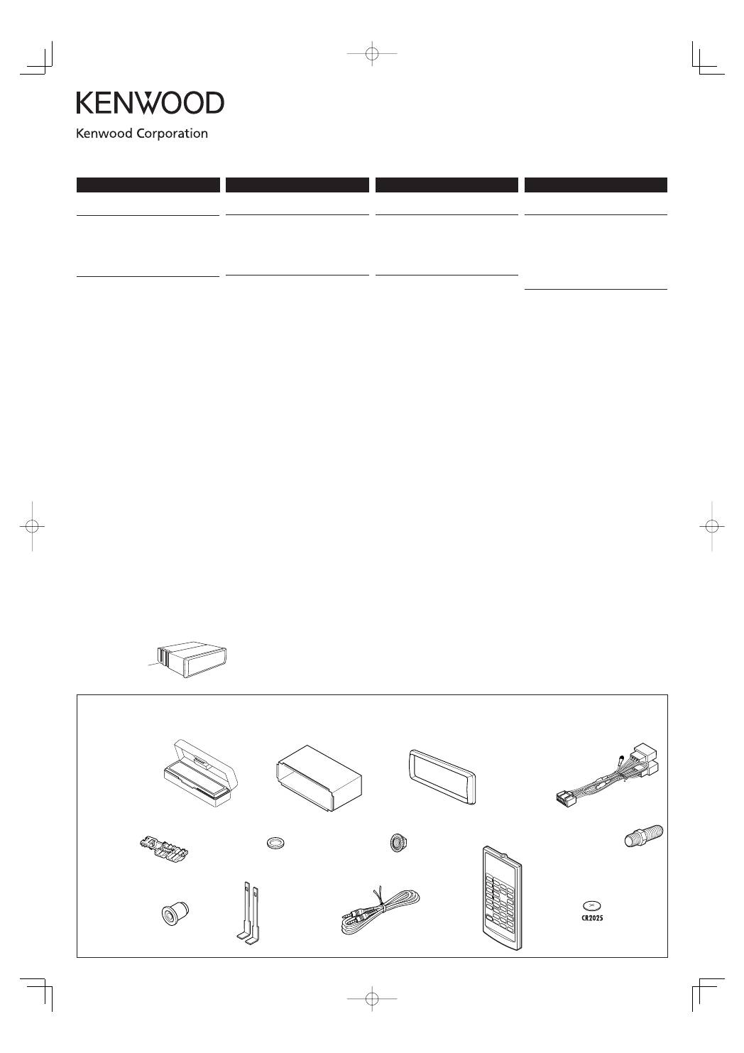
Parts list for installation and
connection
If any item is missing, consult your Kenwood Car
Audio dealer immediately.
K
Handles
Griffe
Maniglie
Рычаги
Componenti da usare per
l’installazione ed il collegamento
Se uno degli articoli manca, rivolgersi
immediatamente al proprio rivenditore di sistemi
audio per auto Kenwood.
D
Trim plate
Frontrahmen
Piastra di finitura
Декоративную панель
Список деталей для установки и
подключения
Если отсутствует какая-либо деталь, немедленно
обратитесь к дилеру систем автозвука Kenwood.
KDV-5241U
Installation/Connection Manual
Manual de instalación/conexión
Manuel d’installation/raccordement
Руководство по установке/подключению
©2008 B54-4681-08/00(E)
GET0559-002A
ENGLISH
WARNING
• If you connect the ignition wire (red) and the battery
wire (yellow) to the car chassis (ground), you may cause
a short circuit, that in turn may start a fire. Always
connect those wires to the power source running
through the fuse box.
CAUTION
•
Mounting and wiring this product requires skills and
experience. For safety’s sake, leave the mounting and
wiring work to professionals.
•
Make sure to ground the unit to a negative 12V DC
power supply.
•
Do not install the unit in a spot exposed to direct
sunlight or excessive heat or humidity. Also avoid places
with too much dust or the possibility of water splashing.
•
Do not use your own screws. Use only the screws
provided. If you use the wrong screws, you could
damage the unit.
•
If your vehicle’s ignition does not have an ACC
position, or if the ignition wire is connected to a power
source with constant voltage such as a battery wire, the
power will not be linked with the ignition (i.e., it will
not turn on and off along with the ignition). If you want
to link the unit’s power with the ignition, connect the
ignition wire to a power source that can be turned on
and off with the ignition key.
•
If the console has a lid, make sure to install the unit so
that the faceplate will not hit the lid when closing and
opening.
•
If the fuse blows, first make sure the wires aren’t
touching to cause a short circuit, then replace the old
fuse with one with the same rating.
•
Insulate unconnected wires with vinyl tape or other
similar material. To prevent a short circuit, do not
remove the caps on the ends of the unconnected wires
or the terminals.
•
After the unit is installed, check whether the brake
lamps, blinkers, wipers, etc. on the car are working
properly.
•
The driver must not watch the monitor while driving.
If the parking brake is not engaged, “DRIVER MUST
NOT WATCH THE MONITOR WHILE DRIVING.”
appears on the monitor, and no playback picture will be
shown.
– This warning appears only when the parking brake
lead is connected to the parking brake system built in
the car.
•
The heat sink becomes very hot after use. Be careful not
to touch it when removing this unit.
N
Battery
Batterie
Batteria
Бaтapeйкa
M
Remote controller
Fernbedienung
Telecomando
Диcтaнциoннoго
yпpaвлeния
L
AV mini plug cable
AV-Ministeckerkabel
Cavo minijack AV
Кабель AV с мини-
разъемом
A
/
B
Hard case/Control panel
Etui/Schalttafel
Contenitore/Panello di comando
Жесткий футляр/панель управления
Teileliste für den Einbau und
Anschluß
Sollte ein Artikel fehlen, kontaktieren Sie bitte
schnellstmöglich Ihren Kenwood Car Hifi
Fachhändler.
KDV-5241U̲install.indb 1
KDV-5241U̲install.indb 1
08.5.9 3:53:44 PM
08.5.9 3:53:44 PM
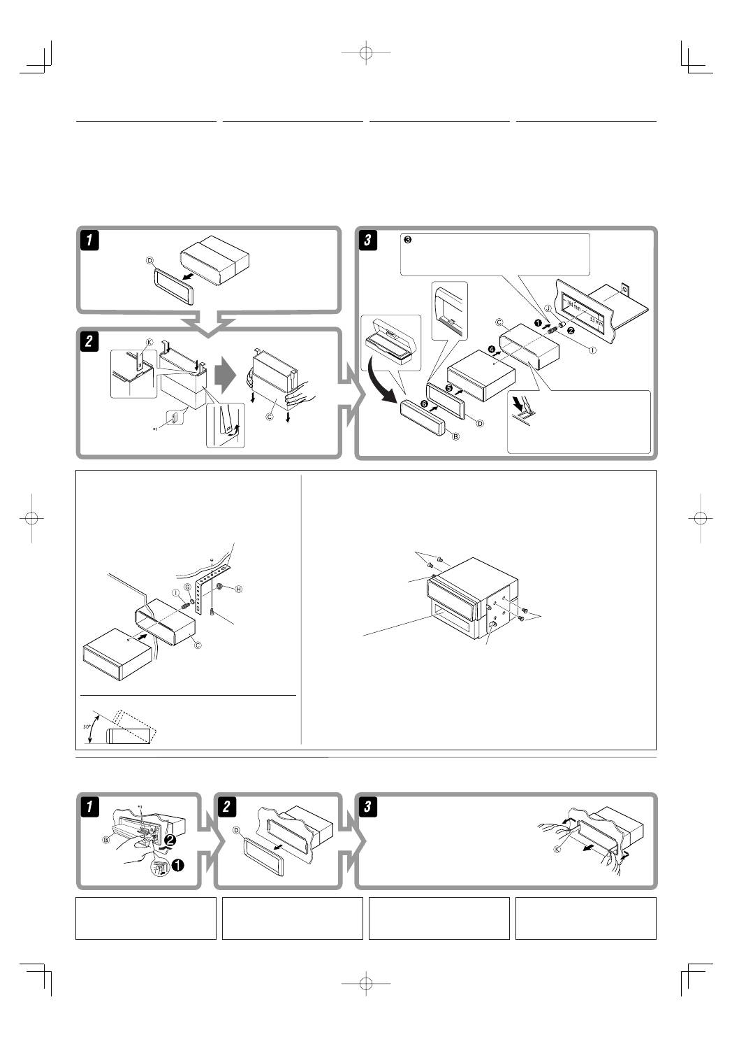
2
INSTALLATION (IN-DASH MOUNTING)
The following illustration shows a typical
installation. If you have any questions or require
information regarding installation kits, consult
your Kenwood Car Audio dealer or a company
supplying kits.
•
Make sure not to block the fan on the rear to
maintain proper ventilation when installing the
unit.
•
If you are not sure how to install this unit
correctly, have it installed by a qualified
technician.
EINBAU (IM ARMATURENBRETT)
Die folgende Abbildung zeigt einen typischen Einbau.
Wenn Sie weitere Fragen haben oder Informationen
zu Einbausätzen benötigen, wenden Sie sich an Ihren
Kenwood-Autoradiohändler oder an eine Bezugsquelle
für Einbausätze.
•
Sicherstellen, dass nicht das Gebläse an der
Rückseite verdeckt wird, um richtige Ventilation
beim Einbau der Einheit zu gewährleisten.
•
Sind Sie sich über den richtigen Einbau des Geräts
nicht sicher, lassen Sie es von einem qualifizierten
Techniker einbauen.
INSTALLAZIONE (MONTAGGIO SUL CRUSCOTTO)
La figura che segue rappresenta un’installazione
tipica. Per chiarimenti o informazioni relative ai kit
per l’installazione, rivolgersi al proprio rivenditore
di sistemi audio per auto Kenwood o all’azienda
fornitrice dei kit.
•
Assicurarsi di non bloccare il ventilatore
sul pannello posteriore per mantenere una
ventilazione corretta una volta effettuata
l’installazione.
•
Se necessario, fare effettuare l’installazione da un
tecnico qualificato.
Do the required electrical connections.
Nehmen Sie die erforderlichen elektrischen Anschlüsse vor.
Eseguire i necessari collegamenti elettrici.
Выполните необходимые подключения контактов, как
показано на оборотной стороне этой инструкции.
Bend the appropriate tabs to hold the sleeve
firmly in place.
Die geeigneten Zapfen biegen, um die
Manschette sicher festzuhalten.
Böj de flikar som ska hålla hylsan ordentligt på
plats.
Отогните соответствующие фиксаторы,
предназначенные для прочной установки
корпуса.
When using the optional stay / Beim Verwenden der
Anker-Option / Utilizzo del supporto opzionale / При
использовании дополнительной стойки
When installing the unit without using the sleeve / Beim Einbau des Geräts ohne
Halterung / Installazione dell’apparecchio senza protezione / При установке
устройства без использования муфты
In a Toyota car for example, first remove the car radio and install the unit in its place.
Zum Beispiel in einem Toyota zuerst das Autoradio ausbauen und dann das Gerät an seinem Platz einbauen.
Ad esempio, in una Toyota, si deve innanzi tutto togliere la radio ed installare poi l’apparecchio in suo luogo.
В автомобилях “Toyota”, например, сначала удалите автомобильную магнитолу, затем установите на ее место это устройство.
Screw (option)
Schraube (Option)
Vite (opzionale)
Винт (дополнительно)
Stay (option)
Anker (Option)
Supporto (opzionale)
Стойка (дополнительно)
Fire wall
Feuerwand
Parete antincendio
Стена
Dashboard
Armaturenbrett
Cruscotto
Приборная панель
Bracket
*
2
Konsole
*
2
Staffa
*
2
Кронштейн
*
2
Flat head screws (M5 × 8 mm)
*
2
Flachkopfschrauben (M5 × 8 mm)
*
2
Viti di fissaggio a testa piana (M5 × 8 mm)
*
2
Болты с плоской головкой (M5 × 8 мм)
*
2
Taschen
Tascabile
Карман
Flat head screws (M5
×
8 mm)
*
2
Flachkopfschrauben (M5
×
8 mm)
*
2
Viti di fissaggio a testa piana (M5 × 8 mm)
*
2
Болты с плоской головкой (M5 × 8 mm)
*
2
Bracket
*
2
Konsole
*
2
Staffa
*
2
Кронштейн
*
2
Note
:
When installing the unit on the mounting bracket, make sure to use the 8 mm-long screws. If longer screws
are used, they could damage the unit.
Hinweis
:
Beim Anbringen des Gerät an der Konsole sicherstellen, daß 8 mm lange Schrauben verwendet werden. Werden
längere Schrauben verwendet, können sie das Gerät beschädigen.
Nota
:
Durante l’installazione dell’apparecchio sulla staffa di montaggio, utilizzare esclusivamente le viti da 8 mm. Si
ricorda che l’uso di viti più lunghe potrebbe danneggiare l’apparecchio.
Примечание :
При установке устройства на крепежный кронштейн, используйте только винты длиной 8 мм. При
использовании более длинных винтов можно повредить устройство.
Removing the unit
Before removing the unit, release the rear section.
Insert the two handles, then pull them as illustrated
so that the unit can be removed.
Die beiden Handgriffe einsetzen und dann ziehen wie
in der Abbildung gezeigt, so daß das Gerät entfernt
werden kann.
För in de två handtagen, dra sedan i dem enligt
illustrationen så att apparaten kan förflyttas.
Вставьте два рычажка, затем потяните их, как
показано на рисунке, чтобы вынуть устройство.
Rimozione dell’apparecchio
Prima di rimuovere l’apparecchio, sganciare la parte
posteriore.
УСТАНОВКА (УСТАНОВКА В ПРИБОРНУЮ ПАНЕЛЬ)
На следующих иллюстрациях показана типовая
установка. Если у вас есть вопросы или вам
необходима информация относительно
инсталляционных комплектов, обратитесь
к своему дилеру аудиосистем Kenwood для
автомобилей или в фирму-поставщик комплектов.
•
При установке устройства для обеспечения
правильной вентиляции не закрывайте
вентилятор на задней панели.
•
Если Вы не знаете точно, как следует
устанавливать это устройство, обратитесь к
квалифицированному специалисту.
Ausbau des Geräts
Vor dem Ausbau des Geräts den hinteren Teil
freigeben.
Удаление устройства
Перед удалением устройства освободите заднюю
часть.
*
1
When you stand the unit, be careful not to damage
the fuse on the rear.
*
2
Not supplied for this unit.
*
3
Avoid touching the connector.
*
1
Beim Aufstellen des Geräts darauf achten, daß die
Sicherung auf der Rückseite nicht beschädigt wird.
*
2
Wird nicht mit Gerät mitgeliefert.
*
3
Berühren Sie nicht die Steckerkontakte.
*
1
Устанавливайте устройство таким образом, чтобы
не повредить предохранитель, расположенный
сзади.
*
2
не входит в комплект поставки
*
3
Не прикасайтесь к разъемам.
*
1
Nel posizionare l’apparecchio, fare attenzione a non
danneggiare il fusibile sul posteriore.
*
2
Non fornite con l’apparecchio.
*
3
Evitare di toccare i connettori.
Install the unit at an angle of less than 30˚.
Stellen Sie das Gerät mit einem Winkel von
weniger als 30˚ auf.
Installare l’unità a un’inclinazione inferiore a 30˚.
Установите устройство под углом менее 30°.
KDV-5241U̲install.indb 2
KDV-5241U̲install.indb 2
08.5.9 3:53:48 PM
08.5.9 3:53:48 PM
3
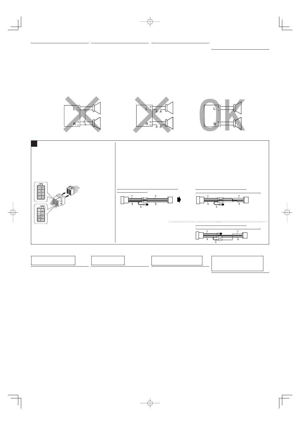
PRECAUTIONS on power supply
and speaker connections:
•
DO NOT connect the speaker leads of the
power cord to the car battery; otherwise, the
unit will be seriously damaged.
•
BEFORE connecting the speaker leads of the
power cord to the speakers, check the speaker
wiring in your car.
PRECAUZIONI! Collegamento
del cavo di alimentazione e delle
casse:
•
NON collegare i fili del cavo di alimentazione
per le casse alla batteria dell’auto perché
l’apparecchio ne verrebbe seriamente
danneggiato.
•
PRIMA di collegare i fili del cavo si alimentazione
per le casse alle casse stesse, verificare il relativo
cablaggio sulla vettura.
VORSICHTSMASSREGELN beim
Anschließen der Stromversorgung
und Lautsprecher:
•
Die Lautsprecherleitungen des Netzkabels
NICHT an der Autobatterie anschließen, da
sonst das Gerät schwer beschädigt wird.
•
VOR dem Anschließen der Lautsprecherleitungen
des Spannunsgversorgungskabels an die
Lautsprecher, die Lautsprecherverdrahtung in
Ihrem Auto überprüfen.
ПРЕДОСТЕРЕЖЕНИЯ по
питанию и подключению
громкоговорителей:
•
НЕ подключайте провода
громкоговорителей к аккумулятору
автомобиля, иначе устройство будет
повреждено.
•
ПЕРЕД подключением проводов
громкоговорителей к кабелю питания
громкоговорителя проверьте схему соединений
громкоговорителей в Вашем автомобиле.
TROUBLESHOOTING
•
The fuse blows.
*
Are the red and black leads connected correctly?
•
Power cannot be turned on.
*
Is the yellow lead connected?
•
No sound from the speakers.
*
Is the speaker output lead short-circuited?
•
Sound is distorted.
*
Is the speaker output lead grounded?
*
Are the “–” terminals of L and R speakers
grounded in common?
•
Noise interfere with sounds.
*
Is the rear ground terminal connected to the car’s
chassis using shorter and thicker cords?
•
This unit becomes hot.
*
Is the speaker output lead grounded?
*
Are the “–” terminals of L and R speakers
grounded in common?
•
This unit does not work at all.
*
Have you reset your unit?
FEHLERSUCHE
•
Die Sicherung brennt durch.
*
Sind die roten und schwarzen Leitungen richtig
angeschlossen?
•
Stromversorgung kann nicht eingeschaltet
werden.
*
Ist die gelbe Leitung angeschlossen?
•
Kein Ton aus den Lautsprechern.
*
Ist die Lautsprecherausgangsleitung
kurzgeschlossen?
•
Ton verzerrt.
*
Ist die Lautsprecherausgangsleitung geerdet?
*
Sind die „–“ Anschlußklemmen der linken und
rechten Lautsprecher zusammen geerdet?
•
Störgeräusche im Klang.
*
Ist die hintere Erdungsklemme mit kürzeren
und dickeren Kabeln an das Fahrzeugchassis
angeschlossen?
•
Gerät wird heiß.
*
Ist die Lautsprecherausgangsleitung geerdet?
*
Sind die „–“ Anschlußklemmen der linken und
rechten Lautsprecher zusammen geerdet?
•
Dieser Receiver funktioniert überhaupt nicht.
*
Haben Sie einen Reset am Receiver vorgenommen?
RICERCA GUASTI
•
Il fusibile brucia.
*
I fili rossi e neri sono stati collegati correttamente?
•
Non si riesce ad accendere l’apparecchio.
*
Il filo giallo è stato collegato?
•
Non esce alcun suono dalle casse.
*
Il filo di uscita delle casse è stato protetto contro i
cortocircuiti?
•
Suono distorto.
*
Il filo di uscita delle casse è collegato a terra?
*
I terminali “–” delle casse di sinistra e destra sono
stati collegati a terra in comune?
•
Vi sono interferenze nell’audio.
*
Il terminale a terra posteriore è collegato al telaio
dell’automobile per mezzo di cavi più corti e più
grossi?
•
L’apparecchio si surriscalda.
*
Il filo di uscita delle casse è collegato a terra?
*
I terminali “–” delle casse di sinistra e destra sono
stati collegati a terra in comune?
•
L’unità non funziona.
*
È stata inizializzata l’unità?
BЫЯВЛЕНИЕ НЕИСПРАВНОСТЕЙ
•
Сработал предохранитель.
* Правильно ли подключены черный и красный
провода?
•
Питание не включается.
* Подключен ли желтый провод?
•
Звук не выводится через
громкоговорители.
* Нет ли короткого замыкания на кабеле выхода
громкоговорителей?
•
Звук искажен.
* Заземлен ли провод выхода
громкоговорителей?
* Заземлены ли разъемы “–” правого (R) и левого
(L) громкоговорителей?
•
Шум мешает звучанию.
* Соединен ли находящийся сзади зажим
заземления с шасси автомобиля с помощью
более короткого и тонкого шнуров?
•
Устройство нагревается.
* Заземлен ли провод выхода
громкоговорителей?
* Заземлены ли разъемы “–” правого (R) и левого
(L) громкоговорителей?
•
Приемник не работает.
* Выполнена ли перенастройка приемника?
A
Y: Yellow
Gelb
Giallo
Желтый
R: Red
Rot
Rosso
Красный
If your car is equipped with the ISO
connector / Wenn Ihr Fahrzeug mit dem ISO-
Steckverbinder ausgestattet ist / Se la propria
auto dispone del connettore ISO / Если
автомобиль оснащен разъемом ISO
•
Connect the ISO connectors as illustrated.
•
Schließen Sie die ISO-Steckverbinder an, wie in der Abbildung gezeigt.
•
Collegare i connettori ISO come mostrato in figura.
•
Подключите разъемы ISO, как показано на рисунке.
From the car body
Von der Fahrzeugkarosserie
Dalla carrozzeria dell’auto
От корпуса автомобиля
ISO connector of the supplied power cord
ISO-Stecker des mitgelieferten Stromkabels
Connettore ISO del cavo di alimentazione fornito
Разъем ISO шнура питания, входящего в комплект
поставки
View from the lead side
Von der Kabelseite aus gesehen
Vista dal lato dei cavi
Вид со стороны выводов
For some VW/Audi or Opel (Vauxhall) automobile / Bei bestimmten VW-/Audi- order Opel-
(Vauxhall-) Fahrzeugen / Per alcune automobili VW/Audi o Opel (Vauxhall) / Для некоторых
автомобилей VW/Audi или Opel (Vauxhall)
You may need to modify the wiring of the supplied power cord as illustrated.
•
Contact your authorized car dealer before installing this unit.
Es kann erforderlich sein, die Verdrahtung des mitgelieferten Stromkabels zu modifizieren, wie in der Abbildung gezeigt.
•
Wenden Sie sich vor dem Einbau dieses Receivers an Ihre Auto-Fachwerkstatt.
Potrebbe essere necessario modificare il cablaggio del cavo di alimentazione fornito come illustrato.
•
Contattare il proprio rivenditore di automobili prima di installare questo ricevitore.
Возможно, потребуется изменить схему соединений для прилагаемого шнура питания, как показано на рисунке.
•
Перед установкой приемника обратитесь к авторизованному агенту по продажам автомобильных систем.
Original wiring /
Originalverdrahtung
/
Cablaggio originale
/
Исходная схема соединений
Modified wiring
1
/
Modifizierte Verdrahtung
1
/
Cablaggio modificato
1
/
Преобразованная схема соединений
1
Use modified wiring
2
if the unit does not turn on.
Verwenden Sie die modifizierte Verdrahtung
2
wenn der Receiver nicht einschaltet.
Utilizzare il cablaggio modificato
2
se il ricevitore non viene acceso.
Если приемник не включается, используйте преобразованную схему соединений
2
.
Modified wiring
2
/
Modifizierte Verdrahtung
2
/
Cablaggio modificato
2
/
Преобразованная схема соединений
2
ISO connector
ISO-Steckverbinder
Connettore ISO
Разъем ISO
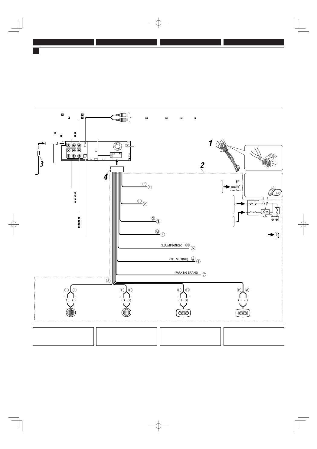
ELECTRICAL CONNECTIONS COLLEGAMENTI ELETTRICI
ЭЛЕКТРИЧЕСКИЕ ПОДКЛЮЧЕНИЯ
ELEKTRISCHE ANSCHLÜSSE
KDV-5241U̲install.indb 3
KDV-5241U̲install.indb 3
08.5.9 3:53:49 PM
08.5.9 3:53:49 PM
4
ENGLISH
ITALIANO
B
15 A fuse
15 A Sicherung
Fusibile 15 A
Предохранитель 15 A
Rear ground terminal
Hintere Erdungscan-schlußklemme
Terminale di terra posteriore
Задний разъем заземления
LINE OUT
(see diagram
/
siehe Schaltplan
/
cfr. schema
/
см. схему
)
Ignition switch
Zündschalter
Interruttore di accensione
Переключатель зажигания
Fuse block
Sicherungsblock
Blocco fusibili
Блок предохранителя
White with black stripe
Weiß mit schwarzem Streifen
Bianco a strisce nere
Белый с черной полосой
White
Weiß
Bianco
Белый
Gray with black stripe
Grau mit schwarzem Streifen
Grigio a strisce nere
Серый с черной полосой
Gray
Grau
Grigio
Серый
Green with black stripe
Grün mit schwarzem Streifen
Verde a strisce nere
Зеленый с черной полосой
Green
Grün
Verde
Зеленый
Purple with black stripe
Lila mit schwarzem Streifen
Porpora a strisce nere
Пурпурный с черной полосой
Purple
Lila
Porpora
Пурпурный
Left speaker (front)
Linker Lautsprecher (vorne)
Cassa sinistra (anteriore)
Левый громкоговоритель (передний)
Right speaker (front)
Rechter Lautsprecher (vorne)
Cassa destra (anteriore)
Правый громкоговоритель (передний)
Left speaker (rear)
Linker Lautsprecher (hinten)
Cassa sinistra (posteriore)
Левый громкоговоритель (задний)
Right speaker (rear)
Rechter Lautsprecher (hinten)
Cassa destra (posteriore)
Правый громкоговоритель
(задний)
To metallic body or chassis of the car
Zur metallenen Karosserie oder zum Fahrwerk des Autos
Sulla carrozzeria metallica o sul telaio dell’auto
К металлическому корпусу или шасси автомобиля
To a live terminal in the fuse block connecting to the car battery
(bypassing the ignition switch) (constant 12 V)
Zur einer stromführenden Anschlußklemme im Sicherungsblock zum
Anschließen an die Autobatterie (Umgehen des Zündschalters) (konstant 12 V)
Su un terminale sotto tensione nel blocco fusibili che si collega alla batteria dell’auto
(bypassando l’interruttore di accensione) (12 V costanti)
К разъему фазы в блоке предохранителя (минуя блок зажигания) (постоянный 12 В)
To an accessory terminal in the fuse block
Zur einer Zubehöranschlußklemme im Sicherungsblock
Su un terminale per accessori nel blocco fusibili
К вспомогательному разъему в блоке предохранителя
To the power control lead of other equipment or power aerial if any (200 mA max.)
Zum Leistungsreglerkabel des anderen Geräts oder zur Antenne, sofern vorhanden (max. 200 mA)
Al cavo di controllo dell’alimentazione di un’altra apparecchiatura o al cavo aereo, se presente (max 200 mA)
К блоку управления питанием другого оборудования или силовой антенне, если есть (макс. 200 мА)
Black
Schwarz
Nero
Черный
Yellow
*
2
Gelb
*
2
Giallo
*
2
Желтый
*
2
Red
Rot
Rosso
Красный
Blue with white stripe
Blau mit weißem Streifen
Blu a strisce bianche
Синий с белой полосой
Brown
Braun
Marrone
Коричневый
LINE IN
(see diagram
/
siehe Schaltplan
/
cfr. schema
/
см. схему
)
VIDEO OUT
(see diagram /
siehe Schaltplan
/
cfr. schema
/
см. схему
)
DEUTSCH
РУCCKИЙ
Connections without using the ISO connectors / Anschlüsse ohne Verwendung der ISO-Steckverbinder / Collegamenti senza utilizzare i
connettori ISO / Подключение без использования разъемов ISO
Before connecting:
Check the wiring in the
vehicle carefully.
The leads of the power cord and those of the
connector from the car body may be different in
color.
1
Cut the ISO connector.
2
Connect the colored leads of the power cord in
the order specified in the illustration below.
3
Connect the aerial cord.
4
Finally connect the wiring harness to the unit.
Vor dem Anschließen:
Die Verdrahtung im
Fahrzeug sorgfältig überprüfen.
Die Leiter des Stromkabels und die Leiter des
Anschlusses im Fahrzeug können sich farblich
unterscheiden.
1
Schneiden Sie den ISO-Steckverbinder auf.
2
Die farbigen Adern des Stromkabels in der
Reihenfolge anschließen, wie in der Abbildung
unten gezeigt.
3
Das Antennenkabel anschließen.
4
Die Kabelbäume am Gerät anschließen.
Prima del collegamento:
Verificare attentamente
il cablaggio della vettura.
I conduttori del cavo di alimentazione e quelli del
connettore sulla carrozzeria potrebbero essere di
colore diverso.
1
Tagliare il connettore ISO.
2
Collegare I conduttori colorati del cavo di
alimentazione nell’ordine indicato nella figura di
seguito.
3
Collegare il cavo dell’antenna.
4
Infine, collegare i cablaggi all’apparecchio.
Перед началом подключений:
Тщательно
проверьте проводку в автомобиле.
Неправильное подключение может привести к
серьезному повреждению устройства.
Жилы силового кабеля и жилы соединителя от
кузова автомобиля могут быть разного цвета.
1
Обрежьте разъем ISO.
2
Подсоедините цветные провода шнура
питания в указанном ниже порядке.
3
Подключите кабель антенны.
4
В последнюю очередь подключите
электропроводку к устройству.
To cellular phone system
An Mobiltelefonsystem
Al sistema per telefono cellulare
К системе сотового телефона
To parking brake, metallic body or chassis of the car
Zur Handbremse, zur Metallkarosserie oder zum Chassis des Fahrzeugs
Freno a mano, carrozzeria o chassis dell’auto
К стояночному тормозу, корпусу или ходовой части автомобиля
*
1
Wird nicht mit Gerät mitgeliefert.
*
2
Vor der Überprüfung der Funktionsfähigkeit
des Geräts vor dem Einbau, muß diese Leitung
angeschlossen werden, da sonst die Stromversorgung
nicht eingeschaltet werden kann.
*
1
Not supplied for this unit.
*
2
Before checking the operation of this unit prior to
installation, this lead must be connected, otherwise
power cannot be turned on.
*
1
Не входит в комплект поставки.
*
2
Перед проверкой работы устройства подключите
этот провод, иначе питание не включится.
Aerial connector
Antennenanschluss
Connettore dell’antenna
Разъем антенны
SW
(Subwoofer/
Subwoofer
/
Subwoofer
/
Низкочастотный динамик
)
(see diagram
/
siehe Schaltplan
/
cfr. schema
/
см. схему
)
Orange with white stripe
Orange mit weißem Streifen
Arancione con striscia biancae
Оранжевый с белой полосой
To car light control switch
Zum Autobeleuchtungssteuerung-Schalter
All’interruttore di comando delle luci del veicolo
К контрольному переключателю освещения автомобиля
Light green
Hellgrün
Spia verde
Зеленого цвета
2nd AUDIO OUT
(see diagram /
siehe Schaltplan
/
cfr. schema
/
см. схему
)
Do not connect. /
Nicht anschließen.
/
Non collegare. /
Не подключать.
*
1
Non fornito con l’apparecchio.
*
2
Per poter verificare il funzionamento
dell’apparecchio prima dell’installazione, è
necessario avere già collegato questo filo (altrimenti
è impossibile accendere l’apparecchio).
KDV-5241U̲install.indb 4
KDV-5241U̲install.indb 4
08.5.9 3:53:50 PM
08.5.9 3:53:50 PM
C
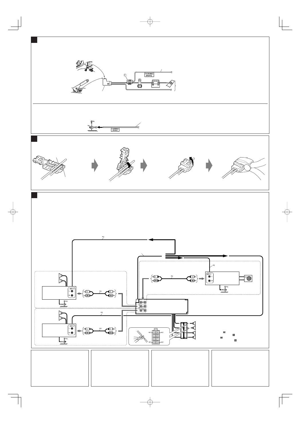
Connecting the parking brake wire / Anschluss des Handbremsenkabels / Collegamento del filo del freno a mano / Подключение провода
стояночного тормоза
When installing the monitor in a location
where it can be seen by the driver
Connect the parking brake wire to the parking
brake system built in the car.
When installing the monitor in a location
where it cannot be seen by the driver
Connect the parking brake wire to metallic body
or chassis of the car.
Connecting the crimp connector / Anschließen des Crimpanschlusses / Collegamento del connettore del freno / Подключение обжимного
разъема
D
Installazione del monitor in un punto visibile
al conducente
Collegare il filo del freno a mano al sistema del freno
a mano incorporato nell’auto.
Parking brake wire (light green)
Handbremsenkabel (hellgrün)
Filo del freno a mano (spia verde verde)
Провод стояночного тормоза (зеленого цвета)
To metallic body or chassis of the car
Zur metallenen Karosserie oder zum Fahrwerk des Autos
Sulla carrozzeria metallica o sul telaio dell’auto
К металлическому корпусу или шасси автомобиля
Parking brake switch (inside the car)
Handbremsenschalter (Fahrzeuginneres)
Commutatore del freno a mano (all’interno della macchina)
Переключатель стояночного тормоза (внутри автомобиля)
Parking brake
Handbremse
Freno a mano
Стояночный тормоз
Wenn der Monitor an einer vom Fahrer nicht
einsehbaren Stelle installiert wird
Schließen Sie das Handbremsenkabel an die
Metallkarosserie oder an das Chassis des Fahrzeugs
an.
Installazione del monitor in un punto non
visibile al conducente
Collegare il filo del freno a mano alla carrozzeria o
allo chassis dell’auto.
Parking brake wire (light green)
Handbremsenkabel (hellgrün)
Filo del freno a mano (spia verde)
Провод стояночного тормоза (зеленого цвета)
Wire connecting the battery and the parking brake switch.
Verbinden des Batterie- und des Handbremsenkabelschalters.
Fissare il filo del freno a mano a questo punto.
Подключить провод стояночного тормоза к этой точке.
Attach the parking brake wire to this point.
Legen Sie das Handbremsenkabel hier ein.
Filo che collega la batteria e il commutatore del freno a mano.
Провод, соединяющий аккумулятор и включатель стояночного тормоза.
Contact the metallic part of the crimp to the wires inside.
Kontaktieren des Metallteils des Quetschverbinders mit den Kabeln im
Inneren.
Mettere in contatto la parte metallica della pinza crimpatrice ai fili interni.
Присоедините металлическую часть обжимного соединителя к
находящимся внутри проводам.
Wenn der Monitor an einer vom Fahrer
einsehbaren Stelle installiert wird
Anschluss des Handbremsenkabels an das im
Fahrzeug eingebaute Handbremsensystem.
При установке монитора в месте, видном
водителю
Подключить провод стояночного тормоза к
проводке стояночного тормоза автомобиля.
При установке монитора в месте, не
видном водителю
Подключить провод стояночного тормоза к
металлу корпуса или ходовой части автомобиля.
Pinch the crimp firmly.
Drücken Sie den Quetschverbinder fest
zusammen.
Stringere forte la pinza crimpatrice.
Плотно обожмите соединитель.
{
KDV-5241U
Connecting the external amplifiers and subwoofer / Anschließen der externen Verstärker und Subwoofer / Collegamento di amplificatori e
subwoofer esterni / Подключение внешних усилителей и низкочастотного динамика
You can connect amplifiers to upgrade your car
stereo system.
• Connect the power control lead (blue with
white stripe) to the power control lead of the
other equipment so that it can be controlled
through this unit.
• Disconnect the speakers from this unit,
connect them to the amplifier. Leave the
speaker leads of this unit unused.
E
Sie können Verstärker anschließen, um Ihre
Autostereoanlage zu erweitern.
• Schließen Sie das Leistungsreglerkabel (blau mit
weißem Streifen) an das Leistungsreglerkabel des
anderen Gerätes an, so dass dieses von Ihrem
Gerät aus gesteuert werden kann.
• Die Lautsprecher von diesem Gerät abtrennen
und am Verstärker anschließen. Die
Lautsprecherleitungen dieses Geräts unbenutzt
lassen.
È possibile potenziare l’impianto stereo dell’auto
collegando degli amplificatori.
• Collegare il cavo di controllo dell’alimentazione
(blu a strisce bianche) al cavo di controllo
dell’alimentazione dell’altra apparecchiatura,
in modo che questa possa essere controllata
attraverso la presente unità.
• Scollegare le casse dall’apparecchio e collegarle
all’amplificatore. Non utilizzare i contatti delle
casse dell’apparecchio.
Rear speakers
Hintere Lautsprecher
Casse posteriori
Задние
громкоговорители
Amplifier
Verstärker
Amplificatore
Усилитель
Power control lead (blue with white stripe)
Leistungsreglerkabel (blau mit weißem Streifen)
Cavo di controllo dell’alimentazione (blu a strisce bianche)
Силовой кабель (синий с белой полосой)
Front speakers (see diagram )
Vordere Lautsprecher (siehe Schaltplan )
Casse frontali (cfr. schema )
Передние громкоговорители (см. схему )
Rear speakers
Hintere Lautsprecher
Casse posteriori
Задние громкоговорители
*
3
Power control lead
*
4
Not supplied for this unit.
*
5
Signal cord (not supplied for this unit)
*
6
Firmly attach the ground wire to the metallic body
or to the chassis of the car—to the place uncoated
with paint (if coated with paint, remove the paint
before attaching the wire). Failure to do so may
cause damage to the unit.
*
7
Cut the rear speaker leads of the car’s ISO
connector and connect them to the amplifier.
*
3
Cavo di controllo dell’alimentazione
*
4
Non fornite con l’apparecchio.
*
5
Cavo dei segnali (non fornito con l’apparecchio)
*
6
Fissare saldamente il filo di terra alla carrozzeria
o al telaio dell’ auto—in un punto non verniciato
(dovendo fissare il filo ad un punto verniciato,
occorre provvedere alla preventiva sverniciatura,
altrimenti l’unità potrebbe danneggiarsi).
*
7
Tagliare i cavi degli altoparlanti posteriori
del connettore ISO dell’auto e collegarli
all’amplificatore.
*
3
Leistungsreglerkabel
*
4
Berühren Sie nicht die Steckerkontakte.
*
5
Einzelleitung (wird nicht mit Gerät mitgeliefert)
*
6
Verbinden Sie den Erdungsleiter mit der Karosserie
oder dem Rahmen des Fahrzeugs. Die Kontaktstelle
darf nicht lackiert sein (sollte die Kontaktstelle lackiert
sein, entfernen Sie den Lack der Kontaktstelle, bevor Sie
den Leiter befestigen). Wenn der Erdungsleiter nicht
ordnungsgemäß angeschlossen wird, kann dieses Gerät
beschädigt werden.
*
7
Schneiden Sie die hinteren Lautsprecherkabel des ISO-
Steckverbinders des Fahrzeugs ab, und schließen diese
an den Verstärker an.
Amplifier
Verstärker
Amplificatore
Усилитель
Front speakers
Vordere Lautsprecher
Casse frontali
Передние
громкоговорители
Amplifier
Verstärker
Amplificatore
Усилитель
Subwoofer
Subwoofer
Subwoofer
Низкочастотный
динамик
Можно подключить усилители для обновления
автомобильной стереосистемы.
•
Подсоедините силовой кабель (синий с
белой полоской) к силовому кабелю другого
оборудования для возможности управления с
данного устройства.
•
Отсоедините громкоговорители от данного
устройства, подключите их к усилителю.
Оставьте провода громкоговорителей
данного устройства неиспользованными.
*
3
Силовой кабель
*
4
Не входит в комплект поставки.
*
5
Кабель сигнала (не входит в комплект поставки).
*
6
Плотно прикрепите заземляющий провод к
металлическому кузову или шасси автомобиля—
в месте, не покрытом краской (если оно
покрыто краской, удалите краску перед тем,
как прикреплять провод). Невыполнение этого
требования может привести к повреждению
данного устройства.
*
7
Обрежьте выводы задних динамиков для
разъема ISO автомобиля и подсоедините их к
усилителю.
5
KDV-5241U̲install.indb 5
KDV-5241U̲install.indb 5
08.5.9 3:53:51 PM
08.5.9 3:53:51 PM
6
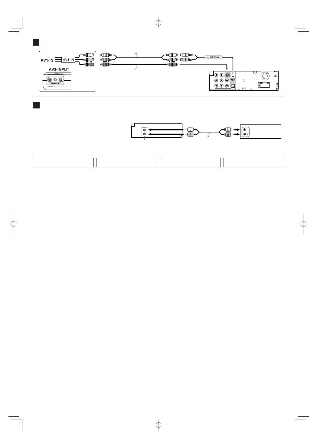
Required connections for DVD/AV-IN (video) playback / Erforderliche Verbindungen für DVD/AV-IN (Video)-Wiedergabe / Collegamenti
richiesti per la riproduzione DVD/AV-IN (video) / Необходимые подключения для воспроизведения DVD/AV-IN (видео)
F
KDV-5241U
Video cord
*
9
Videokabel
*
9
Cavo video
*
9
Видеошнур
*
9
Rear side
Rückseite
Lato posteriore
Задняя панель
*
8
Einzelleitung (wird nicht mit Gerät mitgeliefert)
*
9
Wird nicht mit Gerät mitgeliefert.
*
8
Cavo dei segnali (non fornito con l’apparecchio)
*
9
Non fornito con l’apparecchio.
G
Connecting the external components / Anschließen der externen Komponenten / Collegamento dei componenti esterni / Подключение
внешних устройств
You can also connect an external component to the LINE IN terminals on the
rear of the unit using a signal cord (not supplied).
Sie können auch eine externe Komponente an die Klemmen LINE IN an der
Rückseite der Einheit mit einem Signalkabel (nicht mitgeliefert) anschließen.
È possibile inoltre collegare un componente esterno ai terminali LINE IN
sul pannello posteriore dell’unità per mezzo di un cavo di segnale (non in
dotazione).
Внешнее устройство можно подсоединить к разъемам LINE IN на задней
панели устройства с помощью сигнального кабеля (не входит в комплект
поставки).
KDV-5241U
or /
oder
/
ooppure
/
или
LINE IN terminals /
LINE IN-Klemmen
/
Terminali LINE IN
/
Терминалы LINE IN
External component
Externe Komponente
Componente esterno
Внешнее устройство
*
8
Signal cord (not supplied for this unit)
*
9
Not supplied for this unit.
*
8
Кабель сигнала (не входит в комплект поставки)
*
9
Не входит в комплект поставки.
KDV-5241U̲install.indb 6
KDV-5241U̲install.indb 6
08.5.9 3:53:52 PM
08.5.9 3:53:52 PM
