Kenwood KTC-V301E: инструкция
Раздел: Мультимедиа
Тип:
Инструкция к Kenwood KTC-V301E

KTC-V301E
TV TUNER 3 page 2 - 9
INSTRUCTION MANUAL
TV-TUNER 3 Seite 10 - 17
BEDIENUNGSANLEITUNG
SINTONIZZATORE TV 3 pagina 18 - 25
ISTRUZIONI PER L'USO
SINTONIZADOR TV 3 página 26 - 33
MANUAL DE INSTRUCCIONES
SINTONIZADOR TV 3 página 34 - 41
MANUAL DE INSTRUÇÕES
ТВ-ТЮНЕР 3 page 42 - 49
ИHCTPУKCИЯ ПO ЭKCПЛУATAЦИИ
ТВ-ТЮНЕР 3 page 50 - 56
ІНСТРУКЦІЯ З ВИКОРИСТАННЯ
SI DICHIARA CHE:
Il Sintonizzatore TV Kenwood per auto, modello KTC-V301E risponde alle
prescrizioni dell'art. 2 comma 1 del D.M. 28 agosto 1995, n. 548.
Fatto ad Uithoorn il 13 maggio 2008
Kenwood Electronics Europe B.V.
Amsterdamseweg 37
1422 AC Uithoorn
The Netherlands
Сделано в Китае
© B64-4243-00/00 (EV)
B64-4243-00KTC-V301E.indb1B64-4243-00KTC-V301E.indb1 08.7.2910:30:47AM08.7.2910:30:47AM

Before installation
Connectable Control unit
• If the ambient temperature is low, warm the glass
before starting the work.
• DNX8220BT
• Before starting the work, confirm well the places
• DNX7220
where the film antennas (Accessory 1 and 2) and
• DNX5220BT
the cables (Accessory 3 and 4) are to be installed.
• DNX5220
Once peeled off, the film antennas and double-stick
• DDX8022BT, DDX8022BTY
tape lose adhesion.
• DDX5022, DDX5022Y
• Do not fold or damage the film antennas.
• DDX52RT
• Noise generated by the air conditioner or monitor
• KVT-522DVD, KVT-522DVDY
can cause poor TV reception.
• KVT-50DVDRY
• The film antennas cannot be installed depending on
the vehicle model.
(As of July, 2008)
• The reception sensitivity can vary with the
windshield wiper operation depending on the
Before installing the antenna
vehicle model.
• The reception sensitivity can vary depending on the
2WARNING
relationship between the traveling direction of the
• Mounting and wiring this product requires skills and
vehicle (the pointing direction of the antennas) and
experience. For safety's sake, leave the mounting
the location of the broadcast station.
and wiring work to professionals.
2CAUTION
• In-car antennas have a lower reception sensitivity
than antennas intended for outside mounting. The
picture may not appear or may be disturbed if the
signal in your area is weak.
• The film antennas are designed specially for use in
car.
• Do not attach the film antennas in the following
places:
– A place where the driver’s view is blocked
– A place where safety parts such as an airbag are
prevented from operating normally
– On the surface of a glass such as a rear hatch glass
which is frequently moved
• The reception sensitivity lowers in the following
places:
– A place where a heat reflection glass or mirror-
type glass film is affixed
– A place where the film antenna of the factory-
supplied radio already exists
– On the window where the heating wire already
exists
– On the side of the vehicle (door, front quarter
window, etc.)
– On the rear window
– On a glass (heat reflecting glass, heat insulating
glass, etc.) that blocks radio waves
• Using the cleaner (Accessory 0), remove oil and dirt
from the glass surface to which the film antennas
are to be affixed.
2
|
KTC-V301E
B64-4243-00KTC-V301E.indb2B64-4243-00KTC-V301E.indb2 08.7.2910:30:49AM08.7.2910:30:49AM
Accessories
1
6
..........1
(3.0m) ..........1
2
7
..........1
..........2
3
8
(4.0m) ..........1
(M4x8mm) ..........4
4
9
(5.5m) ..........1
(ø4x16mm) ..........4
5
0
..........6
..........1
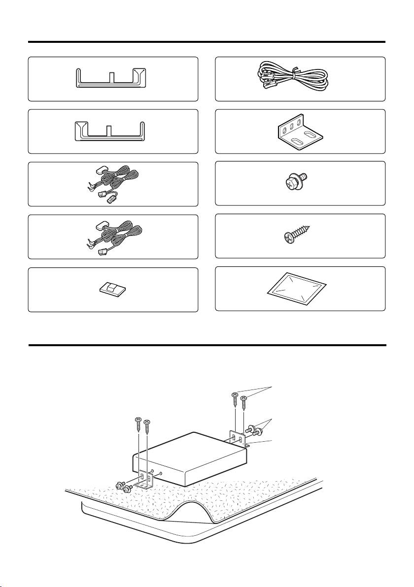
Installing the TV Tuner Unit
■ Securing to audio board
Use screws (Accessory 8 and 9) to fix TV Tuner onto an audio board or another.
Accessory 9
Accessory 8
Accessory 7
English
|
3
B64-4243-00KTC-V301E.indb3B64-4243-00KTC-V301E.indb3 08.7.2910:30:49AM08.7.2910:30:49AM

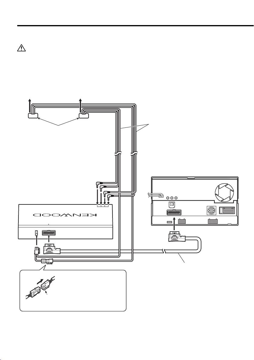
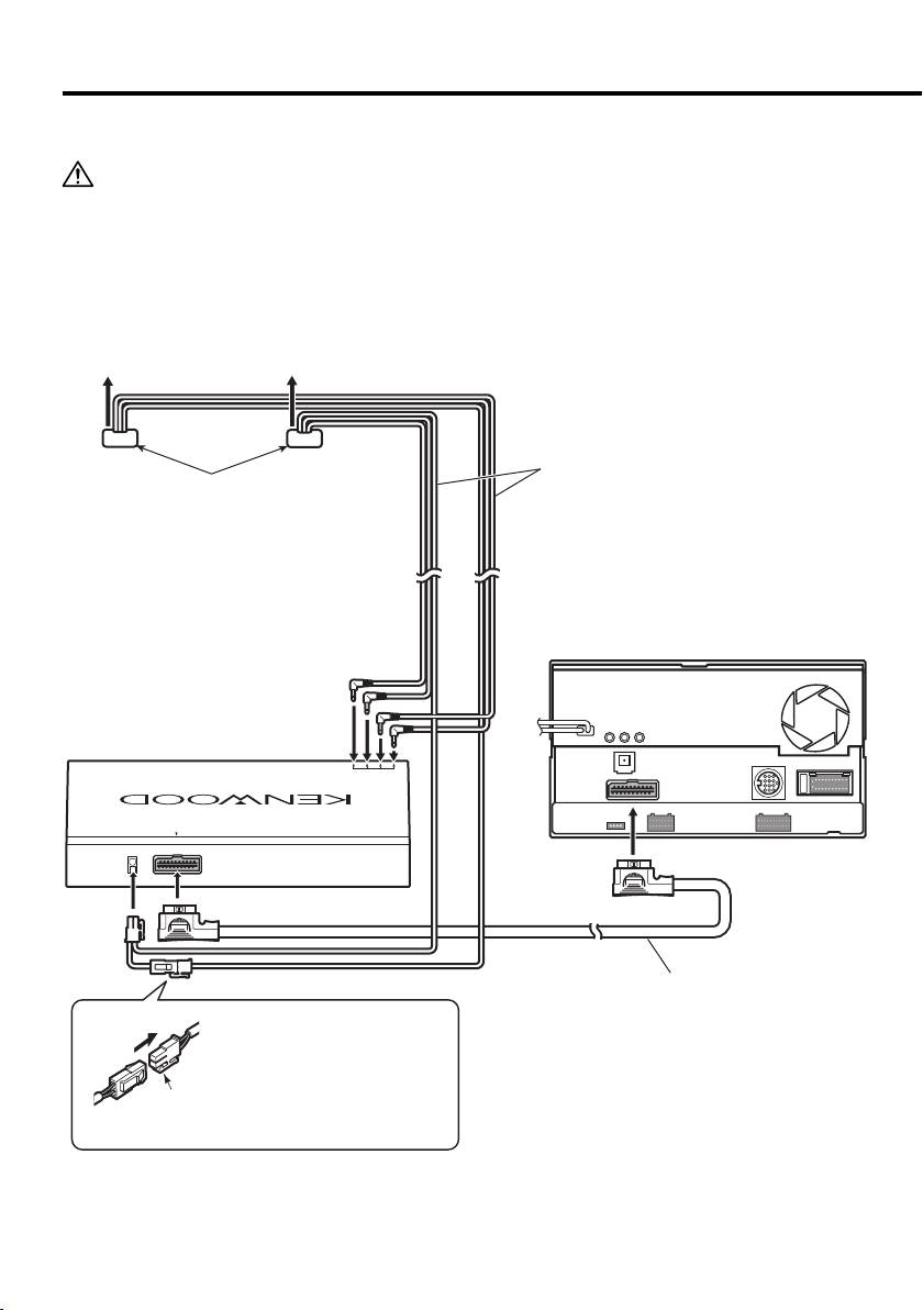
Installing the Antenna
■ System connection
• To prevent short circuits, remove the key from the ignition and disconnect the - terminal of the battery.
• Make sure to ground the unit to a negative 12V DC power supply.
• After the unit is installed, check whether the brake lamps, blinkers, wipers, etc. on the car are working
properly.
• Thoroughly wipe away oil and other dirt from the installation surface. Please avoid installation on uneven
surfaces.
To film antenna
To film antenna
TV antenna cable
(Accessory 3 and 4)
Both the left and right cable connectors are
adhesive-backed.
Control unit
TV tuner (KTC-V301E)
TV ANTENNA INPUT
TO MONITOR
Monitor cable
(Accessory 6)
• Insert the connector with the
hook aligned until it clicks.
• Release the hook when
Hook
disconnecting the connector.
4
|
KTC-V301E
B64-4243-00KTC-V301E.indb4B64-4243-00KTC-V301E.indb4 08.7.2910:30:50AM08.7.2910:30:50AM

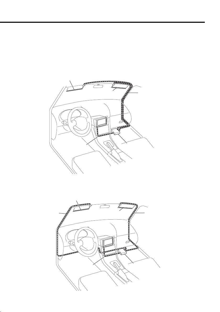
■ Wiring example
Select either one of the following wiring routes depending on the situation.
TV antenna cables (Accessory 3 and Accessory 4) are different in length. Use them appropriately to fit the
wiring of the vehicle you are working on.
Example A
This example shows a case where the cables are routed on the passenger’s seat side. For the right-hand-drive
car, route the cables on the left side passenger’s seat.
Film antenna
(Accessory 1)
Film antenna
TV antenna cable
(Accessory 2)
(Accessory 3 and 4)
Monitor cable
TV Tuner
(Accessory 6)
(KTC-V301E)
Example B
This example shows a case where it is difficult to route the cables near the rearview mirror.
Film antenna
(Accessory 1)
TV antenna cable
Film antenna
TV antenna cable
(Accessory 3 or 4)
(Accessory 2)
(Accessory 3 or 4)
Monitor cable
TV Tuner
(Accessory 6)
(KTC-V301E)
English
|
5
B64-4243-00KTC-V301E.indb5B64-4243-00KTC-V301E.indb5 08.7.2910:30:50AM08.7.2910:30:50AM
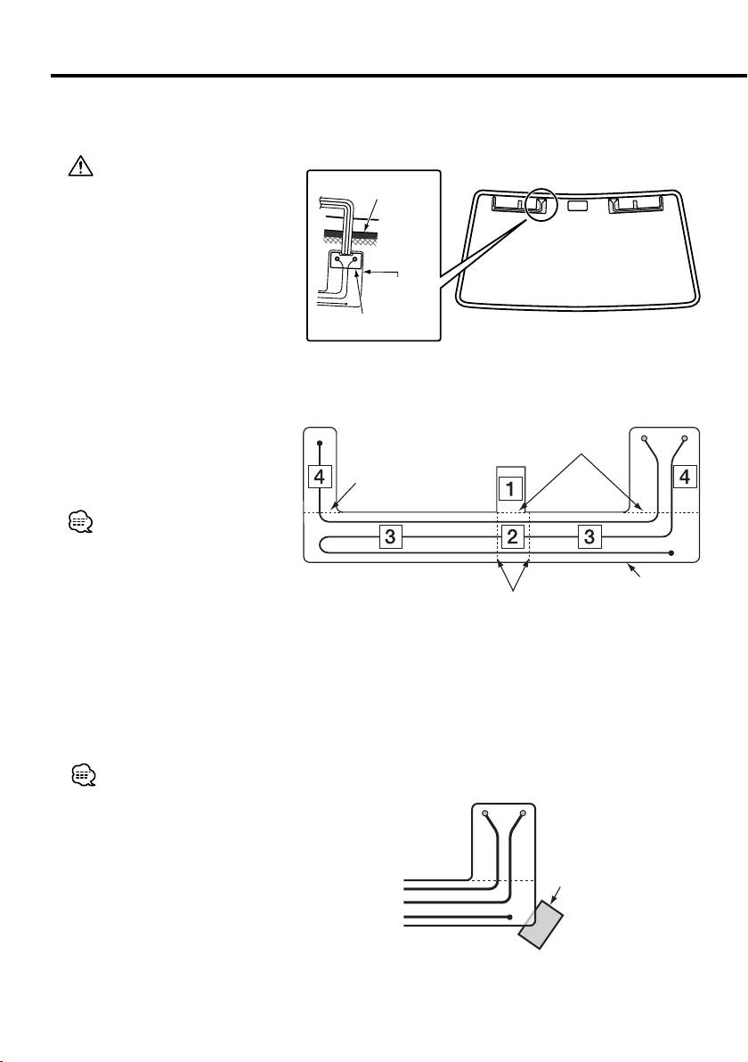
Installing the Antenna
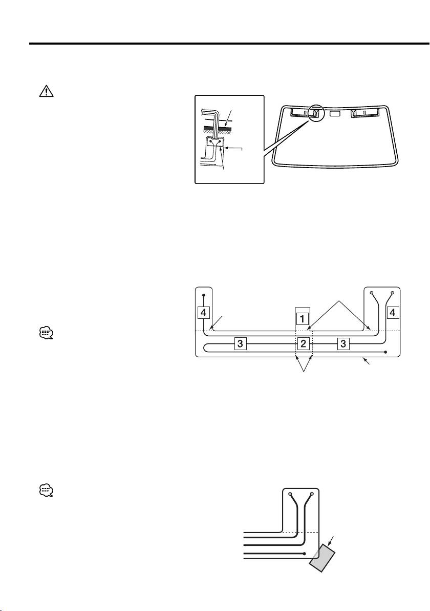
■ Installation Procedure
1. Confirm the installation place.
Ceramic line
• Affix the film antennas and cable
connectors to the front windshield
following the laws and regulations of
your country.
• Affix each film antenna so that it does
not overlap the ceramic line. Affixing
Film antenna
the antenna on the ceramic line will
lose the adhesion force.
Cable connector
Viewed from inside the vehicle
2. Using the cleaner (Accessory
0), wipe dirt off the antenna
installation surface.
3. Affix each film antenna.
1) Peel off the release paper (half-
Slit
transparent sheet) 1 starting at the
slit, and then affix the film antenna to
Slit
the windshield.
• Once peeled off, the remaining
portions of the antenna cannot be
affixed again. Confirm the installation
Film antenna
place again.
Slit
(Accessory 1)
2) Peel off the release paper 2 starting
at either slit, and affix the film antenna
to the windshield.
3) Peel off the release paper 3 and
release paper 4 and affix the film
antenna to the windshield in the
same manner as above.
• Either the left or right side of the film
antenna can be affixed first.
• Inserting the release paper 1 under
the corner of the film antenna as
shown on the right allows you to peel
Release paper 1
off other sheets of release paper easily.
6
|
KTC-V301E
B64-4243-00KTC-V301E.indb6B64-4243-00KTC-V301E.indb6 08.7.2910:30:51AM08.7.2910:30:51AM
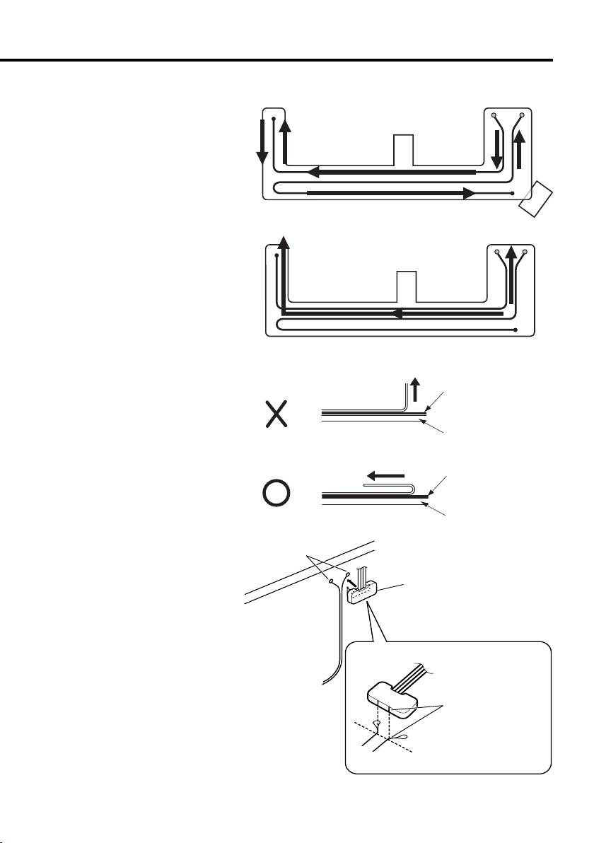
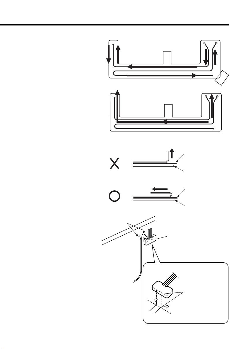
4. Rub a rubber spatula against the
transparent sheet to affix the
Rubbing directions and places
antenna element to the windshield
tightly. If the rubber spatula is
not available, use a small board
wrapped with cloth.
5. Slowly peel off the transparent
sheet along the element line.
Peel-off direction
Inside the
Antenna element
vehicle
Outside the vehicle
Windshield
Peel-off direction
Inside the
Antenna element
vehicle
Outside the vehicle
Windshield
6. Make sure that the antenna element
has been affixed tightly, and then
Element terminal
affix the cable connector to the
element terminal.
Cable connector
(Accessory 3 and 4)
7. Route the cable and secure it
Affix the cable connector
in such a manner that
with the supplied cable clamps
the bare portions of the
(Accessory 5).
antenna element are
aligned with the line
shape protrusions of the
cable connector.
English
|
7
B64-4243-00KTC-V301E.indb7B64-4243-00KTC-V301E.indb7 08.7.2910:30:51AM08.7.2910:30:51AM

Specifications
TV Tuner section
Colour system
: PAL/SECAM
Channel selection system
: PLL frequency synthesiser system
Television system
: PAL-B/G, PAL-I, SECAM-D/K, SECAM-B/G
Channel converge
VHF
(PAL-B/G) : 2 - 12 ch/ A - H2 ch
(PAL-I) : A - J ch
(SECAM-D/K) : 1 - 12 ch
(SECAM-B/G) : 2 - 12 ch
UHF : 21 - 69 ch
Demodulation system
: Split carrier system
Antenna input
: 4-ch diversity (3.5 ø miniplug)
General
Operating voltage
: 14.4 V DC (11 V - 16 V)
Current consumption
: 305 mA
Dimensions (W×H×D)
: 188 × 30 × 144 mm
Operational temperature range
: -10 °C - +60 °C
Storage temperature range
: -30 °C - +85 °C
Weight
: 680 g
TV Antenna
Output impedance
: 75 Ω /3.5 ø minijack
Operating voltage
: 8 V DC
Current consumption
: 85 mA
Cable length
: 4.0 m, 5.5 m
Film antenna element size (W×H)
: 345 × 94 mm
Weight
: 375 g
Specifications subject to change without notice.
8
|
KTC-V301E
B64-4243-00KTC-V301E.indb8B64-4243-00KTC-V301E.indb8 08.7.2910:30:52AM08.7.2910:30:52AM

This Product is not installed by the manufacturer of a
vehicle on the production line, nor by the professional
importer of a vehicle into an EU Member State.
Information on Disposal of Old Electrical
and Electronic Equipment and Batteries
(applicable for EU countries that have
adopted separate waste collection systems)
Products and batteries with the symbol
(crossed-out wheeled bin) cannot be
disposed as household waste.
Old electrical and electronic equipment
and batteries should be recycled at a facility
capable of handling these items and their
waste byproducts.
Contact your local authority for details in
locating a recycle facility nearest to you.
Proper recycling and waste disposal will
help conserve resources whilst preventing
detrimental effects on our health and the
environment.
Notice: The sign “Pb” below the symbol for
batteries indicates that this battery
contains lead.
Declaration of Conformity with regard to
the EMC Directive 2004/108/EC
Manufacturer:
Kenwood Corporation
2967-3 Ishikawa-machi, Hachioji-shi, Tokyo, 192-8525 Japan
EU Representative's:
Kenwood Electronics Europe BV
Amsterdamseweg 37, 1422 AC UITHOORN, The Netherlands
English
|
9
B64-4243-00KTC-V301E.indb9B64-4243-00KTC-V301E.indb9 08.7.2910:30:52AM08.7.2910:30:52AM

Vor der Installation
Anzuschließende Steuergeräte
– auf Glas, das Funkwellen blockiert
(hitzereflektierendes Glas, wärmeisolierendes Glas
• DNX8220BT
o. Ä.).
• DNX7220
• Entfernen Sie unter Verwendung des Reinigers
• DNX5220BT
(Zubehör 0) Öl und Verschmutzungen von der
• DNX5220
Glasoberfläche, an der die Filmantennen angebracht
• DDX8022BT, DDX8022BTY
werden sollen.
• DDX5022, DDX5022Y
• Falls die Umgebungstemperatur niedrig ist,
erwärmen Sie das Glas, bevor Sie mit der Arbeit
• DDX52RT
beginnen.
• KVT-522DVD, KVT-522DVDY
• Stellen Sie vor der Arbeit sicher, dass die jeweiligen
• KVT-50DVDRY
Stellen für die Installation der Filmantennen
(Stand: Juli 2008)
(Zubehör 1 und 2) und der Kabel (Zubehör 3
und 4) geeignet sind.
Vor der Installation der Antenne
Wenn die Filmantennen nach dem Anbringen
wieder abgelöst werden, verliert das
2WARNUNG
Doppelklebeband seine Haftung.
• Die Montage sowie die Verkabelung dieses Gerätes
• Falten Sie die Filmantennen nicht zusammen und
macht besondere Fähigkeiten und Erfahrung
beschädigen Sie sie nicht.
erforderlich. Überlassen Sie die Arbeiten zur
• Durch die Klimaanlage oder den Monitor erzeugte
Montage und Verkabelung ausgewiesenem
Störungen können eine Beeinträchtigung des
Fachpersonal.
Fernsehempfangs zur Folge haben.
• Die Filmantennen lassen sich je nach
2ACHTUNG
Fahrzeugmodell u. U. nicht installieren.
• Fahrzeug-Innenantennen weisen eine niedrigere
• Die Empfangsempfindlichkeit variiert je
Empfangsempfindlichkeit auf als Antennen, die für
nach Fahrzeugmodell bei Betätigung der
eine Außenmontage bestimmt sind. Falls das Signal
Scheibenwischer an der Windschutzscheibe.
in Ihrem Bereich schwach ist, wird das Bild u. U.
• Die Empfangsempfindlichkeit variiert je nach
nicht angezeigt oder weist Störungen auf.
Verhältnis zwischen der Fahrzeug-Fahrtrichtung
• Die Filmantennen wurden speziell für die
(Ausrichtung der Antennen) und dem Ort des
Verwendung in einem Fahrzeug konzipiert.
sendenden Radiosenders.
• Bringen Sie die Filmantennen auf keinen Fall an
einer der folgenden Stellen an:
– an einem Ort, an dem sie die Sicht des Fahrers
behindern würden;
– an einem Ort, an dem die Sicherheitsausrüstung
des Fahrzeuges wie beispielsweise ein Airbag in
ihrem normalen Betrieb behindert werden würde;
– an einer Glasoberfläche wie beispielsweise an
de hinteren Scheiben, die häufig hoch- und
hinuntergelassen werden.
• An den folgenden Orten ist die
Empfangsempfindlichkeit reduziert:
– an einem Ort, an dem hitzereflektierendes Glas
oder Spiegelglas vorhanden ist;
– an einem Ort, an dem bereits eine Filmantenne
des werkseitig eingebauten Radios vorhanden ist;
– an einem Fenster, in das bereits ein Heizdraht
integriert ist;
– an der Außenseite de Fahrzeugs (Tür, Vorderfenster
o. Ä.);
– an der Heckscheibe;
10
|
KTC-V301E
B64-4243-00KTC-V301E.indb10B64-4243-00KTC-V301E.indb10 08.7.2910:30:53AM08.7.2910:30:53AM

Zubehör
1
6
..........1
(3,0m) ..........1
2
7
..........1
..........2
3
8
(4,0m) ..........1
(M4x8mm) ..........4
4
9
(5,5m) ..........1
(ø4x16mm) ..........4
5
0
..........6
..........1
Installation der Fernseh-Tuner-Einheit
■ Sicherung an einem Audioboard
Verwenden Sie die Schrauben (Zubehör 8 und 9), um den Fernseh-Tuner an einem Audioboard o. Ä.
anzubringen.
Zubehör 9
Zubehör 8
Zubehör 7
Deutsch
|
11
B64-4243-00KTC-V301E.indb11B64-4243-00KTC-V301E.indb11 08.7.2910:30:53AM08.7.2910:30:53AM
Installation der Antenne
■ System-Anschluss
• Ziehen Sie den Zündschlüssel ab und trennen Sie den Minuspol von der Batterie ab, um Kurzschlüsse zu
vermeiden.
• Betreiben Sie das Gerät ausschließlich mit 12-Volt-Gleichstrom und negativer Masseverbindung.
• Überprüfen Sie nach der Installation des Gerätes, ob die Bremslichter, Blinker, Scheibenwischer usw. des
Fahrzeuges ordnungsgemäß funktionieren.
• Wischen Sie eventuell vorhandenes Öl oder andere Verunreinigungen sorgfältig von der
Installationsoberfläche ab. Vermeiden Sie bitte eine Installation auf unebenen Oberflächen.
Zur Filmantenne
Zur Filmantenne
Fernseh-Antennenkabel
(Zubehör 3 und 4)
Sowohl der linke als auch der rechte
Kabelanschluss sind mit Klebeband ausgestattet.
Steuergerät
Fernseh-Tuner (KTC-V301E)
TV ANTENNA INPUT
TO MONITOR
Monitorkabel
(Zubehör 6)
• Setzen Sie den Anschluss mit
ausgerichtetem Haken ein, bis er
einrastet.
• Lösen Sie den Haken, wenn Sie
Haken
den Anschluss abtrennen.
12
|
KTC-V301E
B64-4243-00KTC-V301E.indb12B64-4243-00KTC-V301E.indb12 08.7.2910:30:54AM08.7.2910:30:54AM
■ Verkabelungsbeispiel
Wählen Sie je nach Situation eine der folgenden Verkabelungsrouten aus.
Die Fernseh-Antennenkabel (Zubehör 3 und Zubehör 4) unterscheiden sich hinsichtlich ihrer Länge.
Verwenden Sie sie entsprechend der Verkabelung des Fahrzeuges, an dem Sie arbeiten.
Beispiel A
In diesem Beispiel sind die Kabel auf der Seite des Beifahrersitzes verlegt. Bei Fahrzeugen mit Rechtslenkung
müssen die Kabel auf der linken Beifahrersitz-Seite verlegt werden.
Filmantenne
(Zubehör 1)
Filmantenne
Fernseh-Antennenkabel
(Zubehör 2)
(Zubehör 3 und 4)
Monitorkabel
Fernseh-Tuner
(Zubehör 6)
(KTC-V301E)
Beispiel B
In diesem Beispiel ist ein Verlegen der Kabel hinter dem Rückspiegel recht schwierig.
Filmantenne
(Zubehör 1)
Fernseh-Antennenkabel
Filmantenne
Fernseh-Antennenkabel
(Zubehör 3 oder 4)
(Zubehör 2)
(Zubehör 3 oder 4)
Monitorkabel
Fernseh-Tuner
(Zubehör 6)
(KTC-V301E)
Deutsch
|
13
B64-4243-00KTC-V301E.indb13B64-4243-00KTC-V301E.indb13 08.7.2910:30:54AM08.7.2910:30:54AM
Installation der Antenne
■ Installationsverfahren
1. Überprüfen Sie den Installationsort.
• Bringen Sie die Filmantennen und die
Keramik-Leitung
Kabelanschlüsse entsprechend den in
Ihrem Land geltenden Gesetzen und
Bestimmungen an der Windschutzscheibe
an.
• Bringen Sie die einzelnen Filmantennen so
Filmantenne
an, dass sie nicht über die Keramik-Leitung
geklebt werden. Durch ein Anbringen der
Kabelanschluss
Antenne auf der Keramik-Leitung verliert
Vom Fahrzeug-Innenraum aus gesehen
die Antenne an Haftung.
2. Entfernen Sie unter Verwendung des
Reinigers (Zubehör 0) evtl. vorhandene
Verschmutzungen von der Antennen-
Installationsoberfläche.
3. Bringen Sie nun die einzelnen
Filmantennen an.
1) Lösen Sie die Schutzfolie
Schlitz
(halbtransparenter Bogen) 1 beginnend
am Schlitz und bringen Sie die Filmantenne
Schlitz
an der Windschutzscheibe an.
• Wenn die Antenne bereits angebracht
wurde, haftet sie nach einem erneuten
Ablösen nicht mehr ordnungsgemäß.
Filmantenne
Überprüfen Sie den Installationsort aus
Schlitz
(Zubehör 1)
diesem Grund auf das Gründlichste.
2) Lösen Sie die Schutzfolie 2 beginnend
bei einem der Schlitze und bringen Sie die
Filmantenne an der Windschutzscheibe
an.
3) Lösen Sie die Schutzfolie 3 und die
Schutzfolie 4 und bringen Sie die
Filmantenne auf dieselbe Art und
Weise wie oben aufgeführt an der
Windschutzscheibe an.
• Es kann entweder die linke oder die
rechte Seite der Filmantenne zuerst
angebracht werden.
Schutzfolie 1
• Legen Sie die Schutzfolie 1 wie rechts
dargestellt unter die Filmantenne, um die
übrigen Schutzfolien-Bögen auf einfache
Art und Weise abzulösen.
14
|
KTC-V301E
B64-4243-00KTC-V301E.indb14B64-4243-00KTC-V301E.indb14 08.7.2910:30:55AM08.7.2910:30:55AM
4. Reiben Sie mit einer Gummi-
Reiberichtungen und -stellen
Spachtel am Transparentbogen, um
das Antennenelement fest an der
Windschutzscheibe anzubringen.
Falls Sie keine Gummi-Spachtel zur
Hand haben, verwenden Sie bitte
eine kleines mit Stoff umwickeltes
Brett.
5. Lösen Sie langsam den
Transparentbogen an der
Elementleitung entlang ab.
Ablöse-Richtung
Fahrzeug-
Antennenelement
Innenraum
Außerhalb des
Windschutzscheibe
Fahrzeugs
Ablöse-Richtung
Fahrzeug-
Antennenelement
Innenraum
Außerhalb des
Windschutzscheibe
Fahrzeugs
6. Stellen Sie sicher, dass das
Elementanschuss
Antennenelement fest angebracht
ist, und bringen Sie anschließend
Kabelanschluss
den Kabelanschluss am
(Zubehör 3 und 4)
Elementanschluss an.
Bringen Sie den
Kabelanschluss so an,
dass die bloßen Bereiche
des Antennenelements
7. Verlegen Sie das Kabel und sichern
an den leitungsförmigen
Vorsprüngen des
Sie es mit den im Lieferumfang
Kabelanschlusses
enthaltenen Kabelhaltern (Zubehör
ausgerichtet sind.
5).
Deutsch
|
15
B64-4243-00KTC-V301E.indb15B64-4243-00KTC-V301E.indb15 08.7.2910:30:56AM08.7.2910:30:56AM

Technische Daten
Fernseh-Tuner-Bereich
Farbsystem
: PAL/SECAM
Kanal-Auswahlsystem
: PLL-Frequenz-Synthesizer-System
Fernsehsystem
: PAL-B/G, PAL-I, SECAM-D/K, SECAM-B/G
Kanalkonvergierung
VHF
(PAL-B/G): 2 - 12 Kanal/ A - H2 Kanal
(PAL-I): A - J Kanal
(SECAM-D/K): 1 - 12 Kanal
(SECAM-B/G): 2 - 12 Kanal
UHF: 21 - 69 Kanal
Demodulationssystem
: Split-Carrier-System
Antenneneingang
: 4-Kanal-Diversität (3,5 ø-Ministecker)
Allgemeines
Betriebsspannung
: 14,4 V Gleichstrom (11 V - 16 V)
Stromverbrauch
: 305 mA
Abmessungen (B × H × T)
: 188 × 30 × 144 mm
Betriebstemperatur-Bereich
: -10 °C - +60 °C
Lagertemperatur-Bereich
: -30 °C - +85 °C
Gewicht
: 680 g
Fernsehantenne
Ausgangsimpedanz
: 75 Ω/ 3,5 ø-Minibuchse
Betriebsspannung
: 8 V Gleichstrom
Stromverbrauch
: 85 mA
Kabellänge
: 4,0 m, 5,5 m
Filmantennen-Elementgröße (B × H)
: 345 × 94 mm
Gewicht
: 375 g
Die technischen Daten können ohne Vorankündigung
geändert werden.
16
|
KTC-V301E
B64-4243-00KTC-V301E.indb16B64-4243-00KTC-V301E.indb16 08.7.2910:30:56AM08.7.2910:30:56AM
Dieses Produkt wird weder vom Hersteller eines
Fahrzeugs während der Produktion noch von einem
professionellen Importeur eines Fahrzeugs in einen
EU-Mitgliedsstaat eingebaut.
Entsorgung von gebrauchten elektrischen
und elektronischen Geräten und
Batterien (anzuwenden in den Ländern
der Europäischen Union und anderen
europäischen Ländern mit einem separaten
Sammelsystem für solche Geräte)
Das Symbol (durchgestrichene Mülltonne)
auf dem Produkt oder seiner Verpackung
weist darauf hin, dass dieses Produkt nicht
als normaler Haushaltsabfall behandelt
werden darf, sondern an einer
Annahmestelle für das Recycling von
elektrischen und elektronischen Geräten
und batterien abgegeben werden muss.
Durch Ihren Beitrag zur korrekten
Entsorgung dieses Produktes schützen Sie
die Umwelt und die Gesundheit Ihrer
Mitmenschen. Unsachgemässe oder falsche
Entsorgung gefährden Umwelt und
Gesundheit. Weitere Informationen über
das Recycling dieses Produktes erhalten Sie
von Ihrer Gemeinde oder den kommunalen
Entsorgungsbetrieben.
Achtung:
Das Zeichen “Pb” unter dem
Symbol fur Batterien zeigt an, dass
diese Batterie Blei enthalt.
Konformitätserklärung in Bezug auf die
EMC-Vorschrift 2004/108/EG
Hersteller:
Kenwood Corporation
2967-3 Ishikawa-machi, Hachioji-shi, Tokyo, 192-8525 Japan
EU-Vertreter:
Kenwood Electronics Europe BV
Amsterdamseweg 37, 1422 AC UITHOORN, Niederlande
Deutsch
|
17
B64-4243-00KTC-V301E.indb17B64-4243-00KTC-V301E.indb17 08.7.2910:30:57AM08.7.2910:30:57AM

Prima di installazione
Unità di controllo collegabile
• Usando un detergente (accessorio 0), rimuovete
olio e sporcizia dalla superficie del vetro sul quale
• DNX8220BT
devono essere fissate le antenne a pellicola.
• DNX7220
• Se la temperatura ambiente è bassa, riscaldate il
• DNX5220BT
vetro prima di iniziare il lavoro.
• DNX5220
• Prima di iniziare il lavoro, controllate bene le
• DDX8022BT, DDX8022BTY
posizioni di installazione delle antenne a pellicola
• DDX5022, DDX5022Y
(accessori 1 e 2) e dei cavi (accessori 3 e 4).
• DDX52RT
Una volta staccati, le antenne a pellicola e il nastro
adesivo doppio hanno proprietà adesive ridotte.
• KVT-522DVD, KVT-522DVDY
• Non piegate o danneggiate le antenne a pellicola.
• KVT-50DVDRY
• Il rumore generato dal condizionatore d'aria o dal
(in data Luglio 2008)
monitor possono causare una cattiva ricezione TV.
• A seconda del modello di veicolo, può non essere
Prima di installare l'antenna
possibile installare le antenne a pellicola.
• La sensibilità di ricezione può variare con il
2AVVERTENZA
funzionamento dei tergicristalli del parabrezza a
• Il montaggio e il cablaggio di questo prodotto
seconda del modello di veicolo.
richiedono conoscenze specifiche ed esperienza.
Per motivi di sicurezza, affidate il montaggio e il
• La sensibilità di ricezione può variare a seconda
cablaggio a dei professionisti.
della relazione tra la direzione di guida del veicolo
(orientamento delle antenne) e l'ubicazione della
stazione di trasmissione.
2ATTENZIONE
• Le antenne per l'interno del veicolo hanno una
sensibilità di ricezione minore rispetto ad antenne
con montaggio esterno. Se il segnale dell'area in cui
vi trovate è debole, l'immagine può non apparire
oppure può risultare disturbata.
• Le antenne a pellicola sono designate in maniera
particolare per l'utilizzo in veicoli.
• Non fissate le antenne a pellicola:
– in una posizione che limiti la visibilità del
conducente
– in una posizione che impedisca il corretto
funzionamento di dispositivi di sicurezza, quale ad
esempio un airbag
– su una superficie in vetro, quale ad esempio il
vetro del portello posteriore, che viene mosso
frequentemente.
• La sensibilità di ricezione si riduce:
– in un luogo in cui sia fissata una pellicola per
vetro riflettore di calore oppure per vetri del tipo a
specchio
– in un luogo in cui sia già presente l'antenna a
pellicola della radio fornita dal fabbricante
– su un finestrino sul quale sia già presente un cavo
di riscaldamento
– sul lato del veicolo (portello, quarto di finestrino
anteriore ecc.)
– sul finestrino posteriore
– su un vetro (vetro rilettore di calore, vetro isolante
del calore ecc.) che blocchi le onde radio
18
|
KTC-V301E
B64-4243-00KTC-V301E.indb18B64-4243-00KTC-V301E.indb18 08.7.2910:30:57AM08.7.2910:30:57AM

Accessorio
1
6
..........1
(3,0m) ..........1
2
7
..........1
..........2
3
8
(4,0m) ..........1
(M4x8mm) ..........4
4
9
(5,5m) ..........1
(ø4x16mm) ..........4
5
0
..........6
..........1
Installando dell'unità sintonizzatore TV
■ Fissaggio al pannello audio
Usate le viti (accessori 8 e 9) per fissare l'unità sintonizzatore TV su un pannello audio o altro.
Accessorio 9
Accessorio 8
Accessorio 7
Italiano
|
19
B64-4243-00KTC-V301E.indb19B64-4243-00KTC-V301E.indb19 08.7.2910:30:58AM08.7.2910:30:58AM
Installazione dell'antenna
■ Collegamento del sistema
• Per evitare cortocircuiti, estraete la chiavetta dall’interruttore dell’accensione e scollegate il terminale
negativo - della batteria.
• Alimentate l’apparecchio esclusivamente con una tensione nominale di 12 V CC, con polo negativo a
massa.
• Dopo avere installato l'unità, controllate che le luci dei freni, gli indicatori, il tergicristallo ecc.
dell'automobile funzionino correttamente.
• Eliminate con cura eventuali tracce di olio e sporcizia dalla superficie di installazione. Evitate l'installazione
su superfici irregolari.
All'antenna a pellicola
All'antenna a pellicola
Cavo dell'antenna TV
(Accessori 3 e 4)
Entrambi i connettori dei cavi sinistro e destro
presentano un adesivo sul retro.
Unità principale
Sintonizzatore TV (KTC-V301E)
TV ANTENNA INPUT
TO MONITOR
Cavo del monitor
(Accessorio 6)
• Inserite il connettore con il
gancetto allineato finché non
scatta in posizione.
• Rilasciate il gancetto quando si
Gancetto
scollega il connettore.
20
|
KTC-V301E
B64-4243-00KTC-V301E.indb20B64-4243-00KTC-V301E.indb20 08.7.2910:30:59AM08.7.2910:30:59AM
