Pioneer VSX-519V-K: instruction
Class: Household, kitchen appliances, electronics and equipment
Type:
Manual for Pioneer VSX-519V-K
Table of contents
- IMPORTANT
- Information for users on collection and disposal of old equipment and used batteries
- Contents
- Chapter 1: Before you start
- Chapter 2: 5 minute guide
- Chapter 3: Connecting up
- Connecting up03 Analog audio cables Component video cables Digital audio cables About video outputs connection Video cables
- Connecting a TV and Blu-ray Disc player or DVD player
- Connecting the multichannel analog outputs
- Connecting a satellite receiver or other digital set-top box
- Connecting other audio components Connecting to the front panel audio mini jack
- Connecting other video components
- Using the component video jacks
- Connecting antennas
- Connecting the speakers
- Connecting up 03 Hints on speaker placement Speaker placement diagrams
- Connecting an IR receiver Plugging in the receiver
- Chapter 4: Controls and displays Front panel
- Operating range of remote control unit
- Display
- Controls and displays04
- Remote control
- Controls and displays04
- Controls and displays 04
- Chapter 5: Listening to your system Listening in surround sound Auto playback
- Listening in stereo
- Using Front Stage Surround Advance Using the Sound Retriever Using Stream Direct
- Using Phase Control
- Setting the Audio options Setting What it does Option(s)
- Setting What it does Option(s)
- Playing other sources Selecting the multichannel analog inputs Choosing the input signal Using the headphone
- Chapter 6: The System Setup menu Using the System Setup menu Manual speaker setup
- The System Setup menu06 Channel level Crossover network
- Speaker Distance The Input Assign menu
- Chapter 7: Using the MULTI-ZONE feature MULTI-ZONE listening
- Using the MULTI-ZONE feature 07 Using the MULTI-ZONE controls MULTI-ZONE remote controls
- Chapter 8 Using the tuner Listening to the radio Saving station presets
- Using the tuner 08 Naming preset stations
- An introduction to RDS Searching for RDS programs
- Displaying RDS information
- Chapter 9: Making recordings Making an audio or a video recording
- Chapter 10: Additional information Troubleshooting Problem Remedy
- Problem Remedy
- HDMI Symptom Remedy Important information regarding the HDMI connection
- Resetting the main unit Specifications
- Cleaning the unit

VSX-519V
-S/-K
Discover the benefits of registering your product online at
http://www.pioneer.co.uk
(or http://www.pioneer.eu).
00_cover_anki.fm 1 ページ 2009年1月26日 月曜日 午後3時23分
IMPORTANT
CAUTION
RISK OF ELECTRIC SHOCK
DO NOT OPEN
The lightning flash with arrowhead symbol,
CAUTION:
The exclamation point within an equilateral
within an equilateral triangle, is intended to
TO PREVENT THE RISK OF ELECTRIC
triangle is intended to alert the user to the
alert the user to the presence of uninsulated
SHOCK, DO NOT REMOVE COVER (OR
presence of important operating and
"dangerous voltage" within the product's
BACK). NO USER-SERVICEABLE PARTS
maintenance (servicing) instructions in the
enclosure that may be of sufficient
INSIDE. REFER SERVICING TO QUALIFIED
literature accompanying the appliance.
magnitude to constitute a risk of electric
SERVICE PERSONNEL.
shock to persons.
D3-4-2-1-1_En-A
Replacement and mounting of an AC plug on the power supply cord of this unit should be performed only by qualified
service personnel.
IMPORTANT: THE MOULDED PLUG
This appliance is supplied with a moulded three pin mains plug for your safety and convenience. A 10 amp fuse is fitted in this plug. Should the
fuse need to be replaced, please ensure that the replacement fuse has a rating of 10 amps and that it is approved by ASTA or BSI to BS1362.
Check for the ASTA mark or the BSI mark on the body of the fuse.
If the plug contains a removable fuse cover, you must ensure that it is refitted when the fuse is replaced. If you lose the fuse cover the plug
must not be used until a replacement cover is obtained. A replacement fuse cover can be obtained from your local dealer.
If the fitted moulded plug is unsuitable for your socket outlet, then the fuse shall be removed and the plug cut off and disposed of
safely. There is a danger of severe electrical shock if the cut off plug is inserted into any 13 amp socket.
If a new plug is to be fitted, please observe the wiring code as shown below. If in any doubt, please consult a qualified electrician.
IMPORTANT: The wires in this mains lead are coloured in accordance with the following code:
Blue : Neutral Brown : Live
As the colours of the wires in the mains lead of this appliance may not correspond with the coloured markings identifying the terminals in your
plug, proceed as follows ;
The wire which is coloured BLUE must be connected to the terminal which is marked with the
letter N or coloured BLACK.
The wire which is coloured BROWN must be connected to the terminal which is marked with the
letter L or coloured RED.
How to replace the fuse: Open the fuse compartment with a screwdriver and replace the fuse.
D3-4-2-1-2-2_B_En
Thank you for buying this Pioneer product.
WARNING
Please read through these operating instructions so
To prevent a fire hazard, do not place any naked
you will know how to operate your model properly.
flame sources (such as a lighted candle) on the
equipment.
D3-4-2-1-7a_A_En
After you have finished reading the instructions,
put them away in a safe place for future reference.
Operating Environment
Operating environment temperature and humidity:
WARNING
+5 ºC to +35 ºC (+41 ºF to +95 ºF); less than 85 %RH
This equipment is not waterproof. To prevent a fire
(cooling vents not blocked)
or shock hazard, do not place any container filled
Do not install this unit in a poorly ventilated area, or in
with liquid near this equipment (such as a vase or
locations exposed to high humidity or direct sunlight (or
flower pot) or expose it to dripping, splashing, rain
strong artificial light)
D3-4-2-1-7c_A_En
or moisture.
D3-4-2-1-3_B_En
This product complies with the Low Voltage Directive
WARNING
Before plugging in for the first time, read the following
2006/95/EC and EMC Directive 2004/108/EC.
section carefully.
D3-4-2-1-9a_A_En
The voltage of the available power supply differs
according to country or region. Be sure that the
This product is for general household purposes. Any
power supply voltage of the area where this unit
failure due to use for other than household purposes
will be used meets the required voltage (e.g., 230 V
(such as long-term use for business purposes in a
or 120 V) written on the rear panel.
D3-4-2-1-4_A_En
restaurant or use in a car or ship) and which
requires repair will be charged for even during the
warranty period.
K041_En
VSX_519V_MY.book 2 ページ 2009年1月16日 金曜日 午後7時32分
Information for users on collection and disposal of old equipment and used batteries
Symbol for
These symbols on the products, packaging, and/or accompanying documents mean
equipment
that used electrical and electronic products and batteries should not be mixed with
general household waste.
For proper treatment, recovery and recycling of old products and used batteries,
please take them to applicable collection points in accordance with your national
legislation.
By disposing of these products and batteries correctly, you will help to save valuable
Symbol examples
resources and prevent any potential negative effects on human health and the
for batteries
environment which could otherwise arise from inappropriate waste handling.
For more information about collection and recycling of old products and batteries,
please contact your local municipality, your waste disposal service or the point of sale
where you purchased the items.
These symbols are only valid in the European Union.
For countries outside the European Union:
If you wish to discard these items, please contact your local authorities or dealer and
ask for the correct method of disposal.
Pb
K058a_A1_En
VENTILATION CAUTION
CAUTION
When installing this unit, make sure to leave space
The STANDBY/ON switch on this unit will not
around the unit for ventilation to improve heat
completely shut off all power from the AC outlet.
radiation (at least 60 cm at top, 10 cm at rear, and
Since the power cord serves as the main disconnect
30 cm at each side).
device for the unit, you will need to unplug it from
WARNING
the AC outlet to shut down all power. Therefore,
Slots and openings in the cabinet are provided for
make sure the unit has been installed so that the
ventilation to ensure reliable operation of the
power cord can be easily unplugged from the AC
product, and to protect it from overheating. To
outlet in case of an accident. To avoid fire hazard,
prevent fire hazard, the openings should never be
the power cord should also be unplugged from the
blocked or covered with items (such as newspapers,
AC outlet when left unused for a long period of time
table-cloths, curtains) or by operating the
(for example, when on vacation).
D3-4-2-2-2a_A_En
equipment on thick carpet or a bed.
D3-4-2-1-7b_A_En
A warning that excessive sound pressure from
earphones and headphones can cause hearing loss.
STANDBY/ON
INPUT
SELECTOR
BAND
AUTO SURROUND/
STREAM DIRECT
TUNE
–
PHONES
STEREO/
A.L.C.
TUNE
ADVANCED
+
SURROUND
STANDARD
SURROUND
TUNER
EDIT
SPEAKERS
PRESET
AUDI
–
O/
VIDEO MULTI
Manufactured under license from Dolby
CONTROL
MULTI-ZONE
PRESET
-CHANNEL
+
RECEIVER
ON/OFF
ENTER
Laboratories. Dolby, Pro Logic and the
MASTER
VOLUME
double-D symbol are trademarks of Dolby
Laboratories.
If the AC plug of this unit does not match the AC
outlet you want to use, the plug must be removed
Manufactured under license under U.S.
and appropriate one fitted. Replacement and
Patent #’s: 5,451,942; 5,956,674; 5,974,380;
mounting of an AC plug on the power supply cord of
5,978,762; 6,226,616; 6,487,535 & other U.S.
this unit should be performed only by qualified
and worldwide patents issued & pending.
service personnel. If connected to an AC outlet, the
cut-off plug can cause severe electrical shock. Make
DTS and DTS Digital Surround are
sure it is properly disposed of after removal.
registered trademarks and the DTS logos,
The equipment should be disconnected by removing
Symbol and DTS 96/24 are trademarks of
the mains plug from the wall socket when left
DTS, Inc. © 1996-2007 DTS, Inc. All Rights
unused for a long period of time (for example, when
Reserved.
on vacation).
D3-4-2-2-1a_A_En
00_cover_anki.fm 3 ページ 2009年1月23日 金曜日 午後7時57分

VSX_519TOC.fm 4 ページ 2009年1月23日 金曜日 午後7時49分
Contents
05 Listening to your system
Auto playback . . . . . . . . . . . . . . . . . . . . . . . . 26
Contents . . . . . . . . . . . . . . . . . . . . . . . . . . . . . 4
Listening in surround sound . . . . . . . . . . . . . 26
Using the Advanced surround effects. . . . . 27
01 Before you start
Listening in stereo. . . . . . . . . . . . . . . . . . . . . 27
Checking what’s in the box . . . . . . . . . . . . . . . 5
Using Front Stage Surround Advance . . . . . . 28
Loading the batteries . . . . . . . . . . . . . . . . . . . 5
Using Stream Direct . . . . . . . . . . . . . . . . . . . 28
Installing the receiver . . . . . . . . . . . . . . . . . . . 5
Using the Sound Retriever. . . . . . . . . . . . . . . 28
Ventilation . . . . . . . . . . . . . . . . . . . . . . . . . . 5
Using Phase Control . . . . . . . . . . . . . . . . . . . 29
Setting the Audio options . . . . . . . . . . . . . . . 30
02 5 minute guide
Playing other sources . . . . . . . . . . . . . . . . . . 32
Introduction to home theater . . . . . . . . . . . . . 6
Choosing the input signal . . . . . . . . . . . . . . . 32
Listening to Surround Sound . . . . . . . . . . . . . 6
Selecting the multichannel analog inputs . . . 32
Using the headphone . . . . . . . . . . . . . . . . . . 32
03 Connecting up
Making cable connections . . . . . . . . . . . . . . . 7
06 The System Setup menu
HDMI cables . . . . . . . . . . . . . . . . . . . . . . . . 7
Using the System Setup menu . . . . . . . . . . . 33
About HDMI . . . . . . . . . . . . . . . . . . . . . . . . . 7
Manual speaker setup . . . . . . . . . . . . . . . . . . 33
Analog audio cables. . . . . . . . . . . . . . . . . . . 8
Speaker setting. . . . . . . . . . . . . . . . . . . . . . 33
Digital audio cables . . . . . . . . . . . . . . . . . . . 8
Crossover network . . . . . . . . . . . . . . . . . . . 34
Video cables . . . . . . . . . . . . . . . . . . . . . . . . . 8
Channel level . . . . . . . . . . . . . . . . . . . . . . . 34
About video outputs connection . . . . . . . . . . . 8
Speaker Distance . . . . . . . . . . . . . . . . . . . . 35
Connecting a TV and Blu-ray Disc player or
The Input Assign menu . . . . . . . . . . . . . . . . . 35
DVD player . . . . . . . . . . . . . . . . . . . . . . . . . . . 9
Connecting the multichannel analog
07 Using the MULTI-ZONE feature
outputs. . . . . . . . . . . . . . . . . . . . . . . . . . . . 10
MULTI-ZONE listening . . . . . . . . . . . . . . . . . . 36
Connecting a satellite receiver or other digital
Making MULTI-ZONE connections . . . . . . . 36
set-top box . . . . . . . . . . . . . . . . . . . . . . . . . . 11
Using the MULTI-ZONE controls . . . . . . . . . 37
Connecting other audio components . . . . . . 12
Connecting to the front panel audio
08 Using the tuner
mini jack . . . . . . . . . . . . . . . . . . . . . . . . . . . . 12
Listening to the radio. . . . . . . . . . . . . . . . . . . 38
Connecting other video components . . . . . . 13
Improving FM stereo sound . . . . . . . . . . . . 38
Using the component video jacks . . . . . . . . . 14
Saving station presets . . . . . . . . . . . . . . . . . . 38
Connecting antennas . . . . . . . . . . . . . . . . . . 15
Listening to station presets. . . . . . . . . . . . . 39
Using external antennas. . . . . . . . . . . . . . . 15
Naming preset stations. . . . . . . . . . . . . . . . 39
Connecting the speakers . . . . . . . . . . . . . . . 16
An introduction to RDS . . . . . . . . . . . . . . . . . 40
Hints on speaker placement. . . . . . . . . . . . 17
Searching for RDS programs . . . . . . . . . . . 40
Speaker placement diagrams. . . . . . . . . . . 17
Displaying RDS information . . . . . . . . . . . . 41
Connecting an IR receiver. . . . . . . . . . . . . . . 18
Plugging in the receiver . . . . . . . . . . . . . . . . 18
09 Making recordings
Making an audio or a video recording . . . . . . 42
04 Controls and displays
Front panel . . . . . . . . . . . . . . . . . . . . . . . . . . 19
10 Additional information
Operating range of remote control unit . . . 20
Troubleshooting . . . . . . . . . . . . . . . . . . . . . . 43
Display . . . . . . . . . . . . . . . . . . . . . . . . . . . . . 21
HDMI . . . . . . . . . . . . . . . . . . . . . . . . . . . . . 45
Remote control . . . . . . . . . . . . . . . . . . . . . . . 23
Important information regarding the HDMI
connection . . . . . . . . . . . . . . . . . . . . . . . . . 45
Resetting the main unit . . . . . . . . . . . . . . . . . 46
Specifications . . . . . . . . . . . . . . . . . . . . . . . . 46
Cleaning the unit . . . . . . . . . . . . . . . . . . . . 47
4
En
Before you start 01
Chapter 1:
English
Before you start
Français
Checking what’s in the box
Installing the receiver
Please check that you’ve received the following
• When installing this unit, make sure to
supplied accessories:
put it on a level and stable surface.
• Remote control
Don’t install it on the following places:
• AAA size IEC R03 dry cell batteries (to
– on a color TV (the screen may distort)
confirm system operation) x2
– near a cassette deck (or close to a device
•AM loop antenna
that gives off a magnetic field). This may
•FM wire antenna
interfere with the sound.
•Power cord
– in direct sunlight
•Warranty card
– in damp or wet areas
•These operating instructions
– in extremely hot or cold areas
Italiano
– in places where there is vibration or other
movement
Loading the batteries
– in places that are very dusty
– in places that have hot fumes or oils (such
as a kitchen)
Nederlands
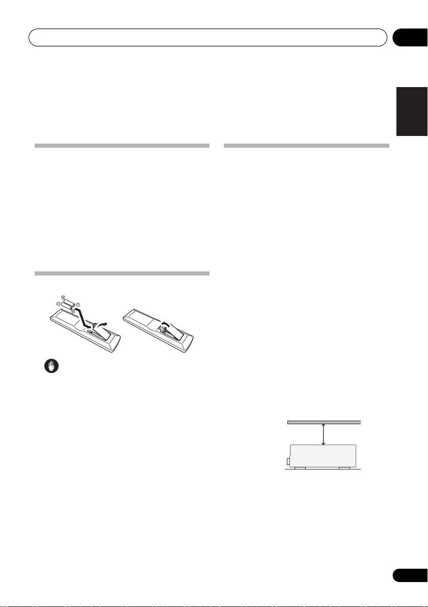
Ventilation
When installing this unit, make sure to leave
space around the unit for ventilation to
improve heat dispersal (at least 60 cm at the
Caution
top). If not enough space is provided
between the unit and walls or other
Español
Incorrect use of batteries may result in such
equipment, heat will build up inside,
hazards as leakage and bursting. Observe the
interfering with performance and/or causing
following precautions:
malfunctions.
• Never use new and old batteries together.
• Insert the plus and minus sides of the
batteries properly according to the marks
Deutsch
in the battery case.
• Batteries with the same shape may have
different voltages. Do not use different
batteries together.
•When disposing of used batteries, please
Slot and openings in the cabinet are
comply with governmental regulations or
provided for ventilation and to protect the
environmental public instruction’s rules
equipment from overheating. To prevent fire
that apply in your country or area.
hazard, do not place anything directly on top of
• Do not use or store batterie
s in direct
the unit, make sure the openings are never
sunlight or other excessively hot
place,
blocked or covered with items (such as
such as inside a car or near a heater. This
newspapers, table-cloths and curtains), and do
can cause batteries to leak, overheat,
explode or catch fire. It can also reduce the
not operate t
he equipment on thick carpet or a
life or performance of batteries.
bed.
5
En
60 cm
Receiver
VSX_519V_MY.book 5 ページ 2009年1月16日 金曜日 午後7時32分
5 minute guide02
Chapter 2:
5 minute guide
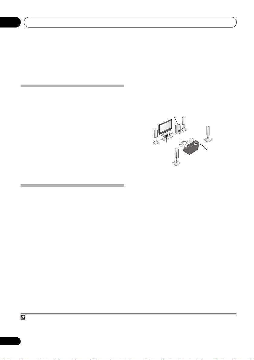
Where you place the speakers will have a big
effect on the sound. Place your speakers as
Introduction to home theater
shown below for the best surround sound
Home theater refers to the use of multiple
effect. Also see Hints on speaker placement on
audio tracks to create a surround sound effect,
page 17 for more on this.
making you feel like you’re in the middle of the
action or concert. The surround sound you get
from a home theater system depends not only
on your speaker setup, but also on the source
and the sound settings of the receiver.
This receiver will automatically decode
multichannel Dolby Digital, DTS, or Dolby
Surround sources according to your speaker
setup. In most cases, you won’t have to make
changes for realistic surround sound, but
other possibilities (like listening to a CD with
3 Plug in and switch on the receiver,
multichannel surround sound) are explained in
followed by your BD/DVD player,
Listening to your system on page 26.
subwoofer and TV.
Make sure you’ve set the video input on your TV
Listening to Surround Sound
to this receiver. Check the manual that came
with the TV if you don’t know how to do this.
With the following quick setup guide, you should
have your system hooked up for surround sound
4 Set the connection of the speaker and the
in no time at all. In most cases, you can simply
subwoofer.
leave the receiver in the default settings.
Perform Speaker setting of Manual speaker
•Be sure to complete all connections before
setup in Using the System Setup menu on
connecting to an AC power source.
page 33.
1 Connect your TV and Blu-ray Disc player
5 Play a BD/DVD, and adjust the volume.
or DVD player.
Make sure that BD/DVD is showing in the
See
Connecting a TV and Blu-ray Disc player or
receiver’s display, indicating that the BD/DVD
DVD player
on page 9 to do this. For surround
input is selected. If it isn’t, press BD on the
sound, you’ll want to hook up using a digital
remote to set the receiver to the BD/DVD input.
connection from the BD/DVD player to the receiver.
There are several other sound options you can
2 Connect your speakers and place them for
select. See Listening to your system on page 26
1
optimal surround sound.
for more on this.
See also The System Setup
See Connecting the speakers on page 16.
menu on page 33 for more setup options.
6
En
Note
VSX_519V_MY.book 6 ページ 2009年1月16日 金曜日 午後7時32分
Subwoofer (SW)
Front
Right (R)
Surround
Front
Right (SR)
Left (L)
Center (C)
Listening
position
Surround
Left (SL)
1Depending on your BD/DVD player or source discs, you may only get digital 2 channel stereo and analog sound. In this case,
the listening mode must be set to STANDARD (it should already be set—see Listening in surround sound on page 26 if you
need to do this) if you want multichannel surround sound.
Connecting up 03
Chapter 3:
English
Connecting up
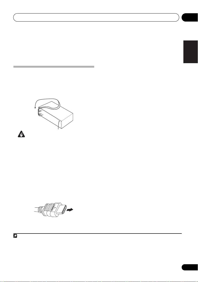
Be careful to connect the terminal in the
proper direction.
Français
Making cable connections
Make sure not to bend the cables over the top
About HDMI
of this unit (as shown in the illustration). If this
HDMI (High Definition Multimedia Interface)
happens, the magnetic field produced by the
supports both video and audio on a single
transformers in this unit may cause a
digital connection for use with DVD players,
humming noise from the speakers.
DTV, set-top boxes, and other AV devices. HDMI
was developed to provide the technologies of
High Bandwidth Digital Content Protection
(HDCP) as well as Digital Visual Interface (DVI)
in one specification. HDCP is used to protect
digital content transmitted and received by
DVI-compliant displays.
Italiano
HDMI has the capability to support standard,
enhanced, or high-definition video plus
Important
standard to multi-channel surround-sound
•Before making or changing any connections,
audio. HDMI features include uncompressed
switch off the power and disconnect the
digital video, a bandwidth of up to 2.2
Nederlands
power cord from the AC outlet.
gigabytes per second (with HDTV signals), one
•Before unplugging the power cord, switch
connector (instead of several cables and
the power into standby.
connectors), and communication between the
AV source and AV devices such as DTVs.
HDMI cables
This receiver is also compatible with the
The HDMI cables transfers uncompressed
DeepColor and x.v.Color feature (x.v.Color is
digital video, as well as almost every kind of
trademarks of Sony Corporation).
Español
digital audio that the connected component is
compatible with, including DVD-video, DVD-
• HDMI, the HDMI logo and High-Definition
Audio (see below for limitations), Video CD/
Multimedia Interface are trademarks or
Super VCD, CD, SACD (DSD 2 ch only) and
registered trademarks of HDMI Licensing,
192 kHz/8 ch (Max. number of channel inputs)
LLC.
1
PCM.
Deutsch
7
En
Note
VSX_519V_MY.book 7 ページ 2009年1月16日 金曜日 午後7時32分
HDMI cable
1 • Set the HDMI parameter in Setting the Audio options on page 30 to THRU (THROUGH) and set the input signal in Choosing
the input signal on page 32 to HDMI, if you want to hear HDMI audio output from your TV or flat screen TV (no sound will be
heard from this receiver).
• If the video signal does not appear on your TV or flat screen TV, try adjusting the resolution settings on your component or
display. Note that some components (such as video game units) have resolutions that may not be displayed. In this case, use
a (analog) composite connection.
• The signals input from the analog (composite and component) video inputs of this unit will not be output from the HDMI OUT.
Connecting up03
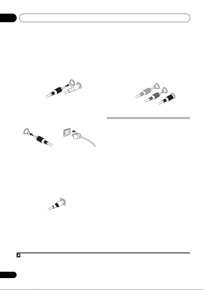
Analog audio cables
Component video cables
Use stereo RCA phono cables to connect
Use component video cables to get the best
analog audio components. These cables are
possible color reproduction of your video
typically red and white, and you should
source. The color signal of the TV is divided into
connect the red plugs to R (right) terminals
the luminance (Y) signal and the color (P
B and
and white plugs to L (left) terminals.
P
R) signals and then output. In this way,
interference between the signals is avoided.
Digital audio cables
Commercially available coaxial digital audio
cables or optical cables should be used to
1
connect digital components to this receiver.
About video outputs connection
This receiver is not loaded with a video
converter. When you use component video
cables or HDMI cables for connecting to the
input device, the same cables should be used
for connecting to the TV.
Video cables
Standard RCA video cables
These cables are the most common type of
video connection and should be used to
connect to the composite video terminals. They
have yellow plugs to distinguish them from
cables for audio.
8
En
Note
1 • When connecting optical cables, be careful when inserting the plug not to damage the shutter protecting the optical socket.
• When storing optical cable, coil loosely. The cable may be damaged if bent around sharp corners.
• You can also use a standard RCA video cable for coaxial digital connections.
Analog audio cables
Right (red)
Left (white)
Coaxial digital audio cable Optical cable
S
tandard RCA video cable
Component video cables
Green (Y)
Blue (P
B
)
Red (P
R
)
VSX_519V_MY.book 8 ページ 2009年1月16日 金曜日 午後7時32分
Connecting up 03
English
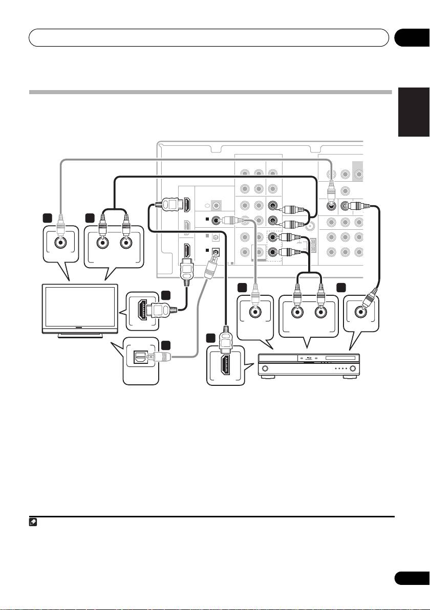
Connecting a TV and Blu-ray Disc player or DVD player
This page shows you how to connect your BD/DVD player and TV to the receiver.
Français
AUDIO
AUDIO
HDMI
IR
L
COAXIAL
ASSIGNABLE
IN 1
ANTENNA
R
(CD)
FM
UNBAL
OPTICAL
CENTERSURROUND
FRONT
75
Ω
IN 2
L
(DVR/VCR)
AM
IN 1
R
LOOP
(CD-R/TAPE)
ASSIGNABLE ASSI
BD/DVD IN
DIGITAL
1
-
2
BD/DVD MULTI CH IN
COMPONENT VIDEO
Italiano
Nederlands
Español
1 Connect the HDMI output on your BD/
2 Connect the HDMI OUT on this receiver
2
DVD player to the HDMI BD/DVD IN input on
to an HDMI input on your TV.
this receiver.
If an HDMI input is not on your TV, connect the
Use an HDMI cable for the connection. If an
MONITOR OUT video jack on this receiver to a
Deutsch
HDMI output is not on your DVD p layer, use a
video input on your TV.
digital audio cable to connect the coaxial or
1
Use a standard RCA video cable to connect to
optional output and this unit.
3
the composite video jack.
9
En
G
ZONE2 OUT
OUT
IN
MONITOR OUT BD/DVD IN TV/SA
P
R
B
YP
T
SUBW
O
PRE O
U
This receiver
OUT
CD-R/TAPE CD
IN IN
L R
L
OUT
DVR/VCR
IN
HDMI
R
BD/DVD
IN
DVR/VCR TV/SAT
TV/SAT
IN
IN
IN
L
TV/SAT
COAXIAL
MONITOR OUT BD/DVD IN
2 4
IN
IN 1
R
(CD)
L
OUT
OUT
IN 1
VIDEO IN
R
RL
(CD-R/TAPE)
SUBWOOFER
BD/DVD IN
ANALOG AUDIO OUT
1
3
2
COAXIAL
VIDEO OUT
HDMI IN
RL
DIGITAL
ANALOG AUDIO OUT
AUDIO OUT
1
TV
OPTICAL
4
DIGITAL
AUDIO OUT
HDMI OUT
BD/DVD player
Note
VSX_519V_MY.book 9 ページ 2009年1月16日 金曜日 午後7時32分
1 In this case, you’ll need to tell the receiver which digital input you connected the player to (see Choosing the input signal on
page 32).
2 When you use an HDMI cable for connection in steps 1 and 2, you can enjoy the home theater in multichannel playback without
following steps 3 and 4.
3
See
Using the component video jacks on page 14
if you want to use the component video outputs to connect this receiver to your TV.
Connecting up03
3 Connect the composite video output and
4 Connect the analog audio outputs from
1
the stereo analog audio outputs
on your BD/
your TV to the TV/SAT inputs on this receiver.
DVD player to the BD/DVD inputs on this
This will allow you to play the sound from the
receiver.
TV’s built-in tuner. Use a stereo RCA phono
2
cable to do this.
Use a standard RCA video cable
and a stereo
RCA phono cable for the connection.
•If your TV has a built-in digital decoder, you can
also connect an optical digital audio output
•If your BD/DVD player has multichannel analog
from your TV to the
DIGITAL OPTICAL IN 1
outputs, see
Connecting the multichannel
(CD-R/TAPE)
input on this receiver. Use an
analog outputs
below for how to connect it.
3
optical cable for the connection.
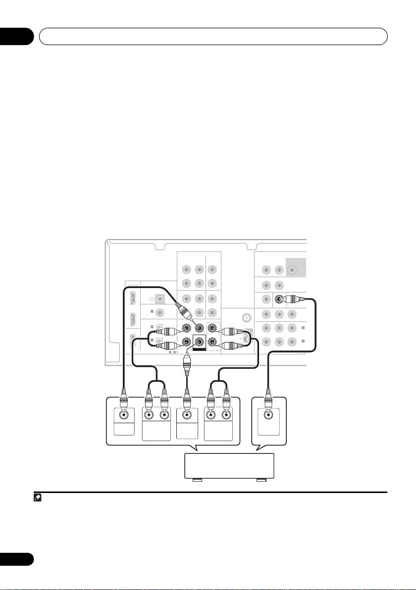
Connecting the multichannel analog outputs
For DVD Audio and SACD playback, your BD/DVD player may have 5.1 channel analog outputs. In this
case, you can connect them to the multi-channel
analog outputs to the multi-channal inputs of this
4
receiver as shown below.
10
En
Note
AUDIO
AUDIO
HDMI
L
COAXIAL
IN 1
ANTENNA
R
(CD)
FM
UNBAL
CENTERSURROUND
FRONT
75
Ω
IN 2
L
(DVR/VCR)
AM
IN 1
(CD-R/TAPE)
R
LOOP
(BD/DVD
BD/DVD IN
DIGITAL
1
-
2
BD/DVD MULTI CH IN
COMPONENT VIDEO
1
This connection will allow you to make analog recordings from your BD/DVD player.
2
If your player also has a component video output, you can connect this too. See Using the component video jacks
on page 14
.
3 In this case, you’ll need to tell the receiver which digital input you connected the TV to (see
Choosing the input signal
on page 32).
4 • The multichannel input can only be used when MULTI IN is selected (see page 32).
• You can assign COMPONENT VIDEO IN 1 or IN 2 to the multi channel input. (For more on this, see The Input Assign menu
on page 35)
)
(TV/SAT
IN 1
)
ZONE2 OUT
SUBWOOFER
L R
PRE OUT
OUT
DVR/VCR VIDE
IN
IR
OUT
DVR/VCR TV/SAT
IN
ASSIGNABLE
MONITOR OUT BD/DVD IN TV/SAT IN
P
R
B
YP
OUT
OPTICAL
IN 2
ASSIGNABLE
ASSIGNABLE
1
-
2
O
VSX_519V_MY.book 10 ページ 2009年1月16日 金曜日 午後7時32分
This receiver
OUT
CD-R/TAPE CD
IN IN
L
R
BD/DVD
IN
IN
IN
TV/SAT
BD/DVD IN
IN
CENTERSURROUND
FRONT
L
OUT
R
SUBWOOFER
SUBWOOFER
BD/DVD MULTI CH IN
CENTER
RL
SUB-
RL
VIDEO
OUTPUT
SURROUND
WOOFER
FRONT
OUTPUT
OUTPUT
OUTPUT
OUTPUT
DVD/multi-channel decoder
with multi-channel analog
output jacks
Connecting up 03
English
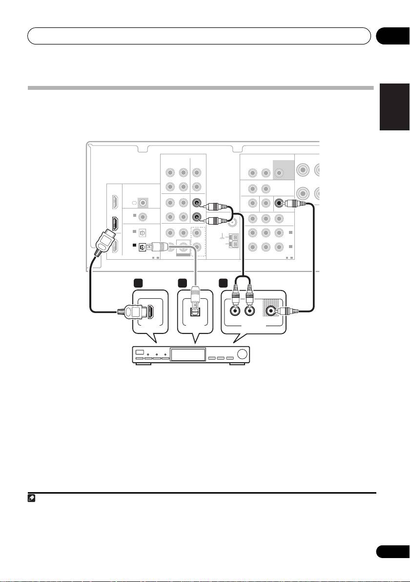
Connecting a satellite receiver or other digital set-top box
Satellite and cable receivers, and terrestrial digital TV tuners are all examples of so-called ‘set-top
boxes’.
This receiver
Français
AUDIO
AUDIO
FRONT
ZONE2 OUT
SUBWOOFER
R
OUT
CD-R/TAPE CD
IN IN
L R
PRE OUT
L
OUT
DVR/VCR VIDEO
IN
HDMI
HDMI
R
BD/DVD
IN
IR
OUT
DVR/VCR TV/SAT
IN
TV/SAT
IN
IN
IN
L
L
TV/SAT
COAXIAL
ASSIGNABLE
MONITOR OUT BD/DVD IN TV/SAT IN
TV/SAT IN
IN
IN 1
ANTENNA
P
R
B
YP
R
R
(CD)
FM
OUT
UNBAL
OPTICAL
CENTERSURROUND
FRONT
75
Ω
IN 2
L
IN 2
OUT
(DVR/VCR)
(TV/SAT)
AM
IN 1
IN 1
R
LOOP
IN 1
(CD-R/TAPE)
(CD-R/TAPE)
(BD/DVD)
ASSIGNABLE
SUBWOOFER
BD/DVD IN
ASSIGNABLE
Italiano
DIGITAL
1
-
2
BD/DVD MULTI CH IN
COMPONENT VIDEO
1
-
2
1 1 2
Nederlands
OPTICAL
VIDEOAUDIORL
HDMI OUT
DIGITAL OUT
AUDIO/VIDEO OUT
Español
STB
1 If your set-top box has an HDMI output,
2 Connect a set of audio/video outputs on
connect it to an HDMI TV/SAT IN on this
the set-top box component to the TV/SAT
2
reciever.
AUDIO and VIDEO inputs on this receiver.
If your set-top box does not have an HDMI
Use a stereo RCA phono cable for the audio
Deutsch
output but a digital output, connect it to a
connection and a standard RCA video cable
3
digital input on this receiver.
for the video connection.
The example shows an optical connection to
the DIGITAL OPTICAL IN 1 (CD-R/TAPE)
1
input.
11
En
Note
VSX_519V_MY.book 11 ページ 2009年1月16日 金曜日 午後7時32分
1 In this case, you’ll need to tell the receiver which digital input you connected the set-top box to (see Choosing the input signal
on page 32).
2 If you’ve already connected your TV to the TV/SAT inputs, simply choose another input. However, you’ll need to remember
which input you connected the set-top box to.
3 See Using the component video jacks on page 14 if your set-top box also has a component video output.
Connecting up03
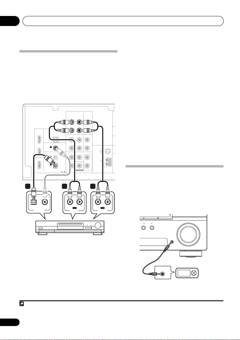
1 If your component has a digital output,
connect this to a digital input on the receiver.
Connecting other audio
The example shows an optical connection to
components
the DIGITAL OPTICAL IN 1 (CD-R/TAPE)
The number and kind of connections depends
input.
1
on the kind of component you’re connecting.
2 If necessary, connect the analog audio
Follow the steps below to connect a CD-R, MD,
outputs of the component to a set of spare
DAT, tape recorder or other audio component.
audio inputs on this receiver.
You’ll need to make this connection for
components without a digital output, or if you
want to record from a digital component. Use a
stereo RCA phono cable as shown.
3 If you’re connecting a recorder, connect
the analog audio outputs to the analog audio
inputs on the recorder.
The example shows an analog connection to
the CD-R/TAPE analog output jack using a
stereo RCA phono cable.
Connecting to the front panel
audio mini jack
Front audio connections are accessed via the
front panel using the INPUT SELECTOR or
PORTABLE button on the remote control. Use
a stereo mini-jack cable to connect a digital
audio player, etc.
12
En
Note
AUDIO
DIGITAL
1 Note that you must connect digital components to analog audio jacks if you want to record to/from digital components (like
an MD) to/from analog components.
C
HDMI
IR
OUT
IN
L
COAXIAL
ASSIGNABLE
M
IN 1
ANTENNA
R
(CD)
OPTICAL
CENTERSURROUND
FRONT
IN 2
L
(DVR/VCR)
AM
IN 1
R
LOOP
(CD-R/TAPE)
ASSIGNABLE
BD/DVD IN
1
-
2
BD/DVD MULTI CH IN
O
This receiver
AUDIO
OUT
OUT
CD-R/TAPE CD
CD-R/TAPE
IN IN
IN
L
L
R
R
BD/DVD
IN
DVR/VCR TV/SAT
IN
IN
TV/SAT
COAXIAL
IN
IN 2
(CD)
OPTICAL
OUT
IN 1
(CD-R/TAPE)
SUBWOOFER
DIGITAL
1 23
OPTICAL COAXIAL
RL
IN
RL
OUT
REC
PLAY
DIGITAL OUT
AUDIO IN
AUDIO OUT
CD-R, MD, DAT, Tape recorder, etc.
PRESET
+
ENTER
CONTROL
MULTI-ZONE
ON/OFF
MASTER
VOLUME
PORTABLE
AUDIO OUT
Digital audio player, etc.
VSX_519V_MY.book 12 ページ 2009年1月16日 金曜日 午後7時32分
Connecting up 03
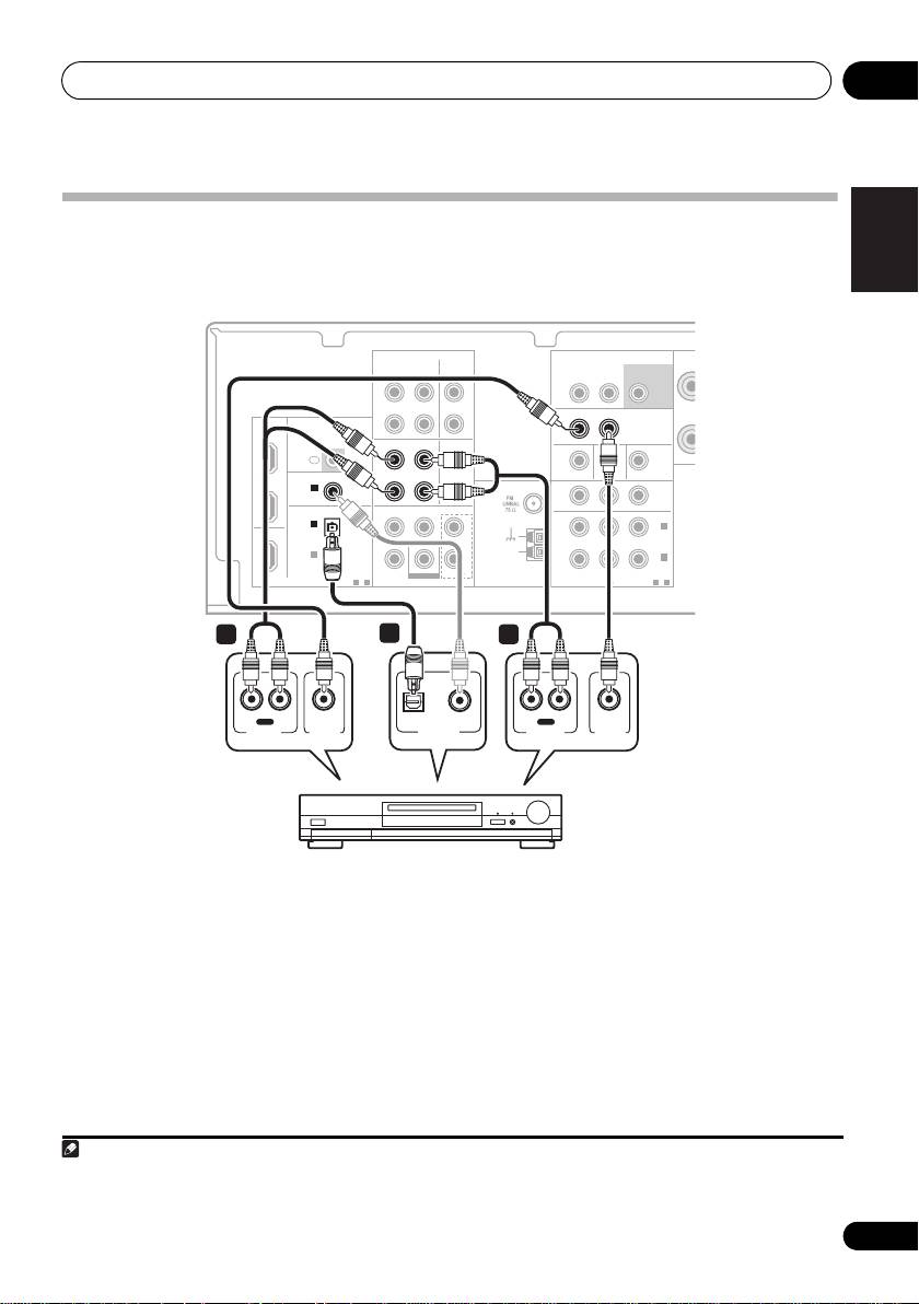
English
Connecting other video components
This receiver has audio/video inputs and outputs suitable for connecting analog or digital video
recorders, including VCRs and HDD/DVD recorders.
This receiver
Français
AUDIO
AUDIO
ZONE2 OUT
SUBWOOFER
R
OUT
CD-R/TAPE CD
IN IN
L R
PRE OUT
L
OUT
OUT
DVR/VCR VIDEO
DVR/VCR VIDEO
IN
IN
HDMI
R
BD/DVD
IN
IR
OUT
OUT
DVR/VCR TV/SAT
DVR/VCR
IN
IN
IN
IN
L
L
TV/SAT
COAXIAL
COAXIAL
ASSIGNABLE
MONITOR OUT BD/DVD IN TV/SAT IN
IN
IN 1
IN 1
ANTENNA
P
R
B
YP
R
R
(CD)
(CD)
OUT
OPTICAL
OPTICAL
CENTERSURROUND
FRONT
IN 2
IN 2
L
IN 2
OUT
(DVR/VCR)
(DVR/VCR)
(TV/SAT)
AM
IN 1
R
LOOP
IN 1
(CD-R/TAPE)
(BD/DVD)
Italiano
ASSIGNABLE
SUBWOOFER
BD/DVD IN
ASSIGNABLE
DIGITAL
DIGITAL
1
-
2
BD/DVD MULTI CH IN
COMPONENT VIDEO
1
-
2
2 1
3
Nederlands
RL
IN
REC
OPTICAL COAXIAL
RL
OUT
PLAY
AUDIO IN
VIDEO IN
DIGITAL OUT
AUDIO OUT
VIDEO OUT
Español
DVR, VCR, LD player, etc.
1 Connect a set of audio/video outputs on
2 Connect a set of audio/video inputs on
the recorder to the DVR/VCR AUDIO and
the recorder to the DVR/VCR AUDIO and
Deutsch
VIDEO inputs on this receiver.
VIDEO outputs on this receiver.
Use a stereo RCA phono cable for the audio
Use a stereo RCA phono cable for the audio
connection and a standard RCA video cable for
connection and a standard RCA video cable
the video connection.
for the video connection.
3 If your video component has a digital
audio output, connect it to a digital input on
this receiver.
The example shows a recorder connected to the
1
DIGITAL OPTICAL IN 2 (DVR/VCR)
input.
13
En
Note
VSX_519V_MY.book 13 ページ 2009年1月16日 金曜日 午後7時32分
1If your video component only has an coaxial digital output, you can connect it to the coaxial input on this receiver using an
coaxial cable. When you set up the receiver you’ll need to tell the receiver which input you connected the component to (see
Choosing the input signal on page 32).
Connecting up03
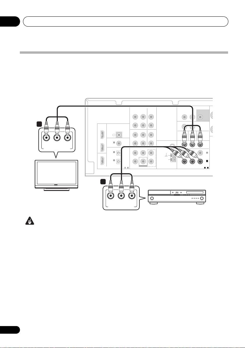
Using the component video jacks
Component video should deliver superior picture quality when compared to composite video.
Afurther advantage (if your source and TV are both compatible) is progressive-scan video, which
delivers a very stable, flicker-free picture. See the manuals that came with your TV and source
component to check whether they are progressive-scan video compatible.
AUDIO
AUDIO
ZONE2 OUT
SUBWOOFER
OUT
CD-R/TAPE CD
IN IN
L R
PRE OUT
L
OUT
DVR/VCR VIDEO
IN
HDMI
R
BD/DVD
IN
IR
OUT
DVR/VCR TV/SAT
IN
IN
IN
L
TV/SAT
COAXIAL
ASSIGNABLE
MONITOR OUT BD/DVD IN TV/SAT IN
IN
IN 1
ANTENNA
P
R
B
YP
R
(CD)
FM
OUT
UNBAL
OPTICAL
CENTERSURROUND
FRONT
75
Ω
IN 2
L
IN 2
OUT
(DVR/VCR)
(TV/SAT)
AM
IN 1
R
LOOP
IN 1
(CD-R/TAPE)
(BD/DVD)
ASSIGNABLE
SUBWOOFER
BD/DVD IN
ASSIGNABLE
DIGITAL
1
-
2
BD/DVD MULTI CH IN
COMPONENT VIDEO
1
-
2
2 If necessary, assign the component video
Important
inputs to the input source you’ve connected.
• If you connect any source component to
This only needs to be done if you didn’t connect
the receiver using a component video
according to the following defaults:
input, you must also have your TV
• COMPONENT VIDEO IN 1 – BD/DVD
connected to this receiver’s COMPONENT
• COMPONENT VIDEO IN 2 – TV/SAT
VIDEO OUT jacks.
See The Input Assign menu on page 35.
1 Connect the component video outputs of
3 Connect the COMPONENT VIDEO OUT
your source to a set of component video
jacks on this receiver to the component video
inputs on this receiver.
inputs on your TV or monitor.
Use a three-way component video cable.
Use a three-way component video cable.
14
En
This receiver
2
P
R
B
YP
P
R
B
YP
OUT
COMPONENT VIDEO IN
IN 1
(BD/DVD)
ASSIGNABLE
COMPONENT VIDEO
1
-
2
1
TV
P
R
B
YP
COMPONENT VIDEO OUT
BD/DVD player
VSX_519V_MY.book 14 ページ 2009年1月16日 金曜日 午後7時32分
Connecting up 03
Using external antennas
English
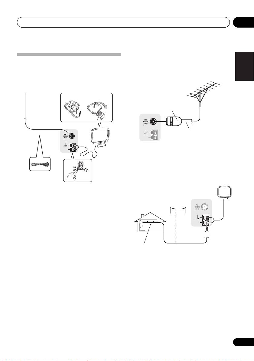
Connecting antennas
To improve FM reception
Connect the AM loop antenna and the FM wire
Use a PAL connector (not supplied) to
antenna as shown below. To improve reception
connect an external FM antenna.
and sound quality, connect external antennas
(see Using external antennas below).
Français
fig. a fig. b
2
ANTENNA
4
AM
LOOP
3
To improve AM reception
Connect a 5 m to 6 m length of vinyl-coated
Italiano
wire to the AM antenna terminal without
disconnecting the supplied AM loop antenna.
1
For the best possible reception, suspend
horizontally outdoors.
1 Push open the tabs, then insert one wire
Nederlands
fully into each terminal, then release the tabs
to secure the AM antenna wires.
2 Fix the AM loop antenna to the attached
stand.
To fix the stand to the antenna, bend in the
Español
direction indicated by the arrow (fig. a) then
clip the loop onto the stand (fig. b).
3 Place the AM antenna on a flat surface
and in a direction giving the best reception.
4 Connect the FM wire antenna in the same
way as the AM loop antenna.
Deutsch
For best results, extend the FM antenna fully
and fix to a wall or door frame. Don’t drape
loosely or leave coiled up.
15
En
One-touch
PAL connector
ANTENNA
75 Ω coaxial cable
AM
LOOP
VSX_519V_MY.book 15 ページ 2009年1月16日 金曜日 午後7時32分
Outdoor
ANTENNA
antenna
AM
LOOP
Indoor antenna
5 m to 6 m
(vinyl-coated wire)
Connecting up03
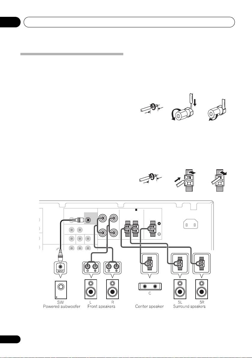
Bare wire connections
Front speaker terminals:
Connecting the speakers
A complete setup of six speakers (including the
1 Twist exposed wire strands together.
subwoofer) is shown below, but everyone’s
2 Loosen terminal and insert exposed wire.
home setup will vary.
Simply connect the
speakers you have in the manner shown below.
3 Tighten terminal.
The receiver will work with just two stereo
speakers (the front speakers in the diagram)
123
but using at least three speakers is
recommended, and a complete setup is best for
10 mm
surround sound.
If you’re not using a
subwoofer, change the front speaker setting
(see Speaker setting on page 33) to LARGE.
Center and surround speaker terminals:
Make sure you connect the speaker on the
1 Twist exposed wire strands together.
right to the right terminal and the speaker on
2 Push open the tabs and insert exposed
the left to the left terminal. Also make sure the
wire.
positive and negative (+/–) terminals on the
receiver match those on the speakers.
3 Release the tabs.
Be sure to complete all connections before
12
3
connecting this unit to the AC power source.
10 mm
AUDIO
FRONT
SPEAKERS A
ZONE2 OUT
SUBWOOFER
RL
L R
PRE OUT
SURROUND CENTER
L
MONITOR OUT BD/DVD IN TV/SAT IN
ANTENNA
P
R
B
YP
R
FM
OUT
16
En
T
VSX_519V_MY.book 16 ページ 2009年1月16日 金曜日 午後7時32分
FRONT
SPEAKERS A
SUBWOOFER
RL
IN
PRE OUT
SURROUND CENTER
AC IN
RL
RL
L
OUT
DVR/VCR VIDEO
IN
R
IN
VSX_519V_MY.book 17 ページ 2009年1月16日 金曜日 午後7時32分
Connecting up 03
•Try not to place the surround spea
kers
English
Caution
further away from the l
istening position
•These speaker terminals carry
than the front and center speakers. Doing
HAZARDOUS LIVE voltage. To prevent
so can weaken the surround sound effect.
the risk of electric shock when connecting
• To achieve the best possible surround
or disconnecting the speaker cables,
sound, install your speakers as shown
Français
disconnect the power cord before touching
below. Be sure all speakers are installed
any uninsulated parts.
securely to prevent accidents and improve
sound quality.
•Make sure that all the bare speaker wire is
twisted together and inserted fully into the
speaker terminal. If any of the bare speaker
Caution
wire touches the back panel it may cause
• If you choose to install the center speaker
the power to cut off as a safety measure.
on top of the TV, be sure to secure it with
putty, or by other suitable means, to reduce
Hints on speaker placement
the risk of damage or injury resulting from
Speakers are usually designed with a
the speaker falling from the TV in the event
particular placement in mind. Some are
of external shocks such as earthquakes.
Italiano
designed to be floorstanding, while others
•Make sure no exposed speaker wire is
should be placed on stands to sound their best.
touching the rear panel, this may cause
Some should be placed near a wall; others
the receiver to turn off automatically.
should be placed away from walls. We have
provided a few tips on getting the best sound
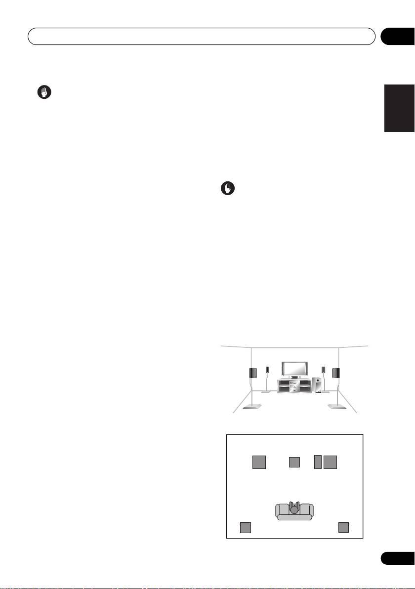
Speaker placement diagrams
Nederlands
from your speakers (following), but you should
The following illustrations show 5.1 channel
also follow the guidelines on placement that
speaker setups.
the speaker manufacturer provided with your
3-D view of
5.1 channel
speaker setup
particular speakers to get the most out of them.
•Place the front left and right speakers at
equal distances from the TV.
Español
• When placing speakers near the TV, we
recommend using magnetically shielded
speakers to prevent possible interference,
such as discoloration of the picture when
the TV is switched on. If you do not have
Deutsch
magnetically shielded speakers and notice
Overhead view of speaker setup
discoloration of the TV pictur e, move the
speakers farther away from the TV.
Front
Front
left
rightCenter
• Place the center speaker above or below
the TV so that the sound of the center
Subwoofer
channel is localized at the TV screen.
•If possible, place the surround speakers
slightly above ear level.
Surround
Surround
left
right
Listening position
17
En

Connecting up03
Connecting an IR receiver
Plugging in the receiver
If you keep your stereo components in a closed
Only plug in after you have connected all your
cabinet or shelving unit, or you wish to use the
components to this receiver, including the
sub zone remote control in another zone, you
speakers.
can use an optional IR receiver (such as a Niles
or Xantech unit) to control your system instead
Caution
of the remote sensor on the front panel of this
1
• Handle the power cord by the plug part. Do
receiver.
not pull out the plug by tugging the cord,
1 Connect the IR receiver sensor to the
and never touch the power cord when your
IR IN
jack on the rear of this receiver.
hands are wet, as this could cause a short
For more information on connecting the IR
circuit or electric shock. Do not place the
receiver, see the Installation Instructions for
unit, a piece of furniture, or other object on
the IR Receiver.
the power cord or pinch the cord in any
other way. Never make a knot in the cord or
tie it with other cables. The power cords
should b
e routed so that they are not likely
to be stepped on. A damaged power cord
can cause a fire or give you an electric
shock. Check the power cord once in a
while. If you find it damaged, ask your
nearest Pioneer authorized independent
service company for a replacement.
• Do not use any power cord other than the
one supplied with this unit.
• Do not use the supplied power cord for any
purpose other than that described below.
•The receiver should be disconnected by
removing the mains plug fr om the wall
socket when not in regular use,
e.g., when
on vacation.
1 Plug the supplied power cord into the
AC
IN
socket on the back of the receiver.
2 Plug the other end into a power outlet.
18
En
Note
VSX_519V_MY.book 18 ページ 2009年1月16日 金曜日 午後7時32分
1• Remote operation may not be possible if direct light from a strong fluorescent lamp is shining on the IR receiver remote
sensor window.
• Note that other manufacturers may not use the IR terminology. Refer to the manual that came with your component to check
for IR compatibility.
• If using two remote controls (at the same time), the IR receiver’s remote sensor takes priority over the remote sensor on the
front panel.
VSX_519V_MY.book 19 ページ 2009年1月16日 金曜日 午後7時32分
Controls and displays 04
Chapter 4:
English
Controls and displays
Français
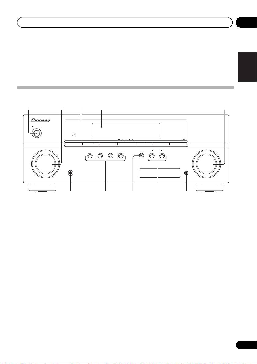
Front panel
1 23 54
AUDIO/ VIDEO MULTI-CHANNEL RECEIVER
VSX-519V
STANDBY/ON
CONTROL
PHASE
BAND
TUNE TUNE
+
TUNER EDIT ENTER
PRESET PRESET
+
INPUT
AUTO SURROUND/
STEREO/
ADVANCED
STANDARD
SPEAKERS
MULTI-ZONE
MASTER
SELECTOR
STREAM DIRECT
A.L.C.
SURROUND
SURROUND
CONTROL
ON/OFF
VOLUME
Italiano
PHONES
PORTABLE
Nederlands
6 107 98
1
STANDBY/ON
5
MASTER VOLUME
dial
2
INPUT SELECTOR
dial
6
PHONES
jack
Selects an input source.
Use to connect headphones (page 32).
Español
3 Tuner control buttons
7 Listening mode buttons
BAND
AUTO SURROUND/STREAM DIRECT
Switches between AM, FM ST (stereo) and
Switches between Auto surround mode
FM MONO radio bands (page 38).
(Auto playback on page 26) and Stream
TUNE +/–
Direct playback. Stream Direct playback
Deutsch
Used to find radio frequencies (page 38).
bypasses the tone controls for the most
accurate reproduction of a source
TUNER EDIT
(page 28).
Use with TUNE +/–, PRESET +/– and
ENTER to memorize and name stations for
STEREO/A.L.C.
recall (page 38, 39).
Switches between stereo playback, Auto
level control stereo mode (page 27) and
PRESET +/–
Front Stage Surround Advance modes
Use to select preset radio stations
(page 28).
(page 38).
4 Character display
See Display on page 21.
19
En
Controls and displays04
ADVANCED SURROUND
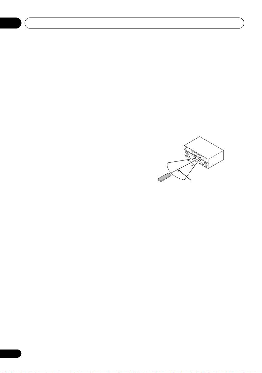
Operating range of remote control
Switches between the various surround
unit
modes (page 27).
The remote control may not work properly if:
STANDARD SURROUND
•There are obstacles between the remote
Press for Standard decoding and to switch
control and the receiver’s remote sensor.
between the various 2 Pro Logic II options
•Direct sunlight or fluorescent light is
(page 26).
shining onto the remote sensor.
8 SPEAKERS
•The receiver is located near a device that is
Use to change the speaker system on or off
emitting infrared rays.
(page 32).
•The receiver is operated simultaneously
9 MULTI ZONE controls
with another infrared remote control unit.
If you’ve made MULTI-ZONE connections (see
MULTI-ZONE listening on page 36) use these
conrols to control the sub zone from the main
zone (see Using the MULTI-ZONE controls on
page 37).
10 PORTABLE audio input jack
Connect an auxiliary component using a stereo
mini-jack cable (page 12).
20
En
STANDBY/ON
INPUT
SELECTOR
PHASE
CONTROL
BAND
AUTO SURROUND/
STREAM DIRECT
TUNE
–
PHONES
STEREO/
A.L.C.
ADVANCED
SURROUND
TUNE
+
STANDARD
SURROUND
TUNER
EDIT ENTER
SPEAKERS
PRESET
–
AUDIO
/
VIDEO MULTI-
CONTROL
PRESET
+
CHANNEL
MULTI-ZONE
RECEIVER
ON/OFF
VSX
–
519V
30
PORTABLE
MASTER
VOLUME
30
7 m
VSX_519V_MY.book 20 ページ 2009年1月16日 金曜日 午後7時32分
