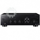
Pioneer A-70-K: instruction
Class: Video Audio Photo Equipment
Type:
Manual for Pioneer A-70-K
Table of contents

A70_SYXE8.book 1 ページ 2012年7月27日 金曜日 午後6時53分
Operating Instructions | Mode d’emploi | Bedienungsanleitung |
Istruzioni per I’uso | Handleiding | Manual de instrucciones |
Инструкции по эксплуатации
ME06
A-70-K/-S
Integrated Amplifier | Amplificateur Intégré |
Eingebauter Verstärker | Amplificatore Integrato |
Geïntegreerde versterker | Amplificador integrado |
Интегральный усилитель
A-
50-K/-S
A70_SYXE8.book 2 ページ 2012年7月27日 金曜日 午後6時53分
WARNING
IMPORTANT
This equipment is not waterproof. To prevent a fire or
shock hazard, do not place any container filled with
CAUTION
liquid near this equipment (such as a vase or flower
RISK OF ELECTRIC SHOCK
pot) or expose it to dripping, splashing, rain or
DO NOT OPEN
moisture.
D3-4-2-1-3_A1_En
The lightning flash with arrowhead symbol,
CAUTION:
The exclamation point within an equilateral
within an equilateral triangle, is intended to
TO PREVENT THE RISK OF ELECTRIC
triangle is intended to alert the user to the
alert the user to the presence of uninsulated
SHOCK, DO NOT REMOVE COVER (OR
presence of important operating and
WARNING
“dangerous voltage” within the product’s
BACK). NO USER-SERVICEABLE PARTS
maintenance (servicing) instructions in the
Before plugging in for the first time, read the following
enclosure that may be of sufficient
INSIDE. REFER SERVICING TO QUALIFIED
literature accompanying the appliance.
magnitude to constitute a risk of electric
SERVICE PERSONNEL.
section carefully.
shock to persons.
D3-4-2-1-1_A1_En
The voltage of the available power supply differs
according to country or region. Be sure that the
power supply voltage of the area where this unit
will be used meets the required voltage (e.g., 230 V
or 120 V) written on the rear panel.
Information for users on collection and disposal of old equipment and used batteries
D3-4-2-1-4*_A1_En
Symbol for
These symbols on the products, packaging, and/or accompanying documents mean
equipment
that used electrical and electronic products and batteries should not be mixed with
WARNING
general household waste.
To prevent a fire hazard, do not place any naked flame
For proper treatment, recovery and recycling of old products and used batteries,
sources (such as a lighted candle) on the equipment.
please take them to applicable collection points in accordance with your national
D3-4-2-1-7a_A1_En
legislation.
By disposing of these products and batteries correctly, you will help to save valuable
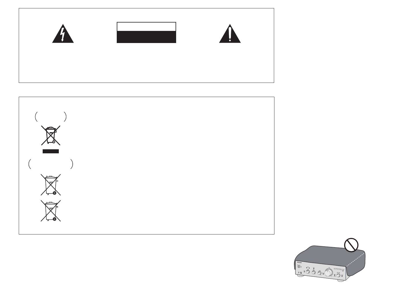
VENTILATION CAUTION
Symbol examples
resources and prevent any potential negative effects on human health and the
When installing this unit, make sure to leave space
for batteries
environment which could otherwise arise from inappropriate waste handling.
around the unit for ventilation to improve heat radiation
For more information about collection and recycling of old products and batteries,
(at least 30 cm at top, 10 cm at rear, and 10 cm at each
please contact your local municipality, your waste disposal service or the point of sale
side).
where you purchased the items.
WARNING
These symbols are only valid in the European Union.
Slots and openings in the cabinet are provided for
For countries outside the European Union:
ventilation to ensure reliable operation of the product,
and to protect it from overheating. To prevent fire
If you wish to discard these items, please contact your local authorities or dealer and
hazard, the openings should never be blocked or
ask for the correct method of disposal.
covered with items (such as newspapers, table-cloths,
Pb
K058a_A1_En
curtains) or by operating the equipment on thick carpet
or a bed.
D3-4-2-1-7b*_A1_En

A70_SYXE8.book 3 ページ 2012年7月27日 金曜日 午後6時53分
Operating Environment
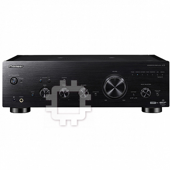
Thank you for buying this Pioneer
This product is for general household purposes. Any
Operating environment temperature and humidity:
product.
failure due to use for other than household purposes
+5 °C to +35 °C (+41 °F to +95 °F); less than 85 %RH
Please read through these operating instructions so that
(such as long-term use for business purposes in a
you will know how to operate your model properly. After
(cooling vents not blocked)
restaurant or use in a car or ship) and which requires
you have finished reading the instructions, put them in a
Do not install this unit in a poorly ventilated area, or in
repair will be charged for even during the warranty
safe place for future reference.
locations exposed to high humidity or direct sunlight (or
period.
strong artificial light)
K041_A1_En
D3-4-2-1-7c*_A1_En
Contents
If the AC plug of this unit does not match the AC
POWER-CORD CAUTION
outlet you want to use, the plug must be removed
Handle the power cord by the plug. Do not pull out the
01 Before you start
and appropriate one fitted. Replacement and
plug by tugging the cord and never touch the power
What’s in the box. . . . . . . . . . . . . . . . . . . . . . . . . .4
cord when your hands are wet as this could cause a
Loading the batteries in the remote control . . . . . .4
mounting of an AC plug on the power supply cord of
Using the remote control. . . . . . . . . . . . . . . . . . . . .4
this unit should be performed only by qualified
short circuit or electric shock. Do not place the unit, a
Installing the amplifier. . . . . . . . . . . . . . . . . . . . . .4
service personnel. If connected to an AC outlet, the
piece of furniture, etc., on the power cord, or pinch the
cut-off plug can cause severe electrical shock. Make
cord. Never make a knot in the cord or tie it with other
02 Connecting up
cords. The power cords should be routed such that they
Making cable connections. . . . . . . . . . . . . . . . . . .5
sure it is properly disposed of after removal.
The equipment should be disconnected by removing
are not likely to be stepped on. A damaged power cord
About “Bi-wiring” . . . . . . . . . . . . . . . . . . . . . . . . . . 5
can cause a fire or give you an electrical shock. Check
Connecting speaker cables . . . . . . . . . . . . . . . . . . 6
the mains plug from the wall socket when left unused
Connecting audio cables . . . . . . . . . . . . . . . . . . . .6
for a long period of time (for example, when on
the power cord once in a while. When you find it
Using centralized control with other Pioneer
vacation).
damaged, ask your nearest PIONEER authorized
components . . . . . . . . . . . . . . . . . . . . . . . . . . . . . 6
D3-4-2-2-1a_A1_En
service center or your dealer for a replacement.
Digital audio input connections (A-70 only) . . . . . .6
S002*_A1_En
Using a USB cable to connect to a computer
(A-70 only) . . . . . . . . . . . . . . . . . . . . . . . . . . . . . . . 7
CAUTION
Plugging in . . . . . . . . . . . . . . . . . . . . . . . . . . . . . .7
The /I STANDBY/ON switch on this unit will not
03 Controls and displays
completely shut off all power from the AC outlet.
Front panel . . . . . . . . . . . . . . . . . . . . . . . . . . . . . . 8
Since the power cord serves as the main disconnect
Rear panel . . . . . . . . . . . . . . . . . . . . . . . . . . . . . . . 9
device for the unit, you will need to unplug it from the
Remote control . . . . . . . . . . . . . . . . . . . . . . . . . .10
AC outlet to shut down all power. Therefore, make
04 Operation
sure the unit has been installed so that the power
Playback . . . . . . . . . . . . . . . . . . . . . . . . . . . . . . .11
cord can be easily unplugged from the AC outlet in
Set the power to Standby. . . . . . . . . . . . . . . . . . . .11
case of an accident. To avoid fire hazard, the power
When using the unit as a power amplifier . . . . . . .11
cord should also be unplugged from the AC outlet
Playing music from a digital audio component
when left unused for a long period of time (for
(A-70 only) . . . . . . . . . . . . . . . . . . . . . . . . . . . . . . .12
Playing music from a computer (A-70 only) . . . . . .12
example, when on vacation).
D3-4-2-2-2a*_A1_En
Making an audio recording . . . . . . . . . . . . . . . . .12
To set for automatic standby status
(Auto Power Down) . . . . . . . . . . . . . . . . . . . . . . . 13
Restoring all the settings to the factory default
settings . . . . . . . . . . . . . . . . . . . . . . . . . . . . . . . .13
05 Additional information
Troubleshooting. . . . . . . . . . . . . . . . . . . . . . . . . .14
Cleaning the unit . . . . . . . . . . . . . . . . . . . . . . . . . 14
Specifications . . . . . . . . . . . . . . . . . . . . . . . . . . .15
3
01 Before you start
Chapter 1:
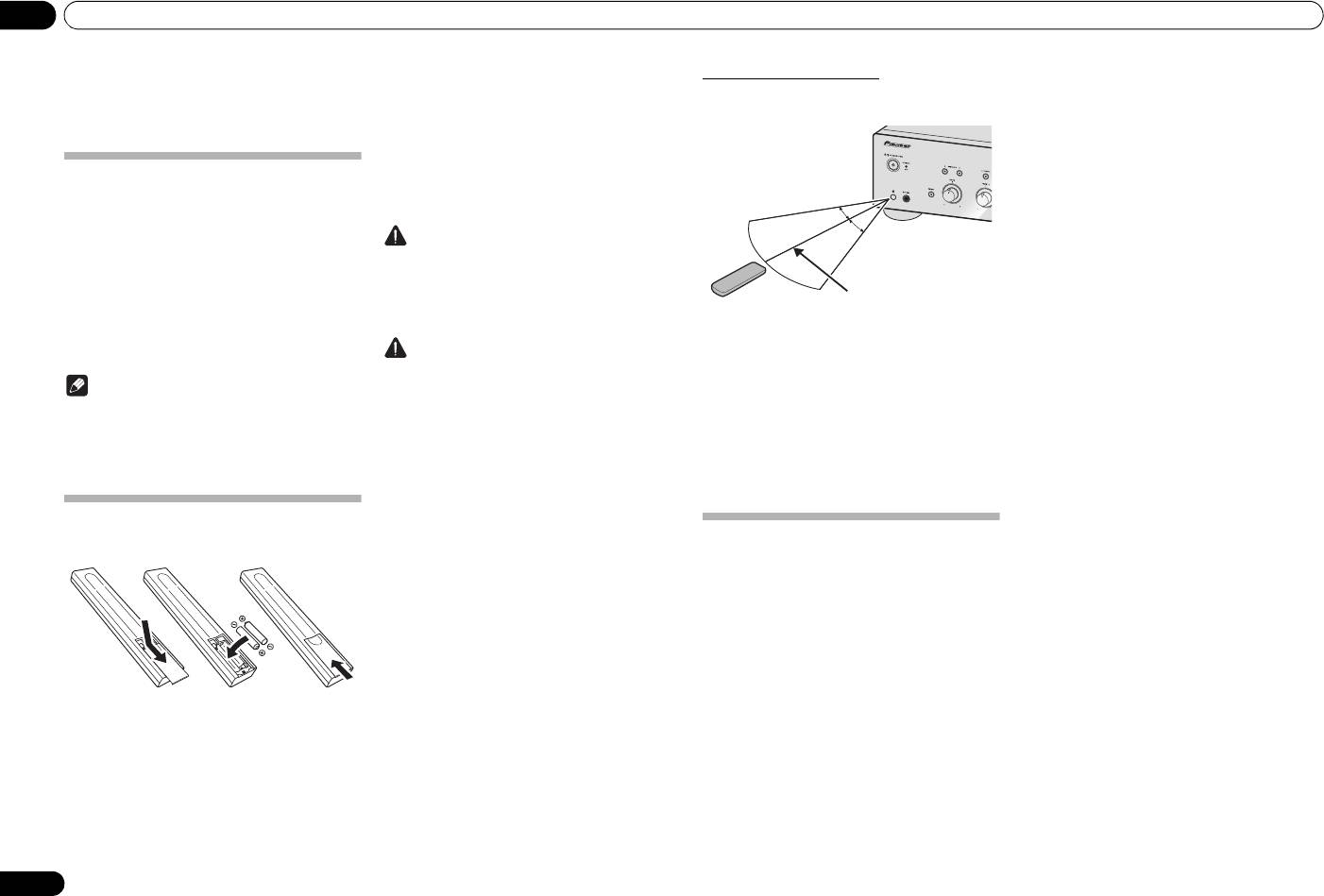
Using the remote control
The remote has a range of about 7 m at an angle of about
30º from the remote sensor.
Before you start
The batteries included with the unit have been provided
to allow you check product operation and may not last
What’s in the box
long. We recommend using alkaline batteries that have
Please confirm that the following accessories are in the
a longer life.
box when you open it.
•Remote control
WARNING
• AAA/IEC R03 dry cell batteries x2
• Short pin plug x 2
• Do not use or store batteries in direct sunlight or
(At time of purchase, these plugs have been factory
other excessively hot place, such as inside a car or
installed in the rear panel’s PHONO IN terminals.)
near a heater. This can cause batteries to leak,
• Power cord (Length: 1.8 m)
overheat, explode or catch fire. It can also reduce
• Warranty card
the life or performance of batteries.
Keep in mind the following when using the remote
• Caution sheet (To first-time users)
Caution
control:
• Operating instructions (This document)
• Make sure that there are no obstacles between the
Incorrect use of batteries may result in such hazards as
remote and the remote sensor on the unit.
Note
leakage and bursting. Observe the following
• Remote operation may become unreliable if strong
precautions:
• Illustrations featured in the Operating Instructions
sunlight or fluorescent light is shining on the unit’s
may have been modified or simplified for ease of
• When inserting the batteries, make sure not to
remote sensor.
explanation, and may therefore differ from the
damage the springs on the battery’s terminals.
• Remote controllers for different devices can
interfere with each other. Avoid using remotes for
actual product appearance.
This can cause batteries to leak or overheat.
• The illustrations used here are mainly of the A-70.
• Do not use any batteries other than the ones
other equipment located close to this unit.
specified. Also, do not use a new battery together
• Replace the batteries when you notice a fall off in
with an old one.
the operating range of the remote.
• When loading the batteries into the remote control,
Loading the batteries in the remote
set them in the proper direction, as indicated by the
polarity marks ( and ).
control
• Do not heat batteries, disassemble them, or throw
Installing the amplifier
them into flames or water.
When installing this unit, make sure to put it on a level
• Batteries may have different voltages, even if they
and stable surface.
are the same size and shape. Do not use different
• Don’t install it on the following places:
types of batteries together.
– on a color TV (the screen may distort)
1
2
• To prevent leakage of battery fluid, remove the
batteries if you do not plan to use the remote
– near a cassette deck (or close to a device that
control for a long period of time (1 month or more).
gives off a magnetic field). This may interfere with
If the fluid should leak, wipe it carefully off the
the sound.
inside of the case, then insert new batteries. If a
– in direct sunlight
battery should leak and the fluid should get on your
– in damp or wet areas
3
skin, flush it off with large quantities of water.
– in extremely hot or cold areas
• When disposing of used batteries, please comply
– in places where there is vibration or other
with governmental regulations or environmental
1 Open the rear lid.
movement
public institution’s rules that apply in your country/
– in places that are very dusty
area.
2 Insert the new batteries, matching the
– in places that have hot fumes or oils (such as a
kitchen)
polarities as indicated inside the case.
• Do not mount the unit on a sofa or other object or
3 Close the rear lid.
material with absorbent qualities, since sound
quality may be adversely affected.
4
En
30 °
30 °
7 m
A70_SYXE8.book 4 ページ 2012年7月27日 金曜日 午後6時53分
Connecting up 02
English
Chapter 2:
Connecting up
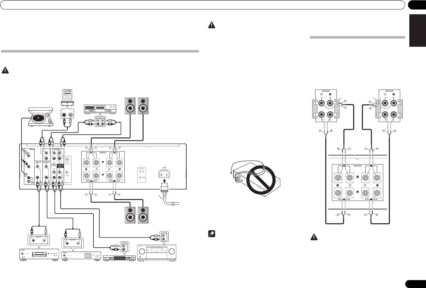
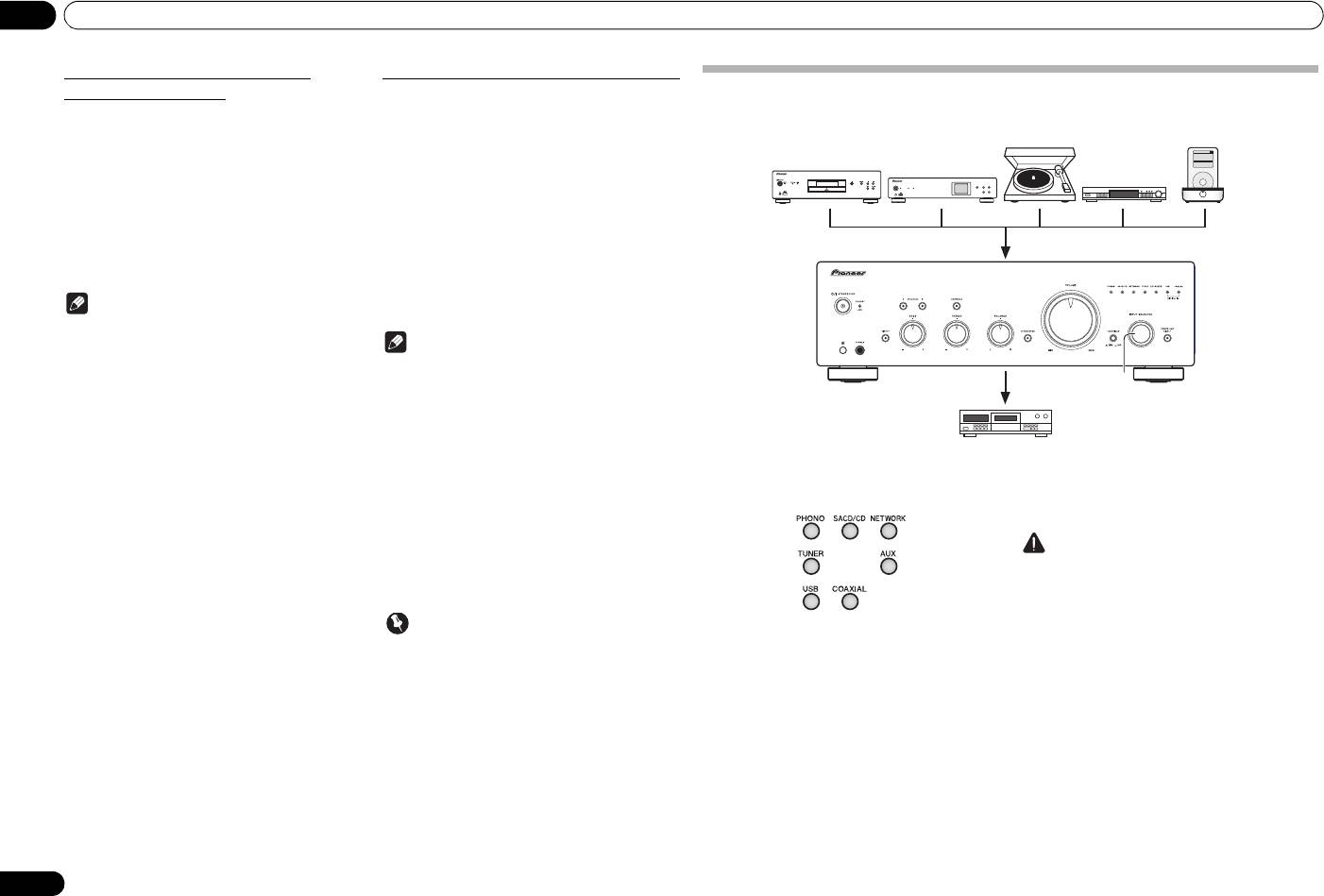
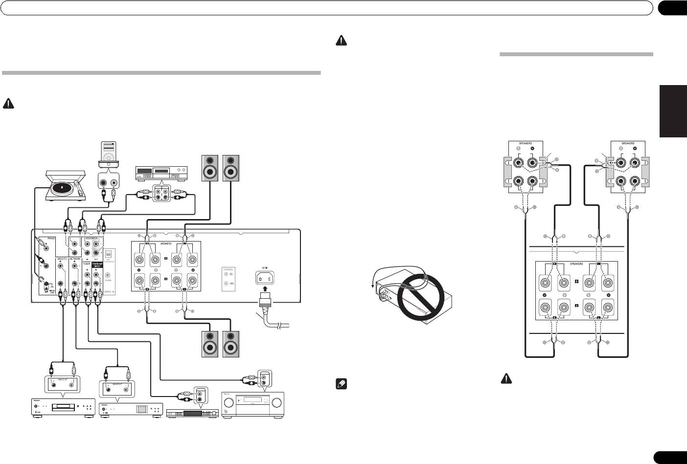
Making cable connections
Caution
• Before making or changing the connections, switch off the power and disconnect the power cord from the AC outlet.
• Connect the power cord after all the connections between devices have been completed.
DeutschFrançais
RL
OUTPUT
AUDIO
PLAY
REC
L
R
Italiano Español Русский
AUX IN
Nederlands
PRE OUT
L
R
OUTPUT
L
L
R
R
5
En
R
L
R
L
R
L
R
L
L
R
L
L
R
R
L
R
L
R
R
L
R
L
R
L
R
L
L
R
R
L
L
R
R
L
R
L
L
R
R
L
Settings>
Music>
Backlight
Shuffle Songs
Extras>
iPod
MENU
R
L
R
L
R
L
ADVANCED
MCACC
FL OFF
iPod iPhone iPadHDMI
INPUT
SELECTOR
STANDBY/ON
MASTER
VOLUME
iPod dock, etc
Speaker system B
(AUX IN terminals are
Right Left
furnished on the A-50 only)
CD recorder or
tape deck
Turntable
This unit’s
rear panel
Power cord
(included)
Right
Left
Speaker system A
SACD/CD player
Network audio player
Tuner
PRE OUT jacks on pre-
amplifier or AV amplifier
• iPod is a trademark of Apple Inc., registered in the
Caution
U.S. and other countries.
•The SIGNAL GND terminal is provided to reduce
noise when connecting the unit to components
such as an analog turntable.
About “Bi-wiring”
•The PHONO IN terminals are factory equipped with
short pin plugs. These should not be removed
This unit can be used with speakers that support bi-
except when connecting a turntable. Be sure to
wiring. Be sure to connect the high-frequency and
save the short pin plugs in a safe place.
low-frequency connections correctly.
• Do not insert the short pin plugs in any connectors
• During playback, be sure that both the SPEAKERS
other than the PHONO IN terminals. Connecting
A button and SPEAKERS B button are set to ON
them to any other terminals may cause
(page 8).
malfunctions.
• Do not connect the PHONO IN terminals to any
component other than a turntable; also, do not
connect to a turntable equipped with built-in
equalizer. An excessively high sound output may be
produced, resulting in damage to your speakers or
other devices.
• The A-50’s PHONO IN terminals are designed to be
used only with turntables equipped with MM
(moving-magnet) type cartridges. Turntables
equipped with MC (moving-coil) cartridges cannot
be used.
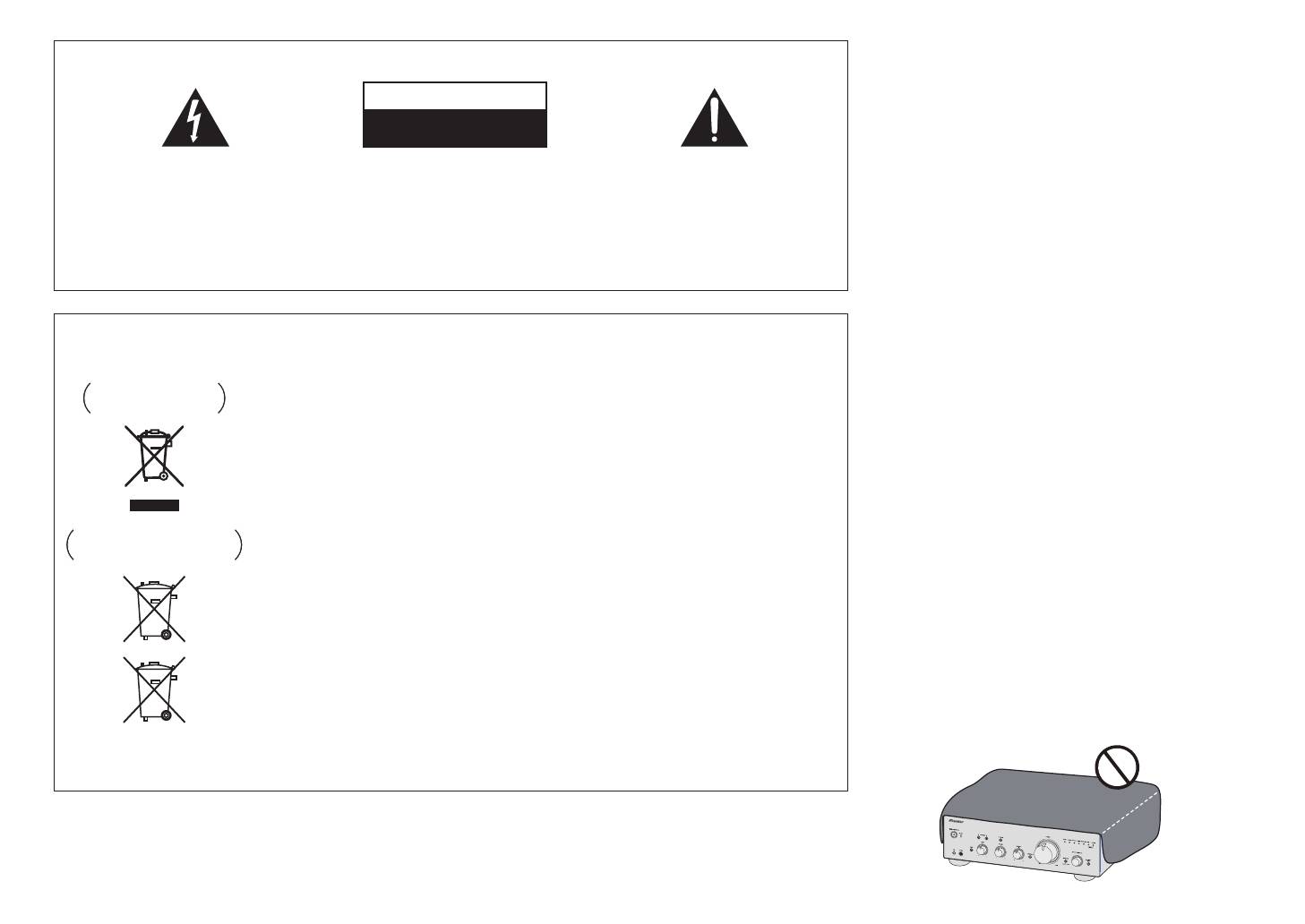
• Make sure not to bend the cables over the top of
this unit (as shown in the illustration). If this
happens, the magnetic field produced by the
transformers in this unit may cause a humming
noise from the speakers.
• The unit’s POWER AMP DIRECT terminals should
never be connected to any other component’s
connectors except PRE-AMP OUT.
• If your turntable has a grounding wire, secure it to
the ground terminal on this amplifier.
Note
Caution
• When connecting a tape cassette deck, playback
noise may be heard, depending on the installation
• When using bi-wiring to connect speakers, avoid
location. This noise is caused by leakage flux from
adverse affects on the amplifier by being sure to
the amplifier’s transformer. In this event, change
remove the HIGH and LOW short bars provided
the installation location, or move the deck farther
with the speakers. For detailed information, consult
from the amplifier.
the instructions provided with the speakers.
HIGH
HIGH
LOW
LOW
Speaker system
Speaker system
Right
Remove the shorting
Left
bar between the +
and – terminals.
This unit’s
rear panel
A70_SYXE8.book 5 ページ 2012年7月27日 金曜日 午後6時53分
02 Connecting up
• When using speakers with removable network
circuits, note that if the network is removed, no
Connecting audio cables
effect will be produced and damage may be caused
to the speaker.
Connect the white plug to the left (L) jack, and the red
• Another method of connection is to connect the
plug to the right (R) jack. Be sure to insert the plugs fully
SPEAKERS A terminals to HIGH and the SPEAKERS
into the jacks.
B terminals to LOW (reverse that shown in the
illustration).
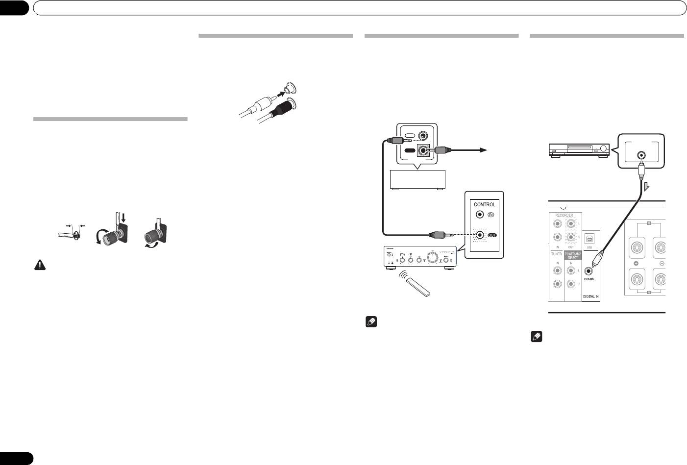
Connecting speaker cables
1 Twist the cable cores.
2 Loosen the nut on the
SPEAKERS
terminal, and insert the speaker cable into
the exposed hole in the terminal shaft.
3 Retighten the terminal nut.
123
Caution
• When using only one set of speaker terminals
(SPEAKERS A or SPEAKERS B), or when utilizing
bi-wiring connections, the speaker used should
have a nominal impedance between 4 Ω and
16 Ω. When using both sets of terminals, the
connected speakers should have nominal
impedance between 8 Ω and 32 Ω. Consult the
instructions accompanying your speakers for
details regarding the impedance value.
• Make sure the positive and negative (+/–) terminals
on the amplifier match those on the speakers.
• These speaker terminals carry HAZARDOUS live
voltage. To prevent the risk of electric shock when
connecting or disconnecting the speaker cables,
disconnect the power cord before touching any
uninsulated parts.
• Make sure that all the bare speaker wire is twisted
together and inserted fully into the speaker
terminal. If any of the bare speaker wire touches the
back panel it may cause the power to cut off as a
safety measure.
6
En
10 mm
Left (white)
Right (red)
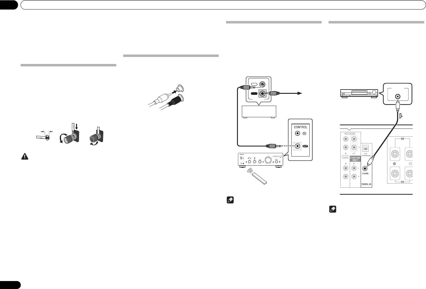
Using centralized control with other
Digital audio input connections (A-70
Pioneer components
only)
Multiple Pioneer components equipped with CONTROL
If a coaxial digital cable (sold separately) is used to
IN/OUT jacks can be connected to the unit, allowing
connect this unit’s DIGITAL IN COAXIAL terminal to the
centralized control of the components via the remote
digital audio output connector of a digital audio playback
sensor on the unit. This also allows remote control of
component, the playback component can be used to
components not equipped with a remote sensor, or
play music through this unit.
installed in places where the component’s remote
For more information regarding the output of audio
sensor cannot be accessed.
signals input to the DIGITAL IN COAXIAL terminal,
consult page 12.
IN
OUT
CONTROL
Note
• For connections use a commercially available
Note
monaural miniplug cord (without resistor).
• When connecting the CONTROL IN/OUT jacks,
• Digital signal formats that can be input to this unit
commercially available audio cords must also be
include linear PCM signals with sampling rate and
used to make analog connections. Merely
quantitative bits up to 192 kHz/32 bits. (Depending
connecting the CONTROL IN/OUT jacks alone will
on the connected device and environment,
not allow proper system control.
operation may not be successful).
• When a control cord is connected to the unit’s
CONTROL IN jack, the unit cannot be controlled by
pointing the remote control at the unit (the remote
sensor is automatically disabled).
To other Pioneer
component
equipped with
CONTROL IN jack
Other Pioneer
component equipped
with CONTROL IN/
OUT jacks
A-70
Remote
Aim remote control
control
at the sensor on the
unit.
DIGITAL OUT
COAXIAL
Digital audio
equipment, etc.
Coaxial digital audio cable
(sold separately)
A-70’s rear panel
A70_SYXE8.book 6 ページ 2012年7月27日 金曜日 午後6時53分
Connecting up 02
English
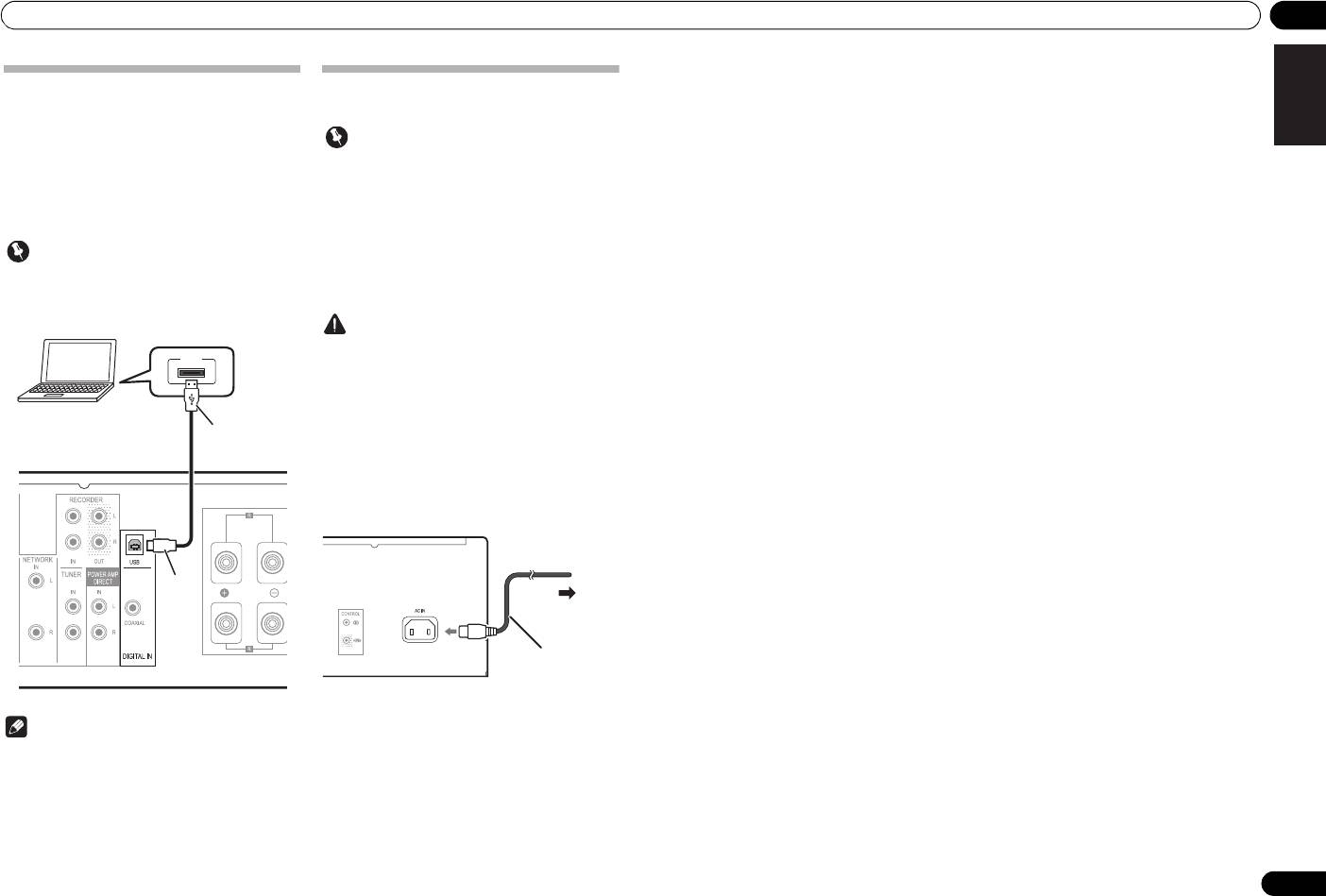
Using a USB cable to connect to a
Plugging in
computer (A-70 only)
If a USB cable (sold separately) is used to connect this
unit’s DIGITAL IN USB terminal to a computer’s USB
Important
port, music files located on the computer can be played
• When going on a trip or otherwise not using the
through this unit.
unit for an extended period, always disconnect the
For more information regarding the output of audio
power cord from its outlet. Note that various
signals input to the DIGITAL IN USB terminal, consult
internal settings will not be lost even if the power
page 12.
cord is disconnected from its outlet for an extended
time.
Important
• If it is necessary to detach the power cord, first be
sure to press the
/I
STANDBY/ON button on the
• When using this connection to input audio files
front panel of the unit so the unit is turned OFF
from a computer to this unit, it may be necessary to
before detaching the cord.
DeutschFrançais
install a special driver on the computer. For details,
see the website of Pioneer.
Caution
• The use of a power cord other than the one provided
USB
will invalidate the warranty, since Pioneer will not
be responsible for any damage incurred. (The
power cord provided with the unit has a rated
current capacity of 10 A.)
Italiano Español Русский
• Do not use any power cord other than the one
supplied with this unit.
• Do not use the supplied power cord for any purpose
other than that described below.
After you’ve finished making all connections, plug the
unit into an AC outlet.
Nederlands
1 Plug the supplied power cord into the
Note
AC IN
socket on the rear panel of the unit.
• This unit cannot be used to play audio files from a
2 Plug the other end into an AC outlet.
computer unless Media Player is installed on the
connected computer.
7
En
PC
A-type
USB cable
(sold separately)
B-type
A-70’s rear panel
This unit’s rear panel
To AC outlet
Power cord
(included)
A70_SYXE8.book 7 ページ 2012年7月27日 金曜日 午後6時53分
A70_SYXE8.book 8 ページ 2012年7月27日 金曜日 午後6時53分
03 Controls and displays
Chapter 3:
6 Remote sensor
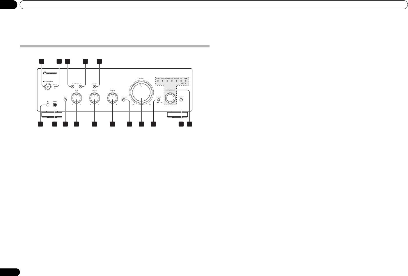
14
CARTRIDGE
select switch (A-70 only)
Receives the signals from the remote control (page 4).
Select the type of cartridge used with your turntable.
Controls and displays
7
PHONES
jack
15
POWER AMP DIRECT
button/indicator
Use to connect headphones. No sound is produced
Press this button when the unit is to be used as a power
when the POWER AMP DIRECT button is ON.
amplifier (page 11).
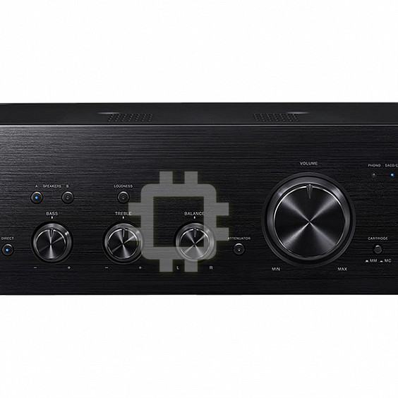
Front panel
8 DIRECT button/indicator
16
INPUT SELECTOR
knob/indicators
On : The indicator lights: When this button is set to ON,
Turn the knob clockwise or counterclockwise so that the
2 54
31
sound signals are output directly, without being passed
indicator lights for your desired input source. Turning
A-70
through the various adjustment circuits (BASS, TREBLE,
the knob clockwise causes the lit indicator to right.
BALANCE, LOUDNESS). This allows reproduction of the
Turning counterclockwise causes it to left. When the
signals with greater fidelity, but it disables any settings
remote control’s MUTE button is pressed to mute the
made with the BASS, TREBLE, BALANCE or LOUDNESS
sound, the indicator for the input source selected with
controls.
the INPUT SELECTOR knob flashes.
Off : The indicator goes off: The signal passes through
the various frequency adjusting circuits. When the
indicator is OFF, adjustments can be made with the
BASS, TREBLE, BALANCE, and LOUDNESS controls.
9
BASS
tone control
Use to adjust the low-frequency tone. The center position
is the flat (normal) position. When turned to the right,
6
7
8
9
10 11 13 15
14 1612
low-frequency tones are emphasized; when turned to the
left, low-frequency tones are de-emphasized.
1
/I
STANDBY/ON
4
SPEAKERS B
button/indicator
• This button does not operate when the DIRECT
Switches the amplifier between off and on.
Use this button to listen to the speaker system
button is in the on position.
When power is turned on, the power indicator in the
connected to SPEAKERS B terminals.
10
TREBLE
tone control
center of the button will light.
On : The indicator lights. Sound is heard from the
Use to adjust the high-frequency tone. The center
speaker system. (Sound will also be produced from the
position is the flat (normal) position. When turned to the
2
STANDBY/APD
indicator
PHONES jack.)
right, high-frequency tones are emphasized; when
When power is set to standby, the indicator lights red.
Off : The indicator goes off. No sound is heard from the
turned to the left, high-frequency tones are de-
When the Auto Power Down (APD) function is on, the
speaker system. Set to this position when listening with
emphasized.
indicator lights green (page 13).
headphones.
• This button does not operate when the DIRECT
3
SPEAKERS A
button/indicator
button is in the on position.
5
LOUDNESS
button/indicator
Use this button to listen to the speaker system
Use when listening at low volume levels.
connected to SPEAKERS A terminals.
11
BALANCE
control
On : The indicator lights: Boosts low and high
Should normally be left in the center position. Adjust
On : The indicator lights. Sound is heard from the
frequencies to give added punch to playback even at a
balance if the sound is louder from one of the speakers.
speaker system. (Sound will also be produced from the
low volume level.
If the right side is louder, turn toward the L (left) position
PHONES jack.)
Off : The indicator goes off: Should normally be left in
and if the left side is louder, turn toward the R (right)
Off : The indicator goes off. No sound is heard from the
this position.
position.
speaker system. Set to this position when listening with
• This button does not operate when the DIRECT
• This button does not operate when the DIRECT
headphones.
button is in the on position.
button is in the on position.
• When sound volume is raised, the amount of
12
ATTENUATOR
button (A-70 only)
change produced by the LOUDNESS circuit is
Press when you wish to make fine adjustments to the
reduced.
sound volume when playing at very low sound volume
levels.
13 VOLUME control
Use to adjust the volume level. (Also allows adjustment
of the headphone sound volume.)
8
En
Controls and displays 03
English
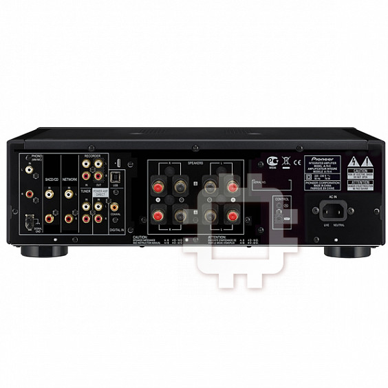
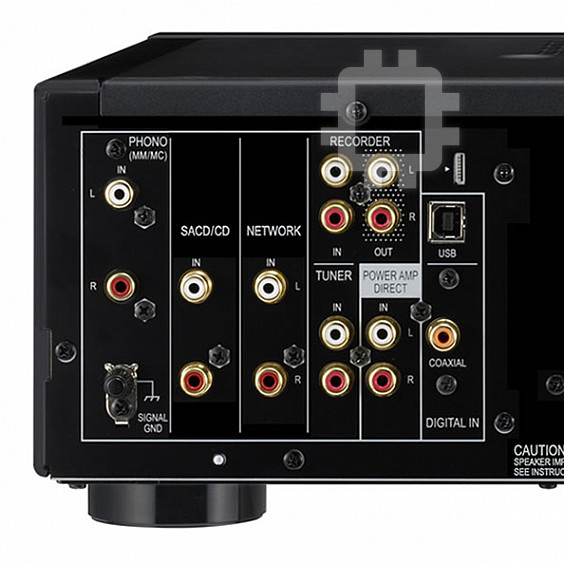
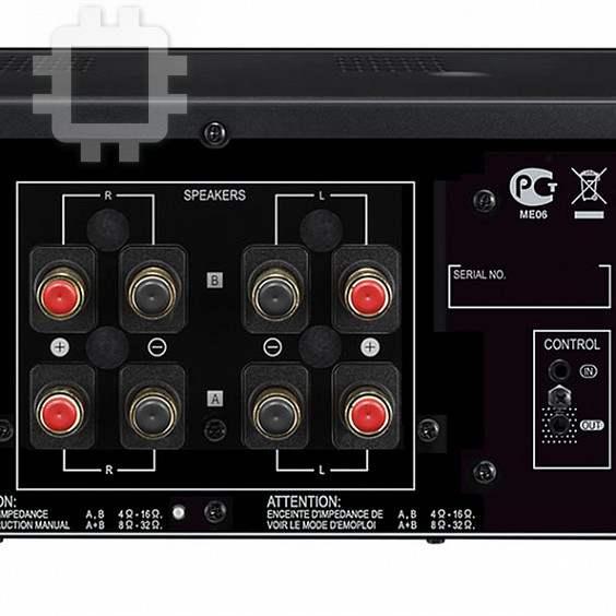
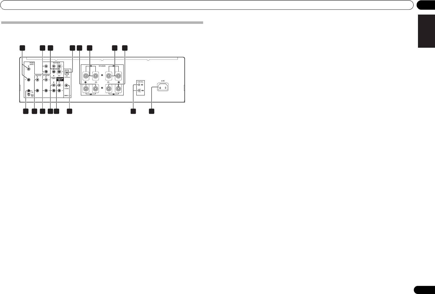
Rear panel
See pages 5-7 for details regarding connections.
DeutschFrançais
1
PHONO IN (MM/MC)
terminals (A-70)
9 GND (Turntable ground) terminal
PHONO IN (MM) terminals (A-50)
This ground terminal is designed to help reduce noise
when a turntable is connected. It is not a safety ground.
Italiano Español Русский
2
AUX
IN
terminals (A-50 only)
10
SACD/CD
IN
terminals
3
RECORDER IN/OUT
terminals
11
NETWORK
IN
terminals
4
DIGITAL IN USB
terminal (A-70 only)
12
TUNER
IN
terminals
5
SPEAKERS A
terminals (Right channel)
13
POWER AMP DIRECT
IN
terminals
6
SPEAKERS B
terminals (Right channel)
When using the unit as a power amplifier, connect the
Nederlands
pre-amplifier here (page 11).
7
SPEAKERS B
terminals (Left channel)
14
DIGITAL IN COAXIAL
terminal (A-70
8
SPEAKERS A
terminals (Left channel)
only)
15
CONTROL IN/OUT
jack
16
AC IN
jack
Connect power cord to here and an AC wall socket.
9
En
52221 2623 27 2824
AUX IN
29
10 11 12 13 1514 16
2
A70_SYXE8.book 9 ページ 2012年7月27日 金曜日 午後6時53分
A70_SYXE8.book 10 ページ 2012年7月27日 金曜日 午後6時53分
03 Controls and displays
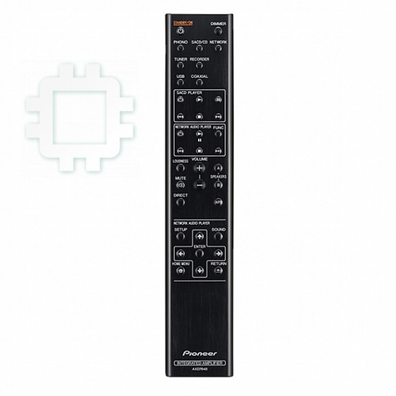
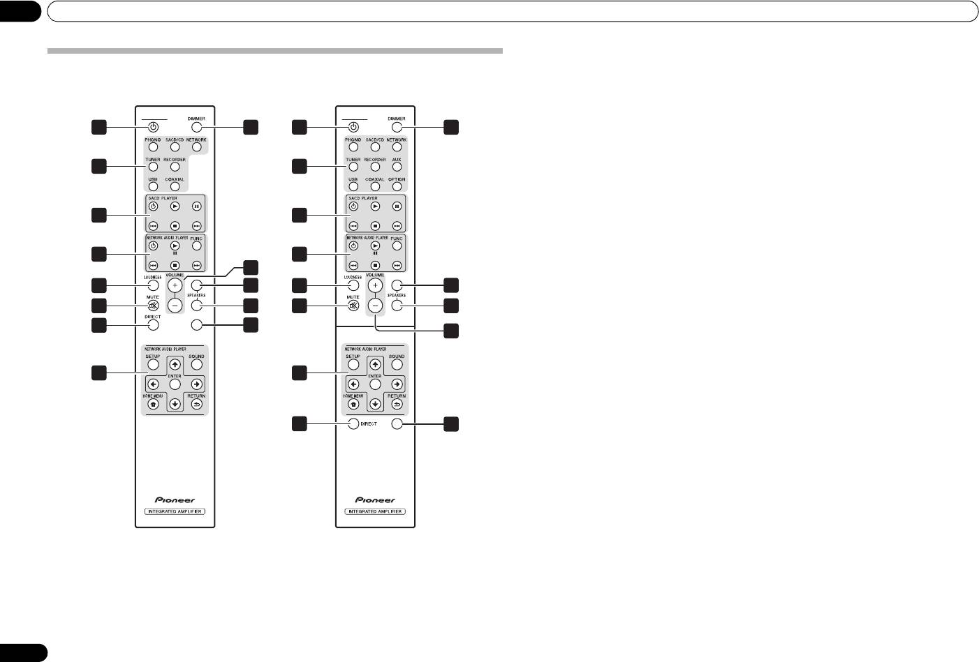
1
STANDBY/ON
Remote control
Switches the amplifier between standby and on.
2 Input selector buttons
A-70
A-50
Press to select an input source. These select the
component connected to the corresponding input on the
STANDBY/ON
STANDBY/ON
rear panel.
1
8
1
8
• When the A-50 is connected, the USB, COAXIAL,
and OPTION buttons are disabled.
3 SACD PLAYER control buttons
2
2
Use to control Pioneer SACD player.
4 NETWORK AUDIO PLAYER control
buttons
3
3
Use to control Pioneer network audio player.
5
LOUDNESS
Use to set the loudness circuit ON/OFF (page 8).
4
4
6
MUTE
9
Mutes/unmutes the sound.
5
A
10
5
A
10
7
DIRECT
6
B
11
6
B
Press to access Direct listening (page 8).
11
8
7
APD
DIMMER
12
9
This button allows the illumination of the unit's front
panel indicators to be set in three levels (does not affect
the STANDBY indicator).
4
4
9
VOLUME +/–
Use to set the listening volume.
10
SPEAKERS A
button/indicator
Use this button to listen to the speaker system
7
APD
12
connected to SPEAKERS A terminals.
11
SPEAKERS B
button/indicator
Use this button to listen to the speaker system
connected to SPEAKERS B terminals.
12
APD
Use to set the Auto Power Down function to ON/OFF
(page 13).
10
En
Operation 04
English
Chapter 4:
Operation
Playback
DeutschFrançais
Italiano Español Русский
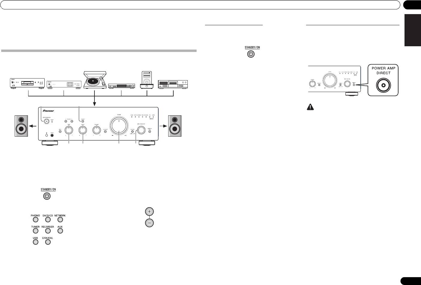
1 Turn on the power of the playback
• In the case of the A-70, if PHONO is selected, use
the CARTRIDGE select switch to designate the type
component.
of cartridge used with your turntable, either MM
Nederlands
() or MC ().
2 Turn power ON to the unit.
• If the unit is in the standby mode, press the remote
4 Start playback of the component you
control’s STANDBY/ON button.
selected in step 1.
5 Adjust playback volume with
VOLUME
control.
3 Select the source you want to playback.
6 Adjust the tone to your preference using
the
BASS
and
TREBLE
controls, and
LOUDNESS
button.
Select the playback component.
If the DIRECT button has been set to ON, these controls
are disabled.
• When using the front panel controls, rotate the
INPUT SELECTOR knob.
11
En
Music>
Extras>
iPod
Settings>
Shuffle Songs
Backlight
MENU
/I STANDBY/ON
FUNCTION
NETWORK AUDIO PLAYER
N-50
iPod/USB
5V 2.1A
STANDBY
PURE AUDIO Hi-Bit 32
62
3566
Turntable
iPod dock, etc
SACD/CD player
CD recorder or
Network audio player
tape deck
Tuner
Playback
Playback
A70_SYXE8.book 11 ページ 2012年7月27日 金曜日 午後6時53分
Set the power to Standby
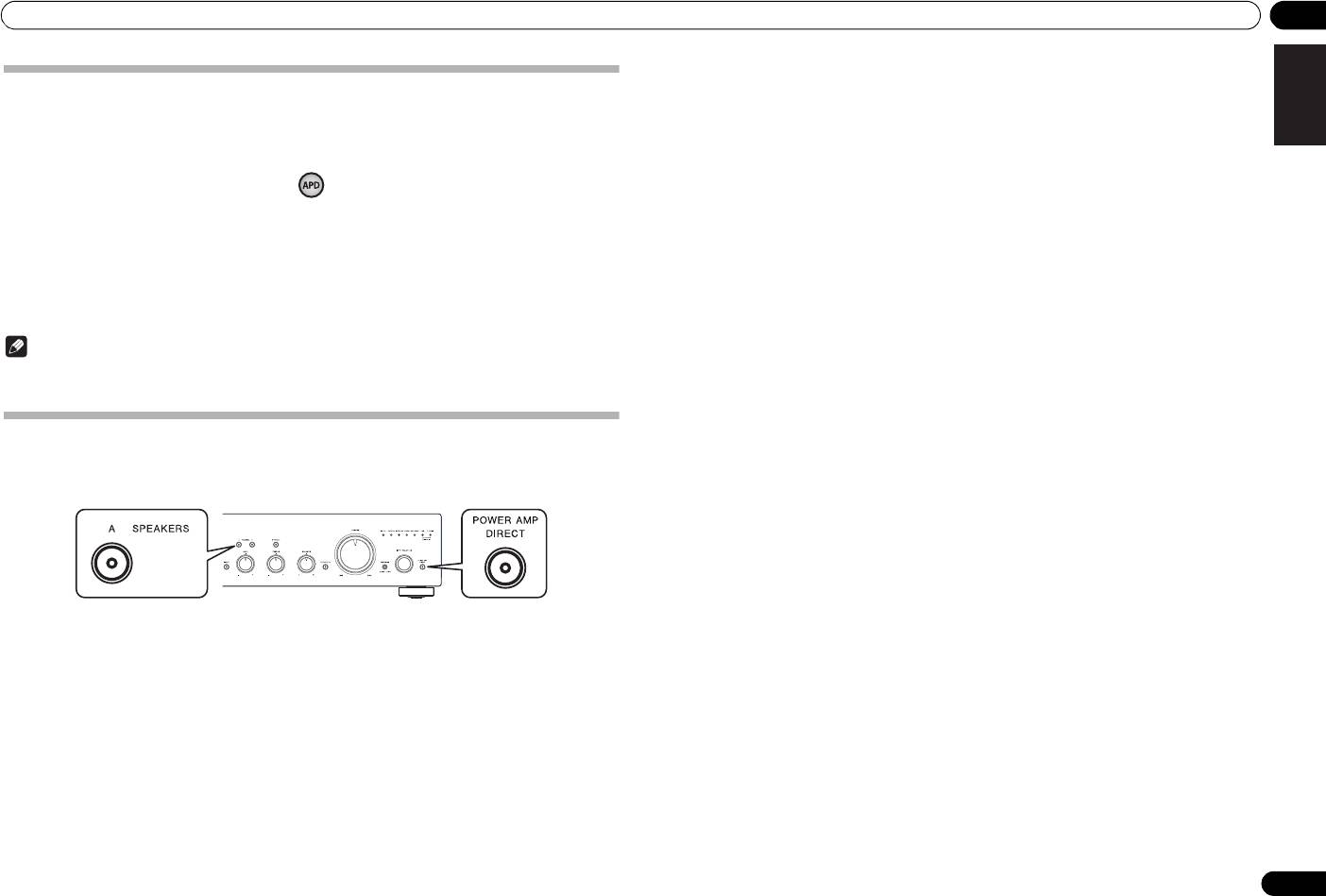
When using the unit as a power amplifier
When a pre-amplifier is connected to the unit’s POWER
1 Press the remote control’s
STANDBY/
AMP DIRECT IN terminals, the unit can be used as a
ON
button.
power amplifier.
1 Press the
POWER AMP DIRECT
button
on the front panel of the unit.
The POWER AMP DIRECT indicator will light.
The next time you wish to turn on the power, press the
remote control’s STANDBY/ON button.
• If the front panel’s /I STANDBY/ON button is
pressed, the power will be turned off. In this case, if
the power is off, pressing the remote control’s
STANDBY/ON button will not turn on the power.
To turn on the power again, press the front panel’s
/I STANDBY/ON button.
Caution
• When the POWER AMP DIRECT indicator is
lighted, operations change as follows:
– The unit’s front-panel VOLUME, BASS, TREBLE,
and BALANCE controls are disabled. These
adjustments are controlled by the component
connected to the unit’s POWER AMP DIRECT IN
terminals.
–The LOUDNESS button and ATTENUATOR
button (A-70 only) are disabled.
– When the POWER AMP DIRECT indicator is
lighted, sound volume from the unit will
automatically be fixed at its maximum output.
When using this unit as a power amplifier,
check the output level of the component
connected to the POWER AMP DIRECT IN
terminals and set it to a low level as appropriate
before turning on the POWER AMP DIRECT
indicator. If the sound volume of the component
connected to the POWER AMP DIRECT IN
terminals is initially set to a high output level,
VOLUME
loud sound may suddenly be output when the
POWER AMP DIRECT indicator lights.
– Sound is not produced from the PHONES jack
and RECORDER OUT terminals.
• For more information, consult the operating
instructions for the component connected to the
unit’s POWER AMP DIRECT IN terminals.
04 Operation
Playing music from a digital audio
Playing music from a computer (A-70 only)
component (A-70 only)
Use this function to play digital audio input to the unit's
Making an audio recording
rear panel DIGITAL IN USB port.
Outputs digital signals input to the DIGITAL IN
You can make an audio recording from any audio source connected to the amplifier.
COAXIAL connectors.
1 Connect the unit to a computer via USB
1 Make a digital input connection.
cable
Extras>
Music>
iPod
Settings>
Backlight
Shuffle Songs
• See Digital audio input connections on page 6.
• See Using a USB cable to connect to a computer on
MENU
page 7.
/I STANDBY/ON
FUNCTION
NETWORK AUDIO PLAYER
N-50
STANDBY
PURE AUDIO Hi-Bit 32
2 Press
COAXIAL
to select
DIGITAL IN
iPod/USB
5V 2.1A
COAXIAL
as the input source.
2 Press
USB
to select
DIGITAL IN USB
as
• When using the front panel controls, rotate the
the input source.
INPUT SELECTOR knob.
• When using the front panel controls, rotate the
• Sound is produced from the RECORDER OUT
INPUT SELECTOR knob.
terminals.
• Sound is produced from the RECORDER OUT
terminals.
Note
3 Begin playback on the computer.
• Digital signal formats that can be input to this unit
include linear PCM signals with sampling rates and
Note
quantitative bits up to 192 kHz/32 bits (Depending
on the connected device and environment,
• When using a USB cable to connect this unit to a
operation may not be successful).
computer for playing music files, the following
1
linear PCM digital signals are supported:
– Quantitative bits: 16 bit, 24 bit, 32 bit
– Sampling rates: 44.1 kHz, 48 kHz, 88.2 kHz,
96 kHz, 176.4 kHz, 192 kHz
• Playback cannot be controlled from this unit during
use of this function; use your computer to control
playback.
1 Select the source you want to record. 2 Start recording, then start playback of
• When disconnecting the USB cable, always stop
the source component.
playback on the computer first.
• Sound may not be produced if your computer does
not support USB 2.0 HS.
Caution
• This unit does not support use of a USB hub.
• Confirm that the short pin plugs are not inserted in
Always use a USB cable to connect the unit directly
the RECORDER OUT terminals, since malfunction
to the computer.
will result if they are inserted.
Important
• When using the DIGITAL IN USB port to input
audio files from a computer to this unit, it may be
necessary to install a special driver on the
computer. For details, see the website of Pioneer.
12
En
Turntable
iPod dock, etc
SACD/CD player
Network audio player
Tuner
Playback
Recording
Audio recording component
(CD recorder, tape deck, etc.)
A70_SYXE8.book 12 ページ 2012年7月27日 金曜日 午後6時53分
A70_SYXE8.book 13 ページ 2012年7月27日 金曜日 午後6時53分
Operation 04
English
To set for automatic standby status (Auto Power Down)
This function automatically switches the unit to standby mode if no signal or switch operation is detected for 30
minutes.
1 If the unit’s power is ON, press the
APD
button on the remote control.
When this condition is set to ON, the STANDBY/APD indicator on the unit’s front panel will light green. Press the
buttons again to disable the setting.
• This setting can also be made by pressing the front panel LOUDNESS button and POWER AMP DIRECT button
simultaneously and holding them depressed for 3 seconds.
• The factory default setting is ON.
DeutschFrançais
•Rotating the TREBLE, BASS, BALANCE, or VOLUME controls will not be counted as a control operation for
purposes of resetting the Automatic Power-Down 30-minute timer.
Note
• Depending on the device connected, excessive noise produced by the device may be interpreted as an audio
signal, thus preventing the Automatic Power-Down function from operating.
Italiano Español Русский
Restoring all the settings to the factory default settings
1 When power is in standby mode, hold the front-panel’s SPEAKERS A button and
POWER AMP DIRECT button depressed simultaneously for five seconds.
Nederlands
2 Turn power ON to the unit.
13
En
A70_SYXE8.book 14 ページ 2012年7月27日 金曜日 午後6時53分
05 Additional information
Chapter 5:
Problem Remedy
No sound is output when a function is
•A connection cable is disconnected or connected improperly. Check your
Additional information
selected.
connections (page 5).
•Connectors or pin plugs on a cable are dirty. Wipe off any dirt from connectors and
pin plugs.
•Confirm that the unit’s input selector is set to the desired playback component. Set
selector correctly (page 11).
Troubleshooting
•Press
MUTE
on the remote control to turn muting off (page 10).
Incorrect operations are often mistaken for trouble and malfunctions. If you think that there is something wrong with
No sound from one speaker. •Are the connection cables or speaker cables disconnected on one side? Reconnect
this component, check the points below. Sometimes the trouble may lie in another component. Investigate the other
securely (page 5).
components and electrical appliances being used. If the trouble cannot be rectified even after exercising the checks
listed below, ask your nearest Pioneer authorized service center or your dealer to carry out repair work.
Can’t operate the remote
•Replace the battery (page 4).
• If the unit does not operate normally due to external effects such as static electricity disconnect the power plug
control.
•Operate within 7 m, 30° of the remote sensor on the front panel (page 4).
from the outlet and insert again to return to normal operating conditions.
•Remove the obstacle or operate from another position.
•Avoid exposing the remote sensor on the front panel to direct light.
Problem Remedy
•Is the control cord for one component connected improperly? Confirm correct
connections (page 6).
The power does not turn on. • Is the power plug disconnected from the power outlet? Connect the power plug
correctly to its outlet (page 7).
Can’t change input source. •Check whether
POWER AMP DIRECT
function is ON. If so, press the front panel’s
•Is the power cord disconnected from the AC IN connector? Connect the power cord
POWER AMP DIRECT
button to turn the function OFF (page 11).
correctly (page 7).
No sound is heard when a linear PCM
•Sound may not be output properly depending on the digital coaxial cable used; try
Power turns off. •Is the Auto Power Down function turned ON? If you do not want the power to turn off
signal with frequency of 96 kHz or
replacing the cable (sold separately) with another.
automatically, disable the Auto Power Down function (page 13).
more is input to the
DIGITAL IN
COAXIAL
terminal.
During playback, sound stops, and
•The protection circuit has been activated. This condition will result if a very low-
the
STANDBY/APD
indicator flashes
frequency sound is played at a high sound volume level.
When the
DIGITAL IN USB
port is
•Has the proper device driver been installed on the computer? When using a USB
red at about 0.5 second intervals.
- Turn the power OFF and wait for at least one minute, then turn the power ON again;
connected to a computer via USB
cable to connect the unit's
DIGITAL IN USB
port to a computer in order to play audio
play the music at a lower sound volume level.
cable, audio files on the computer
files on the computer, the proper device driver must be downloaded from the Pioneer
- When power is turned ON again, if the
STANDBY/APD
indicator flashes red at
cannot be played.
website and installed on your computer. Consult the Pioneer website for instructions
irregular intervals, the unit’s circuitry may be damaged. Disconnect the power cord
on installing the driver.
and consult your dealer or nearest Pioneer service station.
No sound is produced when
•Are volume settings correct for the OS and application program? Raise the volume
During playback, sound stops, and
•The unit’s internal temperature has risen and the safety circuit has operated.
attempting to play files on a computer.
settings as required.
the
STANDBY/APD
indicator flashes
- Turn power OFF and wait for a minute or more, allowing the unit’s temperature to
red at about 1 second intervals.
cool before turning the power ON again.
•Is the OS audio output set to MUTE? Cancel the MUTE setting.
- Install the unit in a location with better ventilation.
- Confirm that the unit is installed correctly; if the unit is turned on again without
•Are multiple applications running simultaneously? Try closing applications that are
being allowed to cool, the same symptoms may appear (page 4).
not in use.
During playback, sound stops, and
•Are you using speakers with impedance values not supported by this unit? Confirm
•Has the audio output been set properly within the OS or application used? For audio
the
STANDBY/APD
indicator flashes
the speaker’s nominal impedance value (page 6).
device select "Pioneer USB Audio Device".
red at about 2 second intervals.
•Are any speaker cables loose from the
SPEAKERS
terminals and touching other
wires or the surface of the rear panel? Disconnect the power cord and reconnect the
speaker cables correctly (page 6).
• Never use thinners, benzine, insecticide sprays or
other chemicals on or near this unit, since these
During playback, sound stops, and
•The protection circuit has been activated. This condition will result if a very high-
Cleaning the unit
will corrode the surface.
the
STANDBY/APD
indicator flashes
frequency sound is played at a high sound volume level.
• Use a polishing cloth or dry cloth to wipe off dust
red at about 3 second intervals.
- Lower the sound volume and try playing again.
and dirt.
- If the same symptom appears when the power is turned OFF then ON again, the
• When the surface is dirty, wipe with a soft cloth
unit’s circuitry may be damaged. Disconnect the power cord and consult your
dipped in some neutral cleanser diluted five or six
dealer or nearest Pioneer service station.
times with water, and wrung out well, and then
wipe again with a dry cloth. Do not use furniture
When power is turned on, the
•The unit’s circuitry is damaged. Disconnect the power cord and consult your dealer
STANDBY/APD
indicator flashes at
or nearest
Pioneer authorized service center
.
wax or cleansers.
irregular intervals.
14
En

A70_SYXE8.book 15 ページ 2012年7月27日 金曜日 午後6時53分
Additional information 05
English
Miscellaneous
Specifications
Power requirements
. . . . . . . . . . . . . . . . . . . . . . . . . . AC 220 V to 230 V, 50 Hz
Amplifier section
Power consumption
Power output specification is for when power supply is 230 V.
A-70 . . . . . . . . . . . . . . . . . . . . . . . . . . . . . . . . . . . . . . .74 W
A-50 . . . . . . . . . . . . . . . . . . . . . . . . . . . . . . . . . . . . . . .72 W
• Continuous power output (both
In standby . . . . . . . . . . . . . . . . . . . . . . . . . . . . . . . . . 0.2 W
channels driven at 20 Hz to 20 kHz)
Dimensions
A-70/A-50. . . . . . . . . . . . . . . . . . . . . . . . . . . . 90 W + 90 W
A-70 . . . . . . 435 mm (W) x 141.5 mm (H) x 361.5 mm (D)
(THD 0.5 %, 4 Ω)
A-50 . . . . . . . 435 mm (W) x 138.5 mm (H) x 357 mm (D)
A-70/A-50. . . . . . . . . . . . . . . . . . . . . . . . . . . . 65 W + 65 W
Weight (without package)
(THD 0.5 %, 8 Ω)
A-70 . . . . . . . . . . . . . . . . . . . . . . . . . . . . . . . . . . . . . 17.1 kg
A-50 . . . . . . . . . . . . . . . . . . . . . . . . . . . . . . . . . . . . . 11.1 kg
Audio section
Accessories
• Input (Sensitivity/Impedance)
Remote control. . . . . . . . . . . . . . . . . . . . . . . . . . . . . . . . . 1
DeutschFrançais
SACD/CD, NETWORK, TUNER, RECORDER, AUX (A-50
AAA/IEC R03 dry cell batteries . . . . . . . . . . . . . . . . . . . . 2
only) . . . . . . . . . . . . . . . . . . . . . . . . . . . . . . . 200 mV/50 kΩ
Short pin plug. . . . . . . . . . . . . . . . . . . . . . . . . . . . . . . . . . 2
POWER AMP DIRECT . . . . . . . . . . . . . . . . . . . . 1 V/10 kΩ
Power cord
PHONO (MM) . . . . . . . . . . . . . . . . . . . . . . . .2.8 mV/50 kΩ
Warranty card
PHONO (MC) . . . . . . . . . . . . . 0.24 mV/100 Ω (A-70 only)
Caution sheet
COAXIAL . . . . . . . . . . . . . . . . 500 mVp-p/75 Ω (A-70 only)
Operating instructions (This document)
• Output (Level/Impedance)
Italiano Español Русский
RECORDER OUT . . . . . . . . . . . . . . . . . . . . 200 mV/2.2 kΩ
Note
• Frequency response
• Specifications and the design are subject to
SACD/CD, NETWORK, TUNER, RECORDER, AUX (A-50
possible modifications without notice, due to
only) . . . . . . . . . . . . . . . . . . . . . . . . 5 Hz to 20 kHz ±2 dB*
improvements.
PHONO (MM) . . . . . . . . . . . . . .20 Hz to 20 kHz ±0.5 dB*
• Corporation and product names mentioned herein
PHONO (MC) . . . . 20 Hz to 20 kHz ±0.5 dB* (A-70 only)
are trademarks or registered trademarks of the
* Measured with DIRECT button switched on.
respective corporations.
Nederlands
• Tone control
(When VOLUME is set to
-
30 dB)
Bass. . . . . . . . . . . . . . . . . . . . . . . . . . . . .± 10 dB (100 Hz)
Treble. . . . . . . . . . . . . . . . . . . . . . . . . . . .± 10 dB (10 kHz)
• Signal-to-Noise Ratio (IHF SHORTED,
A-NETWORK)
SACD/CD, NETWORK, TUNER, RECORDER, AUX (A-50
only) . . . . . . . . . . . . . . . . . . . . . . . . . . . . . . . . . . . . 101 dB*
PHONO (MM, 5 mV input). . . . . . . . . . . . . . . . . . . 89 dB*
PHONO (MC, 0.5 mV input). . . . . . . . .74 dB* (A-70 only)
* Measured with DIRECT button switched on.
• Speaker load impedance
A, B . . . . . . . . . . . . . . . . . . . . . . . . . . . . . . . . . 4 Ω to 16 Ω
A+B. . . . . . . . . . . . . . . . . . . . . . . . . . . . . . . . . 8 Ω to 32 Ω
Bi-wiring . . . . . . . . . . . . . . . . . . . . . . . . . . . . . 4 Ω to 16 Ω
© 2012 PIONEER CORPORATION.
All rights reserved.
15
En
A70_SYXE8-FR.book Page 2 Monday, July 30, 2012 9:07 AM
AVERTISSEMENT
IMPORTANT
Cet appareil n’est pas étanche. Pour éviter les risques
d’incendie et de décharge électrique, ne placez près de
ATTENTION
lui un récipient rempli d’eau, tel qu’un vase ou un pot
DANGER D´ELECTROCUTION
de fleurs, et ne l’exposez pas à des gouttes d’eau, des
NE PAS OUVRIR
éclaboussures, de la pluie ou de l’humidité.
Ce symbole de l’éclair, placé dans un
ATTENTION :
Ce point d’exclamation, placé dans un
D3-4-2-1-3_A1_Fr
triangle équilatéral, a pour but d’attirer
POUR ÉVITER TOUT RISQUE
triangle équilatéral, a pour but d’attirer
l’attention de l’utilisateur sur la présence, à
D’ÉLECTROCUTION, NE PAS ENLEVER LE
l’attention de l’utilisateur sur la présence,
l’intérieur du coffret de l’appareil, de
COUVERCLE (NI LE PANNEAU ARRIÈRE).
AVERTISSEMENT
dans les documents qui accompagnent
“tensions dangereuses” non isolées d’une
AUCUNE PIÈCE RÉPARABLE PAR
l’appareil, d’explications importantes du
Avant de brancher l’appareil pour la première, lisez
grandeur suffisante pour représenter un
L’UTILISATEUR NE SE TROUVE À
point de vue de l’exploitation ou de
attentivement la section suivante.
risque d’électrocution pour les êtres
L’INTÉRIEUR. CONFIER TOUT ENTRETIEN À
l’entretien.
La tension de l’alimentation électrique disponible
humains.
UN PERSONNEL QUALIFIÉ UNIQUEMENT.
varie selon le pays ou la région. Assurez-vous que
D3-4-2-1-1_A1_Fr
la tension du secteur de la région où l’appareil sera
utilisé correspond à la tension requise (par ex. 230
V ou 120 V), indiquée sur le panneau arrière.
Information à destination des utilisateurs sur la collecte et l’élimination des
D3-4-2-1-4*_A1_Fr
équipements et batteries usagés
Marquage pour les
Ces symboles qui figurent sur les produits, les emballages et/ou les documents
AVERTISSEMENT
équipements
d’accompagnement signifient que les équipements électriques et électroniques et
Pour éviter les risques d’incendie, ne placez aucune
batteries usagés ne doivent pas être jetés avec les déchets ménagers et font l’objet
flamme nue (telle qu’une bougie allumée) sur
d’une collecte sélective.
l’appareil.
Pour assurer l’enlèvement et le traitement appropriés des produits et batteries
D3-4-2-1-7a_A1_Fr
usagés, merci de les retourner dans les points de collecte sélective habilités
conformément à la législation locale en vigueur.
PRÉCAUTION DE VENTILATION
Lors de l’installation de l’appareil, veillez à laisser un
Exemples de marquage
En respectant les circuits de collecte sélective mis en place pour ces produits, vous
espace suffisant autour de ses parois de manière à
pour les batteries
contribuerez à économiser des ressources précieuses et à prévenir les impacts
améliorer la dissipation de chaleur (au moins 30 cm sur
négatifs éventuels sur la santé humaine et l’environnement qui pourraient résulter
le dessus, 10 cm à l’arrière et 10 cm de chaque côté).
d’une mauvaise gestion des déchets.
AVERTISSEMENT
Pour plus d’information sur la collecte et le traitement des produits et batteries
Les fentes et ouvertures du coffret sont prévues pour la
usagés, veuillez contacter votre municipalité, votre service de gestion des déchets
ventilation, pour assurer un fonctionnement stable de
ou le point de vente chez qui vous avez acheté ces produits.
l’appareil et pour éviter sa surchauffe. Pour éviter les
Ces symboles ne sont valables que dans les pays de l’Union Européenne.
risques d’incendie, ne bouchez jamais les ouvertures et
Pour les pays n’appartenant pas à l’Union Européenne :
ne les recouvrez pas d’objets, tels que journaux, nappes
ou rideaux, et n’utilisez pas l’appareil posé sur un tapis
Pb
Si vous souhaitez jeter ces articles, veuillez contacter les autorités ou revendeurs
épais ou un lit.
locaux pour connaître les méthodes d’élimination appropriées.
D3-4-2-1-7b*_A1_Fr
K058a_A1_Fr

A70_SYXE8-FR.book Page 3 Monday, July 30, 2012 9:07 AM
Nous vous remercions pour cet
Milieu de fonctionnement
achat d’un produit Pioneer.
Ce produit est destiné à une utilisation domestique
Température et humidité du milieu de fonctionnement :
Nous vous demandons de lire soigneusement ce mode
générale. Toute panne due à une utilisation autre qu'à
d’emploi ; vous serez ainsi à même de faire fonctionner
De +5 °C à +35 °C (de +41 °F à +95 °F) ; Humidité
des fins privées (comme une utilisation à des fins
l’appareil correctement. Après avoir bien lu le mode
relative inférieure à 85 % (orifices de ventilation non
d’emploi, le ranger dans un endroit sûr pour pouvoir s’y
commerciales dans un restaurant, dans un autocar
référer ultérieurement
.
obstrués)
ou sur un bateau) et qui nécessite une réparation
N’installez pas l’appareil dans un endroit mal ventilé ou
sera aux frais du client, même pendant la période de
un lieu soumis à une forte humidité ou en plein soleil
garantie.
Table des
(ou à une forte lumière artificielle).
K041_A1_Fr
D3-4-2-1-7c*_A1_Fr
matières
01 Préparatifs
NOTE IMPORTANTE SUR LE CABLE D’ALIMENTATION
Contenu de la boîte . . . . . . . . . . . . . . . . . . . . . . . .4
Si la fiche d’alimentation secteur de cet appareil ne
Tenir le câble d’alimentation par la fiche. Ne pas
Chargement des piles dans la télécommande . . . . 4
convient pas à la prise secteur à utiliser, la fiche doit
Utilisation de la télécommande . . . . . . . . . . . . . . . .4
débrancher la prise en tirant sur le câble et ne pas
être remplacée par une appropriée. Ce
Installation de l’amplificateur . . . . . . . . . . . . . . . .4
toucher le câble avec les mains mouillées. Cela risque de
remplacement et la fixation d’une fiche secteur sur le
provoquer un court-circuit ou un choc électrique. Ne pas
02 Raccordement
cordon d’alimentation de cet appareil doivent être
poser l’appareil ou un meuble sur le câble. Ne pas pincer
Raccordements des câbles . . . . . . . . . . . . . . . . . .5
effectués par un personnel de service qualifié. En cas
le câble. Ne pas faire de noeud avec le câble ou l’attacher
A propos de “bi-câblage (bi-wiring)”. . . . . . . . . . . .5
de branchement sur une prise secteur, la fiche de
Connexion des câbles d’enceinte. . . . . . . . . . . . . .6
à d’autres câbles. Les câbles d’alimentation doivent être
coupure peut provoquer une sérieuse décharge
Raccordement des câbles audio . . . . . . . . . . . . . .6
posés de façon à ne pas être écrasés. Un câble abîmé
Utilisation de la commande centralisée avec
électrique. Assurez-vous qu’elle est éliminée
peut provoquer un risque d’incendie ou un choc
d’autres composants Pioneer . . . . . . . . . . . . . . . .6
correctement après sa dépose.
électrique. Vérifier le câble d’alimentation de temps en
Connexions d’entrée audio numérique
L’appareil doit être déconnecté en débranchant sa
temps. Contacter le service après-vente PIONEER le plus
(uniquement A-70). . . . . . . . . . . . . . . . . . . . . . . . .6
Utilisation d’un câble USB pour brancher un
fiche secteur au niveau de la prise murale si vous
proche ou le revendeur pour un remplacement.
ordinateur (uniquement A-70) . . . . . . . . . . . . . . . .7
prévoyez une période prolongée de non utilisation
S002*_A1_Fr
Branchement. . . . . . . . . . . . . . . . . . . . . . . . . . . . .7
(par exemple avant un départ en vacances).
03 Commandes et afficheur
D3-4-2-2-1a_A1_Fr
Panneau avant. . . . . . . . . . . . . . . . . . . . . . . . . . . .8
Panneau arrière. . . . . . . . . . . . . . . . . . . . . . . . . . .9
Télécommande . . . . . . . . . . . . . . . . . . . . . . . . . .10
ATTENTION
04 Fonctionnement
L’interrupteur /I STANDBY/ON de cet appareil ne
Lecture . . . . . . . . . . . . . . . . . . . . . . . . . . . . . . . .11
Réglage de la puissance sur la mise en veille . . . .11
coupe pas complètement celui-ci de sa prise secteur.
Lorsque vous utilisez l’appareil comme
Comme le cordon d’alimentation fait office de
amplificateur de puissance . . . . . . . . . . . . . . . . . .11
dispositif de déconnexion du secteur, il devra être
Lecture de musique depuis un composant audio
numérique (uniquement A-70). . . . . . . . . . . . . . . .12
débranché au niveau de la prise secteur pour que
Lecture de musique depuis ordinateur
l’appareil soit complètement hors tension. Par
(uniquement A-70). . . . . . . . . . . . . . . . . . . . . . . . .12
conséquent, veillez à installer l’appareil de telle
Réalisation d’un enregistrement audio . . . . . . . .12
Pour régler un statut de veille automatique
manière que son cordon d’alimentation puisse être
(fonction de mise hors tension automatique). . . .13
facilement débranché de la prise secteur en cas
Pour restaurer tous les réglages sur les valeurs par
d’accident. Pour éviter tout risque d’incendie, le
défaut . . . . . . . . . . . . . . . . . . . . . . . . . . . . . . . . .13
cordon d’alimentation sera débranché au niveau de
05 Informations supplémentaires
la prise secteur si vous prévoyez une période
Guide de dépannage . . . . . . . . . . . . . . . . . . . . . . 14
prolongée de non utilisation (par exemple avant un
Nettoyage de l’unité. . . . . . . . . . . . . . . . . . . . . . .14
départ en vacances).
Spécifications . . . . . . . . . . . . . . . . . . . . . . . . . . .15
D3-4-2-2-2a*_A1_Fr
3

01 Préparatifs
Chapitre 1 :
Utilisation de la télécommande
• Ne pas installer l’unité sur un divan ou tout autre
objet/matériau ayant des caractéristiques
La télécommande a une portée d’environ 7 mètres avec
absorbantes sous risque d’affecter la qualité du
un angle de 30° par rapport au capteur de
Préparatifs
son.
télécommande.
Les piles incluses avec l’unité ont été fournies pour
permettre de contrôler le fonctionnement du produit et
Contenu de la boîte
ne dureront pas longtemps. Nous recommandons
Veuillez confirmer que les accessoires suivants sont
d’utiliser des piles alcalines qui ont une durée de vie
présents dans la boîte quand vous l’ouvrez.
utile plus longue.
•Télécommande
• Piles sèches AAA/IEC R03 x 2
AVERTISSEMENT
• Fiches à broche courte x 2
(Lors de l’achat, ces fiches sont déjà installées sur
• N’utilisez ni ne conservez les piles sous la lumière
les bornes PHONO IN du panneau arrière.)
directe du soleil ou dans un endroit excessivement
• Cordon d’alimentation (Longueur : 1,8 m)
chaud, comme une voiture ou à proximité d’un
• Carte de garantie
appareil de chauffage. Les piles risqueraient de
fuir, de surchauffer, d’exploser ou de s’enflammer.
• Feuille d’avertissements (pour la première utilisation)
Leur durée de vie ou leur performance pourrait
Gardez à l’esprit ce qui suit lorsque vous utilisez la
• Mode d’emploi (ce document)
également être réduite.
télécommande :
• Assurez-vous de l’absence d’obstacles entre la
Remarque
Attention
télécommande et le capteur de l’appareil.
• Les illustrations des instructions opérationnelles
• La télécommande risque de ne pas fonctionner
Toute utilisation incorrecte des piles peut entraîner des
peuvent avoir été modifiées ou simplifiées dans le
correctement si la lumière du soleil ou une lampe
accidents, par exemple une fuite ou une explosion.
fluorescente puissante éclaire le capteur de
but de clarification et en conséquence peuvent
Respectez les précautions suivantes :
l’appareil.
différer de l’apparence actuelle du produit.
• Lorsque vous placez les piles, prenez soin de ne pas
• Les télécommandes de différents appareils
• Les illustrations utilisées ici représentent
endommager les ressorts des bornes des piles .
peuvent interférer entre elles. Evitez d’utiliser des
principalement l’A-70.
Ceci peut entraîner la fuite ou la surchauffe des
télécommandes commandant d’autres
piles.
équipements situés à proximité de cet appareil.
• Ne pas utiliser de piles autres que celles qui sont
• Remplacez les piles lorsque vous constatez une
diminution de la portée de fonctionnement de la
Chargement des piles dans la
indiquées. Ne pas utiliser non plus une pile neuve
avec une pile usée.
télécommande.
télécommande
• Lorsque vous installez les piles dans la
télécommande, orientez-les batteries dans la
bonne direction en respectant la polarité ( et ).
Installation de l’amplificateur
• Ne pas chauffer, ni démonter, ni ne jeter les piles
dans le feu ou l’eau.
Lors de l’installation de l’appareil, assurez-vous que ce
1
2
• La tension des piles peut différer l’une de l’autre et
dernier est posé sur une surface plane et stable.
cela même si leur type et forme sont identiques.
•
N’installez pas l’appareil dans les endroits suivants :
Utiliser ensemble uniquement des piles du même
– sur un téléviseur couleur (les images à l’écran
type.
pourraient être déformées)
• Pour éviter que les piles ne fuient, enlever les piles
– à proximité d’une platine à cassettes (ou d’un
lorsque le produit n’est pas censé être utilisé
3
appareil qui produit un champ magnétique). Le son
pendant une période prolongée (à savoir 1 mois ou
plus). Si les piles ont fuit, nettoyer soigneusement
pourrait s’en trouver affecté.
– à la lumière directe du soleil
1 Ouvrez le couvercle arrière.
l’intérieur du compartiment et placer ensuite les
piles. Si une pile fuit et que du liquide entre en
– à l’humidité
contact avec votre peau, nettoyer à grande quantité
– à des températures extrêmes
2 Placez les piles neuves, en faisant
d’eau.
– en présence de vibrations ou autres mouvements
correspondre la polarité à celle du boîtier.
• Lorsque vous jetez des piles usées, veuillez vous
– à la poussière
conformer aux normes gouvernementales ou à la
– à la fumée ou aux émanations graisseuses
3 Fermez le couvercle arrière.
réglementation des institutions publiques
(cuisine par ex.)
environnementales en vigueur dans votre pays ou
région.
4
Fr
30 °
30 °
7 m
A70_SYXE8-FR.book Page 4 Monday, July 30, 2012 9:07 AM
Raccordement 02
English
Chapitre 2:
Raccordement
Raccordements des câbles
Attention
• Avant d’effectuer ou de modifier les raccordements, mettez l’appareil hors tension et débranchez le cordon
d’alimentation de la prise secteur.
• Connectez le cordon d’alimentation après avoir effectué toutes les connexions entre les appareils.
DeutschFrançais
Italiano Español Русский
Nederlands
5
Fr
iPod
Backlight
Shuffle Songs
Settings>
Extras>
Music>
MENU
RL
OUTPUT
AUDIO
PLAY
REC
R
R
L
L
L
L
L
R
R
R
L
R
L
R
R
L
L
R
L
R
R
L
L
AUX IN
L
R
R
R
R
L
L
R
R
L
L
R
R
L
L
R
R
L
L
R
L
R
L
PRE OUT
L
L
R
R
OUTPUT
L
L
R
R
ADVANCED
MCACC
FL OFF
iPod iPhone iPadHDMI
INPUT
SELECTOR
STANDBY/ON
MASTER
VOLUME
Station d’accueil iPod, etc.
Système d’enceinte B
(Les bornes AUX IN
Droite Gauche
n’équipent que
Enregistreur CD
le modèle A-50)
ou à bande
Platine
Panneau
arrière de cet
Cordon d’alimentation
(fourni)
Droite Gauche
Système d’enceinte A
Lecteur SACD/CD
Lecteur audio réseau
Syntoniseur
Prises PRE OUT sur le
pré-amplificateur ou
amplificateur AV
• iPod est une marque commerciale d’Apple Inc.,
Attention
enregistrées aux états-Unis et dans d’autres pays.
•La borne SIGNAL GND est fournie pour réduire le
bruit lors de la connexion de l’unité aux
composants, tels que la platine analogique.
A propos de “bi-câblage (bi-wiring)”
• Les bornes PHONO IN sont installées en usine,
Cette unité peut être utilisée avec des enceintes
dotées de fiches à broche courte. Elles ne doivent
prenant en charge le bi-câblage. Toujours raccorder
pas être retirées, sauf en cas de branchement
correctement la haute fréquence et la basse
d’une platine. Assurez-vous de conserver les fiches
fréquence.
à broche courte en lieu sûre.
• Au cours de la lecture, assurez-vous que les
boutons SPEAKERS A et SPEAKERS B sont sur
• N’insérez pas les fiches à broche courte dans des
Marche (ON) (page 8).
connecteurs autres que les bornes PHONO IN.
Leur branchement sur d’autres bornes pourrait
entraîner un dysfonctionnement.
• Ne pas connecter les bornes PHONO IN à un autre
composant qu’une platine ; ne pas connecter non
HIGH
HIGH
plus une platine doté d’un égalisateur intégré. Un
son émis trop fort peut se produire, ce qui
endommagerait les enceintes ou les autres
appareils.
• Les bornes PHONO IN de l’unité A-50 ont été
LOW
LOW
conçues pour être utilisées avec des platines
dotées de cartouches de type MM (à aimant
mobile). Ne pas utiliser les platines dotées de
cartouches MC (à bobine mobile).
• Assurez-vous de ne pas plier les câbles par dessus
cette unité (comme indiqué dans l’illustration). Si
cela se produit, le champ magnétique produit par
les transformateurs dans cette unité peut
provoquer un ronflement des enceintes.
• Les bornes POWER AMP DIRECT de l’unité ne
doivent jamais être branchées à des connecteurs
autres que PRE-AMP OUT.
• Si votre platine dispose d’un fil de mise à la terre,
fixez-le à la borne de terre de cet amplificateur.
Attention
Remarque
• Lorsque vous utilisez un bi-câblage pour connecter
• Lors de la connexion d’un enregistreur à bande, le
les enceintes, assurez-vous d’enlever les tiges de
bruit de fond peut être perçu, selon l’emplacement
court-circuit HIGH et LOW fournies avec les haut-
de l’installation. Ce bruit provient d’une fuite du
parleurs pour ne pas créer d’effets adverses sur
transformateur de l’amplificateur. Dans ce cas,
l’amplificateur. Pour de plus amples informations,
changez l’emplacement de l’installation ou
consultez les instructions fournies avec les
enceintes.
distancez davantage la platine de l’amplificateur.
Système des enceintes
Système des enceintes
Droite
Enlevez la tige de
Gauche
court-circuit entre
les bornes + et –.
Panneau
arrière de cet
appareil
A70_SYXE8-FR.book Page 5 Monday, July 30, 2012 9:07 AM
02 Raccordement
• Lorsque vous utilisez des enceintes avec des
• Assurez-vous que tous les fils dénudés d’enceinte
circuits de réseau amovibles, si le réseau est
sont entortillés ensemble et totalement introduits
enlevé, aucun effet ne se produira et les enceintes
dans la borne de l’enceinte. Si l’un des fils dénudés
peuvent subir des dommages.
entre en contact avec le panneau arrière,
• Vous pouvez alternativement connecter les bornes
l’alimentation sera automatiquement coupée par
SPEAKERS A sur HIGH et celles sur LOW
SPEAKERS B (à l’inverse de ce qui est illustré).
mesure de sécurité.
Raccordement des câbles audio
Connectez la fiche blanche à la prise gauche (L) et la
Connexion des câbles d’enceinte
fiche rouge à la prise droite (R). Assurez-vous de bien
brancher les fiches dans les prises.
1 Entortillez l’âme des câbles.
2 Desserrez l’écrou sur la borne
SPEAKERS
et introduisez le câble de l’enceinte dans le
trou exposé dans la borne.
3 Resserrez l’écrou de la borne.
Attention
• Lorsque vous utilisez uniquement un jeu de
bornes de l’enceinte (SPEAKERS A ou SPEAKERS
B), ou lorsque vous utilisez des connexions bi-
câblage, l’enceinte utilisée doit disposer d’une
impédance nominale entre 4 Ω et 16 Ω. Lorsque
vous utilisez des jeux de bornes, les enceintes
connectées doivent disposer d’une impédance
nominale entre 8 Ω et 32 Ω. Pour de plus
amples informations sur la valeur de
l’impédance, consultez les instructions jointes
aux enceintes.
• Vérifiez que les bornes positive et négative (+/–) sur
l’amplificateur correspondent à celles des
enceintes.
• Les bornes des haut-parleurs sont sous une
tension ACTIVE DANGEREUSE. Pour éviter tout
risque de décharge électrique lors du branchement
et du débranchement des câbles d’enceinte,
débranchez le cordon d’alimentation avant de
toucher des parties non isolées.
6
Fr
123
10 mm
Gauche (blanche)
Droite (rouge)
Utilisation de la commande centralisée
Connexions d’entrée audio
avec d’autres composants Pioneer
numérique (uniquement A-70)
De nombreux composants Pioneer dotés de prises
Si un câble numérique coaxial (vendu séparément) est
CONTROL IN/OUT peuvent être connectés à l’unité,
utilisé pour connecter la borne DIGITAL IN COAXIAL de
centralisant la commande des composants via le
l’unité au connecteur de sortie audio numérique d’un
télécapteur sur l’appareil. Cette centralisation permet
lecteur audio numérique, le lecteur peut être utilisé pour
d’utiliser une télécommande dont les composants ne
lire la musique via cet appareil.
sont pas munis d’un télécapteur ou sont installés à des
Pour plus d’informations sur la récupération de l’entrée
emplacements inaccessibles par le télécapteur.
des signaux audio par la borne DIGITAL IN COAXIAL,
consultez la page 12.
IN
OUT
CONTROL
Remarque
• Pour établir la connexion, utilisez un cordon mini-
Remarque
fiche mono en vente dans le commerce (sans
résistance).
• Les signaux PCM linéaire font partie des formats de
• Lors de la connexion des prises CONTROL IN/OUT,
signaux numériques pouvant être transmis à cette
des cordons audio en vente dans le commerce
unité Leurs taux d’échantillonnage et bits
doivent être utilisés pour établir les connexions
quantitatifs peuvent atteindre les 192 kHz/32 bits.
analogiques. La connexion des prises CONTROL
(Selon l’appareil connecté et l’environnement, il est
IN/OUT ne suffit pas à à assurer un contrôle
possible que cela ne fonctionne pas).
adéquat du système.
• Lorsqu’un cordon de commande est connecté à la
prise CONTROL IN de l’appareil, il est impossible
de contrôler l’unité en pointant la télécommande
sur l’appareil (le télécapteur est automatiquement
désactivé).
Vers d’autres
composants
Pioneer munis
d’une prise
CONTROL IN
Vers d’autres
composants Pioneer
munis de prises
CONTROL IN/OUT
A-70
Dirigez la
télécommande sur le
capteur de l’unité.
Télécommande
DIGITAL OUT
COAXIAL
Équipement audio
numérique, etc.
Câble audio numérique coaxial
(vendu séparément)
Panneau arrière A-70
A70_SYXE8-FR.book Page 6 Monday, July 30, 2012 9:07 AM


