Pioneer DJM-900SRT: instruction
Class: Household, kitchen appliances, electronics and equipment
Type:
Manual for Pioneer DJM-900SRT
Table of contents
- Contents
- Before start
- Installing the software
- Installation Procedure (Windows) Installing the Serato DJ software Installation procedure (Mac OS X)
- Installation Procedure (Windows) Installation procedure (Mac OS X) 9 Log in.
- 11 Read the terms of the license agreement carefully, and if you agree, click [Agree].
- Connections Rear panel
- Connecting input terminals Connecting output terminals
- Connecting to the control panel Connecting this unit and computer
- Operation Control Panel
- Basic Operation
- Advanced Operations About PRO DJ LINK Using the QUANTIZE function
- Using the FADER START function Using the SOUND COLOR FX function Using the BEAT EFFECT function Using the LINK MONITOR function
- Operating DJ software using the MIDI function Operating the [X-PAD]
- Operating an external MIDI sequencer
- Types of effects Types of SOUND COLOR FX effects Types of BEAT EFFECT
- MIDI assignment map Category
- Category
- Changing the settings About the auto standby function About the talk over function Setting preferences About the setting utility software
- Adjusting the buffer size (when using Windows ASIO) Setting the audio data output from this unit to the computer Checking the version of the driver software Checking the latest information on the driver software
- Additional information Troubleshooting
- Block Diagram
- Acquiring the manual About trademarks and registered trademarks
- Specifications
English Français Deutsch Italiano EspañolNederlands
DJ MIXER
TABLE DE MIXAGE
DJ-MISCHPULT
MIXER PER DJ
DJM-900SRT
DJ MENGPANEEL
DJM-900SRT Serato DJ Edition
MESA DE MEZCLAS DJ
DJ
микшерный
пульт
http://pioneerdj.com/support/
The Pioneer DJ support site shown above offers FAQs, information on software and various other types of
information and services to allow you to use your product in greater comfort.
Le site de support DJ de Pioneer indiqué ci-dessus propose une FAQ, des informations sur le logiciel et divers
types d’informations et de services qui permettent une utilisation plus confortable de ce produit.
Die oben gezeigte Pioneer DJ-Support-Website enthält häufig gestellte Fragen, Informationen über Software
und andere wichtige Informationen und Dienste, die Ihnen helfen, Ihr Produkt optimal zu verwenden.
Il sito di supporto DJ Pioneer indicato qui sopra offre una sezione FAQ, informazioni sul software ed
informazioni e servizi di vario tipo, per permettere un uso più confortevole dei nostri prodotti.
De bovengenoemde Pioneer DJ ondersteuningswebsite biedt een overzicht van de vaak gestelde vragen,
informatie over software en allerlei andere soorten informatie en diensten die u in staat stellen dit product met
meer gemak te gebruiken.
El sitio de asistencia Pioneer DJ mostrado arriba ofrece las preguntas frecuentes, información del software y
varios otros tipos de información y servicios que le permitirán usar su producto con mayor confort.
На указанном выше сайте поддержки Pioneer DJ содержатся раздел часто задаваемых вопросов,
информация по программному обеспечению, а также различные другие типы информации и услуг,
позволяющие использовать ваше изделие более лучшим образом.
http://rekordbox.com/
For various types of information and services regarding rekordbox™, see the Pioneer website above.
Pour les différents types d’informations et de services concernant rekordbox™, consultez le site Pioneer ci-dessus.
Weitere Informationen und Dienste bezüglich rekordbox™ finden Sie auf der oben angegebenen Pioneer-Website.
Per quanto riguarda vari tipi di informazione e servizi riguardanti rekordbox™, vedere il sito Pioneer menzionato qui sopra.
Zie de hierboven genoemde Pioneer website voor allerlei soorten informatie en diensten met betrekking tot rekordbox™.
Para varios tipos de información y servicios acerca del rekordbox™, visite el sitio web de Pioneer indicado arriba.
Русский
Относительно различных типов информации и услуг относительно rekordbox™ смотрите вебсайт Pioneer выше.
http://serato.com/
For the latest version of the Serato DJ software, access Serato.com and download the software from there.
Pour la toute dernière version du logiciel Serato DJ, accédez à Serato.com et téléchargez le logiciel de ce site.
Für die neueste Version der Serato DJ-Software gehen Sie zu Serato.com und laden die Software von dort
herunter.
Per ottenere la più recente versione di Serato DJ, raggiungere Serato.com e scaricare il software di lì.
Ga voor de nieuwste versie van de Serato DJ-software naar Serato.com en download de software van deze site.
Para la versión más reciente del software Serato DJ, acceda a Serato.com y descargue el software desde allí.
Относительно самой последней версии программного обеспечения Serato DJ зайдите на Serato.com и
загрузите оттуда программное обеспечение.
Operating Instructions
Mode d’emploi
Bedienungsanleitung
Istruzioni per l’uso
Handleiding
Manual de instrucciones
Инструкции по эксплуатации
Thank you for buying this Pioneer product. Please read through these operating instructions so you will know how to operate your model properly. After you have finished read-
ing the instructions, put them away in a safe place for future reference.
In some countries or regions, the shape of the power plug and power outlet may sometimes differ from that shown in the explanatory drawings. However the method of con-
necting and operating the unit is the same.
If you want to dispose this product, do not mix it with general household waste. There is a separate collection system for used
electronic products in accordance with legislation that requires proper treatment, recovery and recycling.
Private households in the member states of the EU, in Switzerland and Norway may return their used electronic products free of charge to
designated collection facilities or to a retailer (if you purchase a similar new one).
For countries not mentioned above, please contact your local authorities for the correct method of disposal.
By doing so you will ensure that your disposed product undergoes the necessary treatment, recovery and recycling and thus prevent potential
negative effects on the environment and human health.
K058b_A1_En
NOTE:
This equipment has been tested and found to comply with the limits for a Class B digital device, pursuant to Part 15
of the FCC Rules. These limits are designed to provide reasonable protection against harmful interference in a
residential installation. This equipment generates, uses, and can radiate radio frequency energy and, if not installed
and used in accordance with the instructions, may cause harmful interference to radio communications. However,
there is no guarantee that interference will not occur in a particular installation. If this equipment does cause
harmful interference to radio or television reception, which can be determined by turning the equipment off and on,
the user is encouraged to try to correct the interference by one or more of the following measures:
— Reorient or relocate the receiving antenna.
— Increase the separation between the equipment and receiver.
— Connect the equipment into an outlet on a circuit different from that to which the receiver is connected.
— Consult the dealer or an experienced radio/TV technician for help.
D8-10-1-2_A1_En
FEDERAL COMMUNICATIONS COMMISSION DECLARATION OF CONFORMITY
This device complies with part 15 of the FCC Rules. Operation is subject to the following two conditions: (1) This
device may not cause harmful interference, and (2) this device must accept any interference received, including
interference that may cause undesired operation.
Product Name: DJ MIXER
Model Number: DJM-900SRT
Responsible Party Name: PIONEER ELECTRONICS (USA) INC.
SERVICE SUPPORT DIVISION
Address: 1925 E. DOMINGUEZ ST. LONG BEACH, CA 90810-1003, U.S.A.
Phone: 1-800-421-1404
URL: http://www.pioneerelectronics.com
D8-10-4*_C1_En
CAUTION
WARNING
TO PREVENT THE RISK OF ELECTRIC SHOCK, DO NOT
To prevent a fire hazard, do not place any naked flame
REMOVE COVER (OR BACK). NO USER-SERVICEABLE
sources (such as a lighted candle) on the equipment.
D3-4-2-1-7a_A1_En
PA
RTS INSIDE. REFER SERVICING TO QUALIFIED
SERVICE PERSONNEL.
D3-4-2-1-1_B1_En
Operating Environment
Operating environment temperature and humidity:
WARNING
+5 °C to +35 °C (+41 °F to +95 °F); less than 85 %RH
This equipment is not waterproof. To prevent a fire or
(cooling vents not blocked)
shock hazard, do not place any container filled with
Do not install this unit in a poorly ventilated area, or in
liquid near this equipment (such as a vase or flower
locations exposed to high humidity or direct sunlight (or
pot) or expose it to dripping, splashing, rain or
strong artificial light).
moisture.
D3-4-2-1-7c*_A2_En
D3-4-2-1-3_A1_En
VENTILATION CAUTION
CAUTION
When installing this unit, make sure to leave space
The POWER switch on this unit will not completely
around the unit for ventilation to improve heat radiation
shut off all power from the AC outlet. Since the power
(at least 5 cm at rear, and 3 cm at each side).
cord serves as the main disconnect device for the
unit, you will need to unplug it from the AC outlet to
WARNING
shut down all power. Therefore, make sure the unit
Slots and openings in the cabinet are provided for
has been installed so that the power cord can be
ventilation to ensure reliable operation of the product,
easily unplugged from the AC outlet in case of an
and to protect it from overheating. To prevent fire
accident. To avoid fire hazard, the power cord should
hazard, the openings should never be blocked or
also be unplugged from the AC outlet when left
covered with items (such as newspapers, table-cloths,
unused for a long period of time (for example, when
curtains) or by operating the equipment on thick carpet
on vacation).
or a bed.
D3-4-2-2-2a*_A1_En
D3-4-2-1-7b*_A1_En
2
En
Information to User
Alterations or modifications carried out without
appropriate authorization may invalidate the user’s
right to operate the equipment.
D8-10-2_A1_En
CAUTION
This product satisfies FCC regulations when shielded
cables and connectors are used to connect the unit
to other equipment. To prevent electromagnetic
interference with electric appliances such as radios
and televisions, use shielded cables and connectors
for connections.
D8-10-3a_A1_En
POWER-CORD CAUTION
Handle the power cord by the plug. Do not pull out the
plug by tugging the cord and never touch the power
cord when your hands are wet as this could cause a
short circuit or electric shock. Do not place the unit, a
piece of furniture, etc., on the power cord, or pinch the
cord. Never make a knot in the cord or tie it with other
cords. The power cords should be routed such that they
are not likely to be stepped on. A damaged power cord
can cause a fire or give you an electrical shock. Check
the power cord once in a while. When you find it
damaged, ask your nearest PIONEER authorized
service center or your dealer for a replacement.
S002*_A1_En
WARNING
Store small parts out of the reach of children and
infants. If accidentally swallowed, contact a doctor
immediately.
D41-6-4_A1_En
For Taiwan exclusively
Taiwanese two pin flat-bladed plug
K056_A1_En
En
3
Contents
For those operating Serato DJ for the first time using this unit
See the “Quick Start Guide - Serato DJ Edition” for the procedure for making the
initial settings required to use the CONTROL CD or CONTROL VINYL in order to
operate Serato DJ. The “Quick Start Guide - Serato DJ Edition” can be downloaded
from the Pioneer DJ support site (http://pioneerdj.com/support/). For downloading
instructions, see Downloading the latest versions of the operating instructions and
the Quick Start Guide - Serato DJ Edition in this manual (p.28).
For users of CONTROL VINYL
If you use CONTROL VINYL, use a shop that handles Serato DJ products or an
online shop such as that of Serato (http://serato.com/).
How to read this manual
Be sure to read both this manual and the “Quick Start Guide – Serato DJ Edition”.
Both contain important information that you should understand before using this
product.
For instructions on obtaining the Serato DJ software’s manual, see Acquiring the
manual (p.28).
This manual consists mainly of descriptions of the functions of this unit as hard-
ware. For details about operating the Serato DJ software, see the Serato DJ soft-
ware’s manual and the “Quick Start Guide – Serato DJ Edition”.
The Serato DJ software manual can be downloaded from “Serato.com”. For
details, see Downloading the Serato DJ software manual (p. 28).
The latest version of the operating instructions (this manual) and the “Quick
Start Guide – Serato DJ Edition” can be downloaded from the Pioneer support
site. For details, see Downloading the latest versions of the operating instruc-
tions and the Quick Start Guide - Serato DJ Edition (p.28).
In this manual, names of channels and buttons indicated on the product, names
of menus in the software, etc., are indicated within square brackets ([ ]). (e.g.
[MASTER] channel, [ON/OFF], [File] menu)
Please note that the screens and specifications of the software described in this
manual as well as the external appearance and specifications of the hardware
are currently under development and may differ from the final specifications.
Please note that depending on the operating system version, web browser set-
tings, etc., operation may differ from the procedures described in this manual.
Before start
Features .............................................................................................................................5
What’s in the box ..............................................................................................................5
Installing the software
Installing the driver software ...........................................................................................6
Installing the Serato DJ software ....................................................................................7
Connections
Rear panel .......................................................................................................................10
Connecting input terminals ...........................................................................................11
Connecting output terminals ........................................................................................11
Connecting to the control panel ....................................................................................12
Connecting this unit and computer ..............................................................................12
Operation
Control Panel ..................................................................................................................13
Basic Operation ..............................................................................................................14
Advanced Operations .....................................................................................................15
Types of effects
Types of SOUND COLOR FX effects ..............................................................................19
Types of BEAT EFFECT ....................................................................................................19
MIDI assignment map
MIDI assignment map ....................................................................................................22
Changing the settings
About the auto standby function ...................................................................................24
About the talk over function...........................................................................................24
Setting preferences ........................................................................................................24
About the setting utility software ..................................................................................24
Checking the latest information on the driver software ..............................................25
Additional information
Troubleshooting ..............................................................................................................26
Block Diagram ................................................................................................................27
Acquiring the manual ....................................................................................................28
About trademarks and registered trademarks ............................................................28
Specifications..................................................................................................................29
4
En
English
Before start
Features
This unit is a 4-channel mixer optimally designed for DJ performances using the
“Serato DJ” DJ software by Serato. It is equipped with an internal sound card that is
compatible with Serato DJ, so performances using Serato DJ can be held immedi-
ately after connecting this unit with a computer using a USB cable, with no need to
make any troublesome settings.
Furthermore, Serato DJ’s scratch function can be controlled using the CONTROL
VINYL (record) or CONTROL CD.
In addition, this unit carries over the main functions, quality and performance of the
Pioneer DJM-900nexus, a standard model in clubs throughout the world, offering
powerful support for performances by all professional DJs active in the club scene.
PLUG AND PLAY
This unit is equipped with a built-in USB sound card for connecting a computer. A
computer can be connected simply using a single USB cable; there is no need to
procure a separate sound card in addition to this unit.
Also, when Serato DJ is launched, this unit is automatically selected as the sound
device, so DJ performances using Serato DJ can be held immediately, with no need
to make any troublesome settings.
Furthermore, Serato DJ’s scratch function can be controlled using the CONTROL
VINYL (record) or CONTROL CD.
HIGH SOUND QUALITY
This unit uses a 32-bit D/A converter and other parts that are equivalent to those
of high grade audio equipment, greatly improving the sound quality of not only the
master output but also the headphones and booth output. The use of a 32-bit digital
signal processor suppresses digital noise. Furthermore, for the analog circuitry as
well, a high sound quality balanced hybrid operational amplifier and a fully balanced
output circuitry are used to reduce noise.
SOUND COLOR FX&BEAT FX
This unit is equipped with the SOUND COLOR FX and BEAT FX functions that have
been well received on the DJM series. With SOUND COLOR FX, the effects you
are aiming to create can be applied simply by turning the knob, letting you make
original arrangements of tracks and enabling a wide variety of remixing possibili-
ties. Also, the BPM and beat position information of the track currently playing with
Serato DJ can be obtained via USB, so BEAT EFFECT can be applied on beat thanks
to the highly precise BPM information. Also, by using the quantize mode, the effect
timing is automatically corrected even if the BEAT EFFECT operation is performed
off timing, so effects can be applied in beat.
DURABLE FADER
The crossfader and channel faders use a sliding structure in which the fader knobs
are supported by two metal shafts. This provides both smooth operation with no
wobbling and high durability. It also keeps any adverse effects from liquids or dust
getting into the faders to a minimum. For scratch play compatibility, the crossfader
uses a uniquely developed magnetic system that provides a high durability of over 10
million operations with subtle operability. The channel faders provide approximately
three times greater operation durability as compared to a previous Pioneer model
(DJM-800).
STANDARD LAYOUT
This unit carries over the control panel layout of the Pioneer DJM series, the world
standard in DJ mixers.
The simple, straightforward control panel layout not only facilitates DJ performances
but lets even DJs using this unit for the first time to operate it without hesitation, so
it can be used without worry as a mixer that is permanently installed in the club.
What’s in the box
CD-ROM (Installation Disc)
USB cable
Power cord
Operating instructions (this document)
Serato DJ CONTROL CD × 2
En
5

Installing the software
5 U.S. GOVERNMENT RESTRICTED RIGHTS
Installing the driver software
The Program and Documentations are “commercial computer software” and “com-
This driver software is a proprietary program for inputting and outputting audio
mercial computer software documentation” as those terms are defined in 48 C.F.R.
signals from the computer. To use this unit connected to a computer on which
§252.227-7014 (a) (1) (2007) and 252.227-7014 (a) (5) (2007). The U.S. Government’s
a Windows or Mac OS is installed, install the driver software on the computer
rights with respect to the Program and Documentations are limited by this license
beforehand.
pursuant to 48 C.F.R. § 12.212 (Computer software) (1995) and 48 C.F.R. §12.211
(Technical data) (1995) and/or 48 C.F.R. §227.7202-3, as applicable. As such, the
Program and Documentations are being licensed to the U.S. Government end users:
Software end user license agreement
(a) only as “commercial items” as that term is defined in 48 C.F.R. §2.101 generally
and as incorporated in DFAR 212.102; and (b) with only those limited rights as are
This Software End User License Agreement (“Agreement”) is between you (both the
granted to the public pursuant to this license. Under no circumstance will the U.S.
individual installing the Program and any single legal entity for which the individual
Government or its end users be granted any greater rights than we grant to other
is acting) (“You” or “Your”) and PIONEER CORPORATION (“Pioneer”).
users, as provided for in this license. Manufacturer is Pioneer Corporation, 1-1 Shin-
TAKING ANY STEP TO SET UP OR INSTALL THE PROGRAM MEANS THAT YOU
Ogura, Saiwai-ku, Kawasaki-shi, Kanagawa-Ken, 212-0031 Japan
ACCEPT ALL OF THE TERMS OF THIS LICENSE AGREEMENT. PERMISSION TO
DOWNLOAD AND/OR USE THE PROGRAM IS EXPRESSLY CONDITIONED ON
6 DAMAGES AND REMEDIES FOR BREACH
YOUR FOLLOWING THESE TERMS. WRITTEN OR ELECTRONIC APPROVAL IS
You agree that any breach of this Agreement’s restrictions would cause Pioneer
NOT REQUIRED TO MAKE THIS AGREEMENT VALID AND ENFORCEABLE. IF
irreparable harm for which money damages alone would be inadequate. In addition
YOU DO NOT AGREE TO ALL OF THE TERMS OF THIS AGREEMENT, YOU ARE
to damages and any other remedies to which Pioneer may be entitled, You agree
NOT AUTHORIZED TO USE THE PROGRAM AND MUST STOP INSTALLING IT OR
that Pioneer may seek injunctive relief to prevent the actual, threatened or contin-
UNINSTALL IT, AS APPLICABLE.
ued breach of this Agreement.
1 DEFINITIONS
7 TERMINATION
1 “Documentation” means written documentation, specifications and help
Pioneer may terminate this Agreement at any time upon Your breach of any provi-
content made generally available by Pioneer to aid in installing and using the
sion. If this Agreement is terminated, You will stop using the Program, permanently
Program.
delete it from your computer or mobile device where it resides, and destroy all cop-
2 “Program” means all or any part of Pioneer’s software licensed to You by
ies of the Program and Documentation in Your possession, confirming to Pioneer in
Pioneer under this Agreement.
writing that You have done so. Sections 2.2, 2.3, 2.4, 3, 4, 5, 6, 7 and 8 will continue in
effect after this Agreement’s termination.
2 PROGRAM LICENSE
1 Limited License. Subject to this Agreement’s restrictions, Pioneer grants to
8 GENERAL TERMS
You a limited, non-exclusive, non-transferable, license (without the right to
1 Limitation of Liability. In no event will Pioneer or its subsidiaries be liable
sublicense):
in connection with this Agreement or its subject matter, under any theory
a To install a single copy of the Program in Your computer or mobile
of liability, for any indirect, incidental, special, consequential or punitive
device, to use the Program only for Your personal purpose complying
damages, or damages for lost profits, revenue, business, savings, data, use,
with this Agreement and the Documentation (“Authorized Use”);
or cost of substitute procurement, even if advised of the possibility of such
b To use the Documentation in support of Your Authorized Use; and
damages or if such damages are foreseeable. In no event will Pioneer’s
c To make one copy of the Program solely for backup purposes, provided
liability for all damages exceed the amounts actually paid by You to Pioneer
that all titles and trademark, copyright and restricted rights notices are
or its subsidiaries for the Program. The parties acknowledge that the liability
reproduced on the copy.
limits and risk allocation in this Agreement are reflected in the Program
2 Restrictions. You will not copy or use the Program or Documentation except
price and are essential elements of the bargain between the parties, without
as expressly permitted by this Agreement. You will not transfer, sublicense,
which Pioneer would not have provided the Program or entered into this
rent, lease or lend the Program, or use it for third-party training, commercial
Agreement.
time-sharing or service bureau use. You will not Yourself or through any third
2 The limitations or exclusions of warranties and liability contained in this
party modify, reverse engineer, disassemble or decompile the Program,
Agreement do not affect or prejudice Your statutory rights as consumer and
except to the extent expressly permitted by applicable law, and then only
shall apply to You only to the extent such limitations or exclusions are permit-
after You have notified Pioneer in writing of Your intended activities.
ted under the laws of the jurisdiction where You are located.
3 Ownership. Pioneer or its licensor retains all right, title and interest in and to
3 Severability and Waiver. If any provision of this Agreement is held to be
all patent, copyright, trademark, trade secret and other intellectual property
illegal, invalid or otherwise unenforceable, that provision will be enforced to
rights in the Program and Documentation, and any derivative works thereof.
the extent possible or, if incapable of enforcement, deemed to be severed
You do not acquire any other rights, express or implied, beyond the limited
and deleted from this Agreement, and the remainder will continue in full
license set forth in this Agreement.
force and effect. The waiver by either party of any default or breach of this
4 No Support. Pioneer has no obligation to provide support, maintenance,
Agreement will not waive any other or subsequent default or breach.
upgrades, modifications or new releases for the Program or Documentation
4 No Assignment. You may not assign, sell, transfer, delegate or otherwise
under this Agreement.
dispose of this Agreement or any rights or obligations under it, whether vol-
untarily or involuntarily, by operation of law or otherwise, without Pioneer’s
3 WARRANTY DISCLAIMER
prior written consent. Any purported assignment, transfer or delegation by
THE PROGRAM AND DOCUMENTATION ARE PROVIDED “AS IS” WITHOUT ANY
You will be null and void. Subject to the foregoing, this Agreement will be
REPRESENTATIONS OR WARRANTIES, AND YOU AGREE TO USE THEM AT
binding upon and will inure to the benefit of the parties and their respective
YOUR SOLE RISK. TO THE FULLEST EXTENT PERMISSIBLE BY LAW, PIONEER
successors and assigns.
EXPRESSLY DISCLAIMS ALL WARRANTIES OF ANY KIND WITH RESPECT TO THE
5 Entire Agreement. This Agreement constitutes the entire agreement between
PROGRAM AND DOCUMENTATION, WHETHER EXPRESS, IMPLIED, STATUTORY,
the parties and supersedes all prior or contemporaneous agreements or
OR ARISING OUT OF COURSE OF PERFORMANCE, COURSE OF DEALING OR
representations, whether written or oral, concerning its subject matter. This
USAGE OF TRADE, INCLUDING ANY WARRANTIES OF MERCHANTABILITY,
Agreement may not be modified or amended without Pioneer’s prior and
FITNESS FOR A PARTICULAR PURPOSE, SATISFACTORY QUALITY, ACCURACY,
express written consent, and no other act, document, usage or custom will
TITLE OR NON-INFRINGEMENT.
be deemed to amend or modify this Agreement.
6 You agree that this Agreement shall be governed and construed by and
4 EXPORT CONTROL AND COMPLIANCE WITH LAWS AND
under the laws of Japan.
REGULATIONS
You may not use or otherwise export or re-export the Program except as authorized
by United States law and the laws of the jurisdiction in which the Program was
Cautions on Installation
obtained. In particular, but without limitation, the Program may not be exported
or re-exported (a) into any U.S.-embargoed countries or (b) to anyone on the U.S.
Before installing the driver software, be sure to turn off the power of this unit and
Treasury Department's Specially Designated Nationals List or the U.S. Department
disconnect the USB cable from both this unit and your computer.
of Commerce Denied Persons List or Entity List. By using the Program, you repre-
If you connect this unit to your computer without installing the driver soft-
sent and warrant that you are not located in any such country or on any such list.
ware first, an error may occur on your computer depending on the system
You also agree that you will not use the Program for any purposes prohibited by
environment.
United States law, including, without limitation, the development, design, manufac-
If you have discontinued the installation process in progress, step through
ture, or production of nuclear, missile, or chemical or biological weapons.
the installation process again from the beginning according to the following
procedure.
6
En
Read Software end user license agreement carefully before installing this unit’s
3 From the menu that appears, select [Install Driver
English
proprietary driver software.
Software], then click [Start].
Before installing the driver software, terminate all other programs running on
your computer.
4 “Download the latest version? An internet environment is
The driver software is compatible with the following OSs.
required to access the site.” is displayed. Click [Yes].
Supported operating systems
The web browser is launched and the Pioneer DJ support site is displayed.
Mac OS X 10.6 / 10.7 / 10.8
5 Click [Software Download] under [DJM-900SRT] on the
®
®
32-bit version
Windows
8/Windows
8 Pro
Pioneer DJ support site.
64-bit version
®
32-bit version
6 Click [Driver Software].
Windows
7 Home Premium/Professional/Ultimate
64-bit version
32-bit version
7 From the download page, download the driver software
®
Windows Vista
Home Basic/Home Premium/Business/Ultimate
64-bit version
for Mac OS (DJM-900SRT_M_X.X.X.dmg).
®
Windows
XP Home Edition/Professional (SP3 or later) 32-bit version
8 Double-click the downloaded file.
®
Windows
XP Professional x64 Edition is not supported.
The [DJM-900SRT_AudioDriver] menu screen appears.
The included CD-ROM includes installation programs in the following 12
9 Double-click [DJM-900SRT_AudioDriver.pkg].
languages.
The driver installation screen appears.
English, French, German, Italian, Dutch, Spanish, Portuguese, Russian,
Simplified Chinese, Traditional Chinese, Korean, and Japanese
10 Check the details on the screen and click [Continue
When using operating systems in other languages, follow the instructions on the
screen to select [English (English)].
Anyway].
11 When the end user license agreement appears, read
Software end user license agreement carefully, then click
Installation Procedure (Windows)
[Continue Anyway].
Read Cautions on Installation carefully before installing the driver software.
To install or uninstall the driver software, you need to be authorized by the
12 If you consent to the provisions of the Software end user
administrator of your computer. Log on as the administrator of your computer
license agreement, click [Agree].
before proceeding with the installation.
If you do not consent to the provisions of the Software end user license agreement,
click [I disagree] and stop installation.
1 Insert the included CD-ROM into the computer’s CD drive.
The CD-ROM menu is displayed.
13 Proceed with installation according to the instructions on
If the CD-ROM menu does not appear when the CD-ROM is inserted, double-
the screen.
click the CD drive from the [Start] menu – [Computer] (or [My Computer]).
Click [Cancel] to cancel installation after it has started.
2 From the menu that appears, select [Install Driver
Software], then click [Start].
Installing the Serato DJ software
3 “Download the latest version? An internet environment is
Serato DJ is a DJ software application by Serato. DJ performances are possible by
required to access the site.” is displayed. Click [Yes].
connecting the computer on which this software is installed to this unit.
The web browser is launched and the Pioneer DJ support site is displayed.
See the “Quick Start Guide - Serato DJ Edition” for the procedure for making the
4 Click [Software Download] under [DJM-900SRT] on the
initial settings required to use the CONTROL CD or CONTROL VINYL in order to
operate Serato DJ. The “Quick Start Guide - Serato DJ Edition” can be downloaded
Pioneer DJ support site.
from the Pioneer DJ support site (http://pioneerdj.com/support/). For downloading
5 Click [Driver Software].
instructions, see Downloading the latest versions of the operating instructions and
the Quick Start Guide - Serato DJ Edition in this manual (p.28).
6 From the download page, download the driver software
For the latest version of the Serato DJ software, access Serato.com and download
for Windows (DJM-900SRT_X.XXX.exe).
the software from there. A software download link is also provided on the included
7 Double-click the downloaded file.
CD-ROM.
The driver installation screen appears.
Please note that the software screens and specifications used for explanations in
this manual are under development and may differ from the final specifications.
8 Carefully read the Software end user license agreement
For instructions on operating the Serato DJ software, see the Serato DJ software’s
manual.
and if you consent to the provisions, put a check mark in [I
The Serato DJ software’s manual can be downloaded from “Serato.com”. For
agree.] and click [OK].
details, see Downloading the Serato DJ software manual (p.28).
If you do not consent to the provisions of the Software end user license agreement,
click [Cancel] and stop installation.
Minimum operating environment
9 Proceed with installation according to the instructions on
Supported operating systems CPU and required memory
the screen.
®
Intel
processor, Core™ 2 Duo 2.0 GHz or
If [Windows Security] appears on the screen while the installation is in progress,
32-bit
better
click [Install this driver software anyway] and continue with the installation.
version
Mac OS X: 10.6.8, 10.7.4 and
1 GB or more of RAM
When installing on Windows XP
10.8
®
Intel
processor, Core™ 2 Duo 2.4 GHz or
If [Hardware Installation] appears on the screen while the installation is in
64-bit
better
progress, click [Continue Anyway] and continue with the installation.
version
4 GB or more of RAM
When the installation program is completed, a completion message appears.
®
Intel
processor, Core™ 2 Duo 2.0 GHz or
32-bit
better
version
2 GB or more of RAM
Installation procedure (Mac OS X)
Windows: Windows 7
®
Intel
processor, Core™ 2 Duo 2.4 GHz or
Read Cautions on Installation carefully before installing the driver software.
64-bit
better
To install or uninstall the driver software, you need to be authorized by the
version
4 GB or more of RAM
administrator of your computer. Have the name and password of the administra-
tor of your computer ready in advance.
Others
USB port A USB 2.0 port is required to connect the computer with this unit.
1 Insert the included CD-ROM into the computer’s CD drive.
Display resolution Resolution of 1 280 x 720 or greater
The CD-ROM folder appears.
An Internet connection is required for registering the “Serato.
Internet connection
Double-click the CD icon on the desktop when folders are not displayed after a
com” user account and downloading the software.
CD-ROM has been loaded.
For the latest information on the required operating environment and compatibility as well as
to acquire the latest operating system, refer to “Software Info” under “DJM-900SRT” on the
2 Double-click [CD_menu.app].
Pioneer DJ support site below.
http://pioneerdj.com/support/
En
7

Operation is not guaranteed on all computers, even if all the required operating environment
conditions indicated here are fulfilled.
Depending on the computer’s power-saving settings, etc., the CPU and hard disk may not
provide sufficient processing capabilities. For notebook computers in particular, make sure
the computer is in the proper conditions to provide constant high performance (for example
by keeping the AC power connected) when using Serato DJ.
Use of the Internet requires a separate contract with a provider offering Internet services and
payment of provider fees.
Installation Procedure (Windows)
The message of successful installation appears once installation is completed.
Do not connect this unit and the computer until installation is completed.
11 Click [Close] to quit the Serato DJ installer.
Log on as the user which was set as the computer’s administrator before
installing.
If any other programs are running on the computer, quit them.
1 Insert the CD-ROM into the computer’s CD drive.
The CD-ROM menu is displayed.
If the CD-ROM menu does not appear when the CD-ROM is inserted, open the
CD drive from [Computer (or My Computer)] in the [Start] menu, then double-
click the [CD_menu.exe] icon.
2 When the CD-ROM’s menu appears, select [Download
Serato DJ Software.], then click [Start].
To close the CD-ROM menu, click [Exit].
Installation procedure (Mac OS X)
3 “An internet environment is required to access the site.
Do not connect this unit and the computer until installation is completed.
Connected to the internet?” is displayed. Click [Yes].
The web browser is launched and the Pioneer DJ support site is displayed.
If any other programs are running on the computer, quit them.
4 Click [Software Info] under [DJM-900SRT] on the Pioneer DJ
1 Insert the CD-ROM into the computer’s CD drive.
The CD-ROM menu is displayed.
support site.
Double-click the CD icon on the desktop when folders are not displayed after a
[Serato DJ Support Information] is displayed.
CD-ROM has been loaded.
5 Click the link to the Serato DJ download page.
2 Double-click [CD_menu.app].
The Serato DJ download page is displayed.
3 Select [Download Serato DJ Software.] from the CD-ROM’s
6 Log in to your “Serato.com” user account.
If you have already registered a user account on “Serato.com”, proceed to
menu, then click [Start].
step 8.
4 “An internet environment is required to access the site.
If you have not completed registering your user account, do so following the
procedure below.
Connected to the internet?” is displayed. Click [Yes].
— Following the instructions on the screen, input your e-mail address and
The web browser is launched and the Pioneer DJ support site is displayed.
the password you want to set, then select the region in which you live.
— If you check [E-mail me Serato newsletters], newsletters providing the
5 Click [Software Info] under [DJM-900SRT] on the Pioneer DJ
latest information on Serato products will be sent from Serato.
support site.
— Once user account registration is completed, you will receive an e-mail at
[Serato DJ Support Information] is displayed.
the e-mail address you have input. Check the contents of the e-mail sent
from “Serato.com”.
6 Click the link to the Serato DJ download page.
Be careful not to forget the e-mail address and password specified when you
The Serato DJ download page is displayed.
performed user registration. They will be required for updating the software.
The personal information input when registering a new user account may
7 Log in to your “Serato.com” user account.
be collected, processed and used based on the privacy policy on the Serato
If you have already registered a user account on “Serato.com”, proceed to
website.
step 8.
If you have not completed registering your user account, do so following the
7 Click the link in the e-mail message sent from “Serato.com”.
procedure below.
This takes you to the Serato DJ download page. Proceed to step 9.
— Following the instructions on the screen, input your e-mail address and
the password you want to set, then select the region in which you live.
8 Log in.
— If you check [E-mail me Serato newsletters], newsletters providing the
Input the e-mail address and password you have registered to log in to “Serato.com”.
latest information on Serato products will be sent from Serato.
— Once user account registration is completed, you will receive an e-mail at
9 Download the Serato DJ software from the download
the e-mail address you have input. Check the contents of the e-mail sent
page.
from “Serato.com”.
Unzip the downloaded file, then double-click the unzipped file to launch the installer.
Be careful not to forget the e-mail address and password specified when you
performed user registration. They will be required for updating the software.
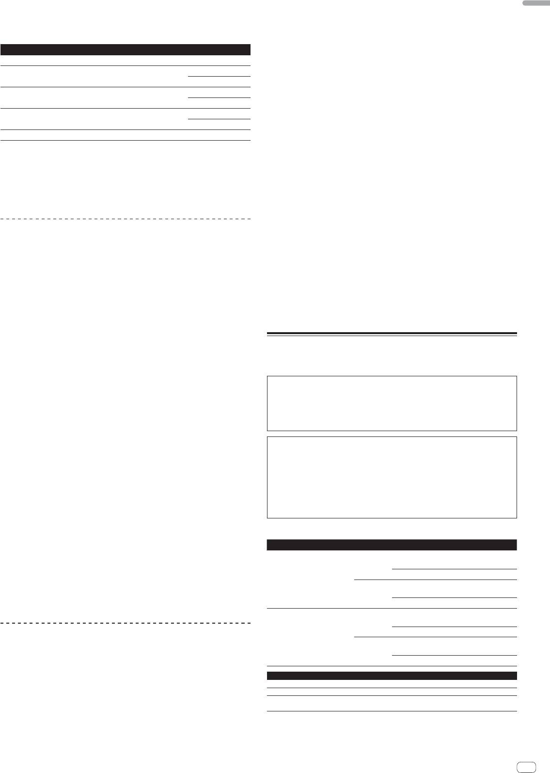
10 Read the terms of the license agreement carefully, and if
The personal information input when registering a new user account may
you agree, select [I agree to the license terms and conditions],
be collected, processed and used based on the privacy policy on the Serato
website.
then click [Install].
8 Click the link in the e-mail message sent from “Serato.com”.
This takes you to the Serato DJ download page. Proceed to step 9.
9 Log in.
Input the e-mail address and password you have registered to log in to “Serato.com”.
10 Download the Serato DJ software from the download
page.
Unzip the downloaded file, then double-click the unzipped file to launch the installer.
If you do not agree to the contents of the usage agreement, click [Close] to
cancel installation.
Installation begins.
8
En
11 Read the terms of the license agreement carefully, and if
English
you agree, click [Agree].
If you do not agree to the contents of the usage agreement, click [Disagree]
to cancel installation.
12 If the following screen appears, drag and drop the [Serato
DJ] icon on the [Applications] folder icon.
En
9
Connections
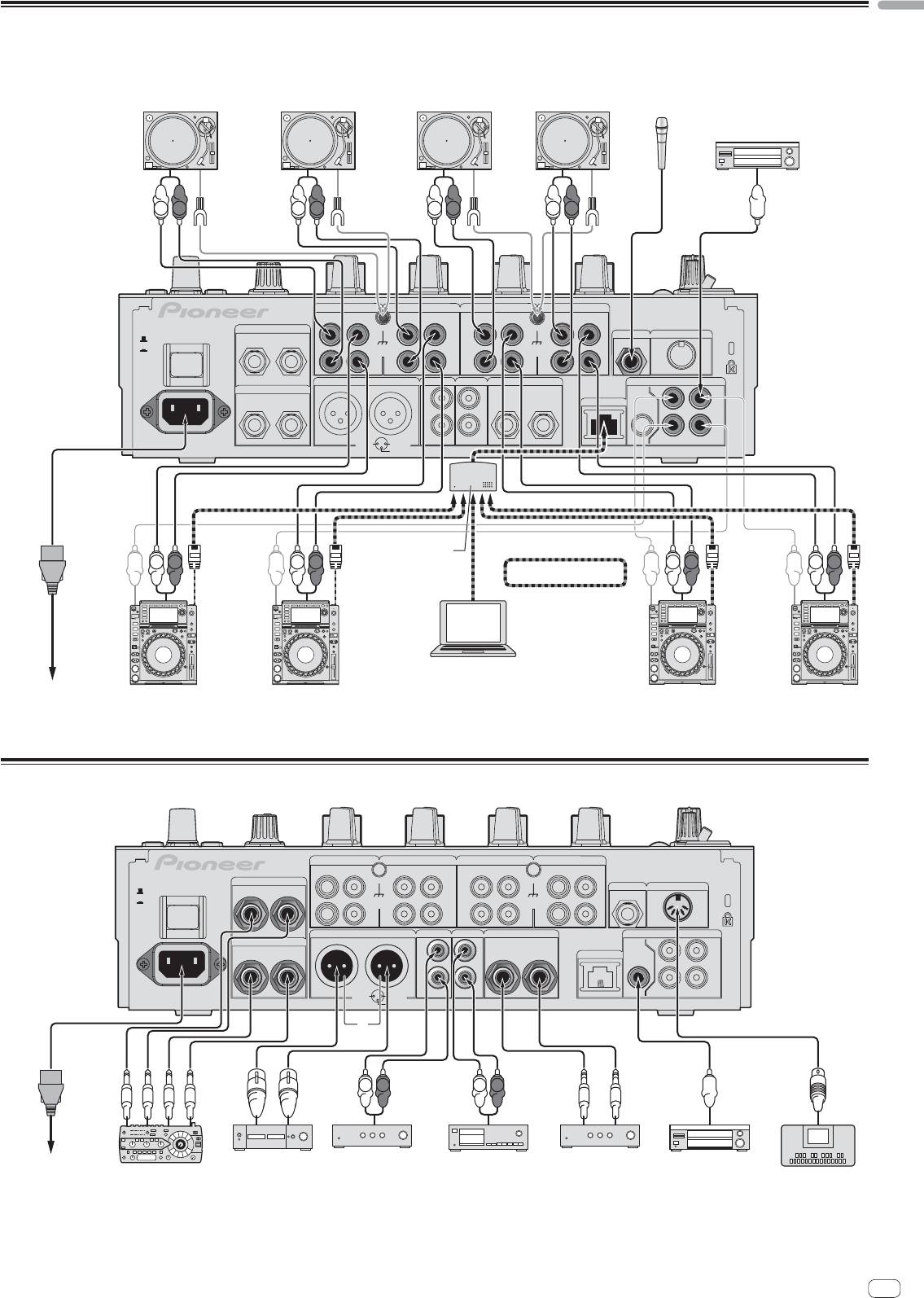
Be sure to turn off the power and unplug the power cord from the power outlet whenever making or changing connections.
Connect the power cord after all the connections between devices have been completed.
Be sure to use the included power cord.
Refer to the operating instructions for the component to be connected.
When creating a DVS (Digital Vinyl System) combining a computer, audio interface, etc., be careful in connecting the audio interface to this unit’s input terminals and in
the settings of the input selector switches.
Also refer to the operating instructions of the DJ software and audio interface.
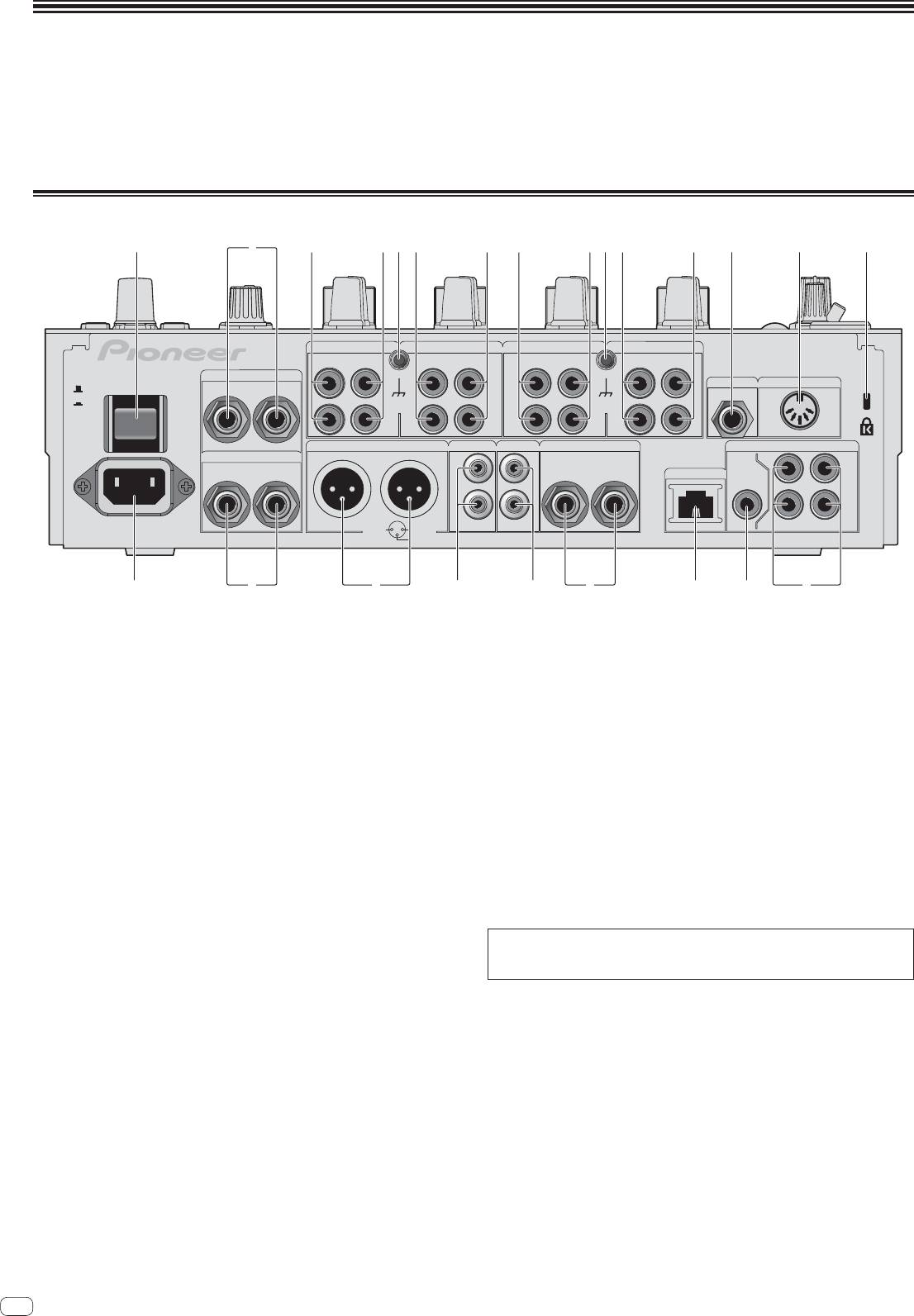
Rear panel
1 34 3443 435 5 6 7 82
CH 4 CH 3
CH 2
CH 1
PHONO PHONO PHONO
CD/ LINE
CD/ LINE
CD/ LINE
PHONO
CD/ LINE
L
L
L
L
RETURN
R
L
(MONO)
MIC2
MIDI OUT
OFF
POWER
ON
SIGNAL GND SIGNAL GND
R
R
R
R
MASTER1 MASTER2
REC OUT
BOOTH
DIGITAL
SEND
R
L
L
L
TRS
CH1CH2
LR
(MONO)
R
L
LINK
MASTER
OUT
IN
R
R
AC IN
CH4
CH3
1 GND
2 HOT
3 COLD
de abh 9cg f
1 POWER button (page 14)
c BOOTH terminals (page 11)
Turns this unit’s power on and off.
These are output terminals for a booth monitor.
2 RETURN terminals (page 11)
d REC OUT terminals (page 11)
Connect to the output terminal of an external effector. When the [L (MONO)]
These are output terminals for recording.
channel only is connected, the [L (MONO)] channel input is simultaneously
input to the [R] channel.
e MASTER2 terminals (page 11)
Connect to a power amplifier, etc.
3 PHONO terminals (page 11)
Connect to a phono level (MM cartridge) output device. Do not input line level
f MASTER1 terminals (page 11)
signals.
Connect to a power amplifier, etc.
To connect a device to the [PHONO] terminals, remove the short-circuit pin plug
Be sure to use these as balanced outputs. Be careful not to accidentally
inserted in the terminals.
insert the power cord of another unit.
Insert this short-circuit pin plug into the [PHONO] terminals when nothing is
g SEND terminals (page 11)
connected to them to cut external noise.
Connect to the input terminal of an external effector. When the [L (MONO)]
4 CD/LINE terminals (page 11)
channel only is connected, a monaural audio signal is output.
Connect to a DJ player or a line level output component.
h AC IN
5 SIGNAL GND terminal (page 11)
Connects to a power outlet using the included power cord. Wait until all connec-
Connects an analog player’s ground wire here. This helps reduce noise when the
tions between the equipment are completed before connecting the power cord.
analog player is connected.
Be sure to use the included power cord.
WARNING
6 MIC2 terminal (page 11)
The short-circuit pin plugs out of the reach of children and infants. If accidentally
Connects a microphone here.
swallowed, contact a doctor immediately.
7 MIDI OUT terminal (page 11)
Connects this to the MIDI IN terminal on an external MIDI sequencer.
8 Kensington security slot
9 DIGITAL IN terminal (page 11)
Connect these to the digital coaxial output terminals on DJ players, etc. The
sound may be momentarily interrupted when the output signal sampling fre-
quency is switched.
a DIGITAL MASTER OUT terminal (page 11)
Outputs the master channel audio signals.
b LINK terminal (page 11)
Connect these to the LINK terminals on Pioneer DJ players or the LAN ports of
computers on which rekordbox is installed (PRO DJ LINK).
To connect multiple devices, use a switching hub (commercially available).
Use a 100Base-TX-compatible switching hub. Some switching hubs may not
operate properly.
10
En
English
Connecting input terminals
When creating a DVS (Digital Vinyl System) combining a computer, audio interface, etc., be careful in connecting the audio interface to this unit’s input terminals and in
the settings of the input selector switches.
Also refer to the operating instructions of the DJ software and audio interface.
Analog player Analog player Analog player
Analog player
Microphones
Digital audio output device
L
R
L
R
L
R
L
R
CH 4 CH 3
CH 2
CH 1
PHONO PHONO PHONO
CD/ LINE
CD/ LINE
CD/ LINE
PHONO
CD/ LINE
RETURN
L
L
L
L
R
L
(MONO)
MIC2
MIDI OUT
OFF
POWER
ON
SIGNAL GND SIGNAL GND
R
R
R
R
MASTER1 MASTER2
REC OUT
BOOTH
DIGITAL
SEND
R
L
L
L
TRS
CH1CH2
LR
(MONO)
R
L
LINK
MASTER
OUT
IN
R
R
AC IN
1 GND
2 HOT
CH4
CH3
3 COLD
Switching hub
L
R
L
R
L
R
L
R
PRO DJ LINK
1
rekordbox
Computers
2
To power outlet
Pioneer DJ players
Pioneer DJ players
2
1 For details on PRO DJ LINK, see About PRO DJ LINK on page 15.
2 To use the fader start function with PRO DJ LINK, connect a LAN cable (page 16).
Connecting output terminals
CH 4 CH 3
CH 2
CH 1
PHONO
CD/ LINE
CD/ LINEPHONO
CD/ LINEPHONO
PHONO
CD/ LINE
RETURN
L
L
L
L
MIC2
MIDI OUT
OFF
POWER
R
L
(MONO)
ON
SIGNAL GND SIGNAL GND
R
R
R
R
MASTER1 MASTER2
REC OUT
BOOTH
DIGITAL
SEND
R
L
L
L
TRS
CH1CH2
LR
(MONO)
R
L
LINK
MASTER
OUT
IN
R
R
AC IN
CH3
1 GND
2 HOT
CH4
3 COLD
3
L
R
L
R
To power outlet
Power amplifier
2
Power amplifier
2
Cassette deck, etc.
Power amplifier
Digital audio
External effector
1
(analog input recording device)
(for booth monitor)
input device
MIDI sequencer
1 Also connect the external effector to the [RETURN] terminal (input terminal).
2 Be sure to use the [MASTER1] terminals only for a balanced output. Connection with an unbalanced input (such as RCA) using an XLR to RCA converter cable (or con-
verter adapter), etc., may lower the sound quality and/or result in noise.
For connection with an unbalanced input (such as RCA), use the [MASTER2] terminals.
3 Be careful not to accidentally insert the power cord of another unit to [MASTER1] terminal.
En
11
Connecting to the control panel
12
En
B
CD/ LINE PHO
DIGITAL
TRIM
OVER
10
MIC 1
7
0
LEVEL
4
HI
MIC 2
2
0
1
MIXING
CUE
MASTER
LEVEL
A THRU
0
PHONES
0
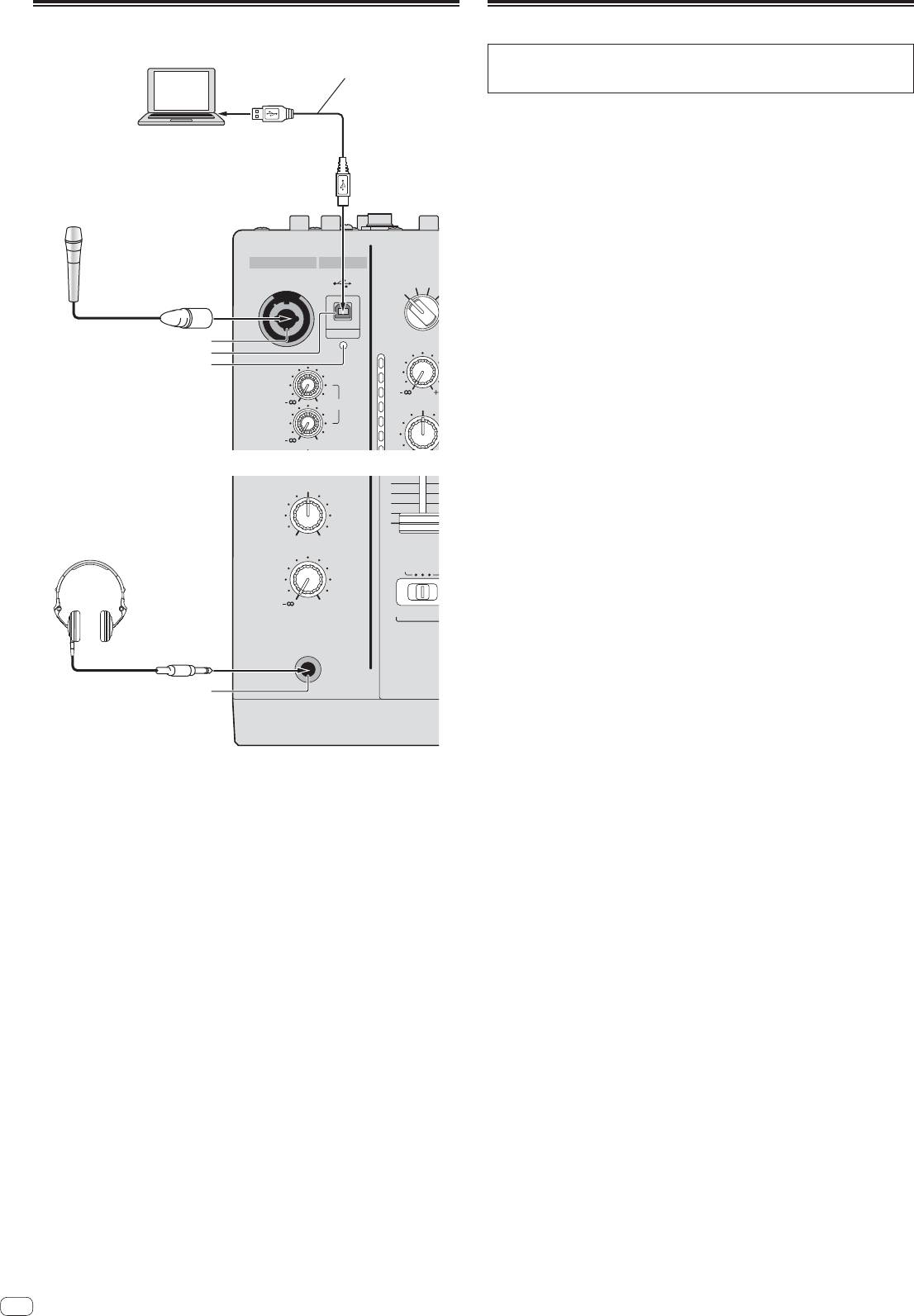
Connecting this unit and computer
Be sure to connect using the
For instructions on operating in combination with Serato DJ, see the “Quick Start
Computers
included USB cable.
Guide – Serato DJ Edition”. For details, see Downloading the latest versions of the
operating instructions and the Quick Start Guide - Serato DJ Edition (p.28).
1 Connect this unit to your computer via a USB cable.
This unit functions as an audio device conforming to the ASIO standards.
This operation does not work with computers that do not support USB 2.0.
When using ASIO-compatible applications, [USB DECK 3], [USB DECK 1], [USB
DECK 2] and [USB DECK 4] can be used as inputs.
When using DirectX-compatible applications, only [USB DECK 3] can be used as
the input.
The computer’s recommended operating environment depends on the DJ appli-
cation. Be sure to check the recommended operating environment for the DJ
application you are using.
MIC USB
Microphones
When another USB audio device is connected to the computer at the same time,
MIC1
it may not operate or be recognized normally.
We recommend only connecting the computer and this unit.
When connecting the computer and this unit, we recommend connecting
directly to this unit’s USB port.
1
2
2 Press [POWER] button.
3
Turn on the power of this unit.
For Windows
— The message [Installing device driver software] may appear when this
unit is first connected to the computer or when it is connected to a different
USB port on the computer. Wait a while until the message [Your devices
are ready for use] appears.
When installing on Windows XP
— [Can Windows connect to Windows Update to search for software?]
may appear while the installation is in progress. Select [No, not this time],
then click [Next] to continue installation.
— [What do you want the wizard to do?] may appear while the instal-
lation is in progress. Select [Install the software automatically
(Recommended)], then click [Next] to continue installation.
— If [Windows Security] appears on the screen while the installation is in
progress, click [Install this driver software anyway] and continue with the
installation.
Headphones
4
1 MIC1 terminal (page 15)
Connects a microphone here.
2 USB terminal (page 12)
Connect the computer.
3 USB connection indicator
Lights when signals are being exchanged with the computer.
4 PHONES terminal (page 14)
Connect headphones here.
English
Operation
Control Panel
POWER
s
MIC MASTER MIDI
USB
b b b b
t
ON/ OFF LFO FORM
START
MIC1
CD/ LINE PHONO
CD/ LINE PHONO
CD/ LINE PHONO
CD/ LINE PHONO
/STOP
LEVEL
DIGITAL
USB
DIGITAL
USB
DIGITAL
USB
DIGITAL
USB
u
DECK
3
DECK
1
DECK
2
DECK
4
UTILITY
WAKE UP
k
c
c
c
c
BEAT EFFECTS
0
TRIM
TRIM
TRIM
TRIM
l
OVER
OVER
OVER
OVER
OVER
CH SELECT
d
d
d
d
1 2 3 4
1
10
10
10
10
10
MIC 1
7
e
MIC MST
A B
9
7
9
e
7
9
e
7
9
e
7
PARAMETER
v
0
LEVEL
4
HI
4
HI
4
HI
4
HI
4
AUTO
GRID
TA P
BPM
2
MIC 2
2
2
2
2
2
%
ms
0
1
1
1
1
1
0
0
0
0
0
-
26
/
6
-
26
/
6
-
26
/
6
-
26
/
6
HI
-
1
MID
-
1
MID
-
1
MID
-
1
MID
-
1
-
2
-
2
-
2
-
2
-
2
X
-
PAD
3
12 12
EQ
-
3
EQ /
-
3
EQ /
-
3
EQ /
-
3
EQ /
-
3
ISO
ISO
ISO
ISO
LOW
-
5
-
5
-
5
-
5
-
5
w
12 12
-
7
-
26
/
6
-
7
-
26
/
6
-
7
-
26
/
6
-
7
-
26
/
6
-
7
TALK
OFF
ON
OVER
-
10
LOW
-
10
LOW
-
10
LOW
-
10
LOW
-
10
x
-
15
-
15
-
15
-
15
-
15
BEAT
-
24
-
24
-
24
-
24
-
24
y
4
dB
-
26
6
dB
dB
/
-
26
/
6
-
26
/
6
dB
-
26
/
6
dB RL
AUTO
QUAN-
/ TAP
TAP
TIZE
f
f
f
f
z
SPACE
DUB
GATE/
COLOR
COLOR
COLOR
COLOR
BALANCE
ECHO
COMP
A
5
SOUND COLOR FX
g
g
g
g
m
CUE
6
NOISE
CRUSH FILTER
HILOW
HILOW
HILOW
HILOW
RL
FLANGER
PHASER
LINK
FILTER
ROBOT
CUE
6
CUE
6 6 6
CUE
CUE
6
CUE
MELODICTRANS
REVERB
6
CUE
SLIP ROLL
SPIRAL
ROLL
B
MONO STEREO
ECHO
REV ROLL
FADER START
DELAY
MIDI LFO
SND/ RTN
7
1
2 3 4
n
4
MIC
3
CF.A
10
10
10
2
CF.B
HEADPHONES
9
9
9
BOOTH MONITOR
1
MASTER
C
MONO SPLIT
STEREO
8
8
8
7
7
7
8
6
6
6
o
5
5
5
TIME
MIXING
4
4
4
3
3
3
0
2
2
2
D
9
1
1
1
EQ CURVE
EQISOLATOR
000
h
h
h
h
CUE
MASTER
p
LEVEL
LEVEL / DEPTH
BA THRU
BA THRU
BA THRU
BA THRU
CH FADER
a
E
i
i
i
i
q
0
MIN
MAX
CROSS FADER
CROSS FADER ASSIGN
ON/ OFF
PHONES
r
F
AB
j
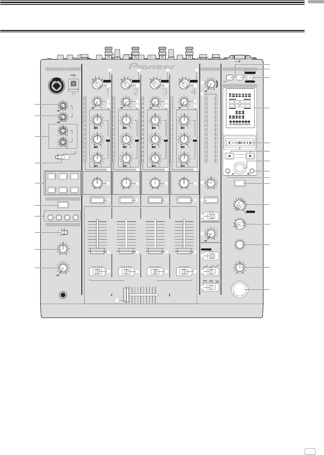
1 MIC1 LEVEL control (page 15)
9 MIXING control (page 14)
Adjusts the sound level output from the [MIC1] channel.
This adjusts the monitor volume balance of the sound of channels for which the
[CUE] button is pressed and the sound of the [MASTER] channel.
2 MIC2 LEVEL control (page 15)
Adjusts the sound level output from the [MIC2] channel.
a LEVEL control (page 14)
Adjusts the sound level output from the headphones.
3 EQ (HI, LOW) controls (page 15)
These adjust the tone quality of the [MIC1] and [MIC2] channels.
b USB audio input indicator
Lights when sound is being input from the computer to the various channels.
4 OFF, ON, TALK OVER selector switch (page 15)
Turns the microphone on/off.
c Input selector switches (page 14)
Selects the input source of each channel from the components connected to
5 SOUND COLOR FX buttons (page 16)
this unit.
These turn the SOUND COLOR FX effects on/off.
d TRIM control (page 14)
6 CUE button (page 14)
Adjusts the level of audio signals input in each channel.
Presses the [CUE] button(s) for the channel(s) you want to monitor.
e EQ/ISO (HI, MID, LOW) controls (page 14)
7 FADER START (1, 2, 3, 4) buttons (page 16)
These adjust the sound quality of the respective channels.
These turn the fader start function on/off.
f Channel Level Indicator (page 14)
8 MONO SPLIT, STEREO selector switch (page 14)
Displays the sound level of the respective channels before passing through the
Switches how the monitor sound output from the headphones is distributed.
channel faders.
En
13
g COLOR control (page 16)
This changes the parameters of the SOUND COLOR FX of the different channels.
Basic Operation
h Channel Fader (page 14)
Adjusts the level of audio signals output in each channel.
Outputting sound
i CROSS FADER ASSIGN (A, THRU, B) selector switch (page 14)
Sets the output destination of each channel to [A] or [B].
1 Press [POWER] button.
j Crossfader (page 14)
Turn on the power of this unit.
Outputs audio signals assigned by the crossfader assign switch correspond-
ing to the curve characteristics selected by [CROSS FADER] (Crossfader Curve
2 Switch the input selector switches.
Selector Switch).
Selects the input sources for the different channels from among the devices con-
nected to this unit.
k MASTER LEVEL control (page 14)
— [DIGITAL]: Selects the DJ player connected to the [DIGITAL] terminals.
Adjusts the audio level output from the [MASTER1] and [MASTER2] terminals.
— [PHONO]: Selects the analog player connected to the [PHONO] terminals.
— [CD/LINE]: Selects the cassette deck or CD player connected to the [CD/
l Master Level Indicator (page 14)
LINE] terminals.
Displays the audio level output from the [MASTER1] and [MASTER2] terminals.
— [USB]: Selects the sound of the computer connected to the [USB] port.
m BALANCE control (page 15)
3 Turn the [TRIM] control.
Adjusts the left/right balance of the sound output from the [MASTER1] termi-
Adjusts the level of audio signals input in each channel.
nals, etc.
The corresponding channel level indicator lights when audio signals are being
n MONO, STEREO selector switch (page 15)
properly input to that channel.
Switches the sound output from the [MASTER1] terminals, etc., between mon-
4 Move the channel fader away from you.
aural and stereo.
Adjusts the level of audio signals output in each channel.
o BOOTH MONITOR control (page 15)
5 Switch the [CROSS FADER ASSIGN (A, THRU, B)] selector
Adjusts the level of audio signals output from the [BOOTH] terminal.
switch.
p EQ CURVE (ISOLATOR, EQ) selector switch (page 14)
Switches the output destination of each channel.
Switches the function of the [EQ/ISO (HI, MID, LOW)] controls.
— [A]: Assigns to [A] (left) of the crossfader.
— [B]: Assigns to [B] (right) of the crossfader.
q CH FADER ( , , ) selector switch (page 15)
— [THRU]: Selects this when you do not want to use the crossfader. (The sig-
Switches the channel fader’s curve characteristics.
nals do not pass through the crossfader.)
r CROSS FADER ( , , ) selector switch (page 15)
6 Set the crossfader.
This switches the crossfader curve characteristics.
This operation is not necessary when the [CROSS FADER ASSIGN (A, THRU, B)]
selector switch is set to [THRU].
s ON/OFF (UTILITY) button
— ON/OFF: Turns the MIDI function on/off (page 17).
7 Turn the [MASTER LEVEL] control.
— UTILITY: Displays the [USER SETUP] or [CLUB SETUP] screen (page 24).
Audio signals are output from the [MASTER1] and [MASTER2] terminals.
The master level indicator lights.
t START/STOP button (page 18)
Sends the MIDI start/MIDI stop signals.
u LFO FORM (WAKE UP) button
Adjusting the sound quality
— LFO FORM: When [MIDI LFO] is selected at BEAT EFFECT, the MIDI signal’s
waveform switches each time the button is pressed (page 20).
1 Switch the [EQ CURVE (ISOLATOR, EQ)] selector switch.
— WAKE UP: Cancels the auto standby mode.
— [ISOLATOR]: Functions as an isolator.
— [EQ]: The equalizer function is set.
v Main unit display
2 Turn the [EQ/ISO (HI, MID, LOW)] controls for the respective
w X-PAD (page 17)
Adjusts the quantitative parameter of the BEAT EFFECT function.
channels.
The adjustable ranges for the respective controls are as shown below.
x BEAT , buttons (page 16)
— HI: –26 dB to +6 dB (13 kHz)
Set the beat fraction for synchronizing the effect sound.
— MID: –26 dB to +6 dB (1 kHz)
— LOW: –26 dB to +6 dB (70 Hz)
y TAP (ENTER) button
— TAP: When the BPM measurement mode is set to [TAP], the BPM is input
manually by tapping the button with a finger (page 16).
Monitoring sound with headphones
— ENTER: Used to change this unit’s settings (page 24).
z QUANTIZE button
1 Connect headphones to the [PHONES] terminal.
When the QUANTIZE function is turned on for BEAT EFFECT, the effect is applied
to the sound without going off tempo when the currently playing track. (page 15).
2 Press the [CUE] button(s) for the channel(s) you want to
monitor.
A AUTO/TAP button (page 16)
Switches the BPM measurement mode.
3 Switch the [MONO SPLIT, STEREO] selector switch.
— [MONO SPLIT]: The sound of the channels for which the [CUE] button is
B Beat effect selector switch (page 16)
pressed is output from the headphones output’s left channel, the [MASTER]
Switches the BEAT EFFECT effect type.
channel sound is output from the right channel.
C Effect channel selector switch (page 16)
— [STEREO]: The sound of the channels for which the [CUE] button is pressed
Switches the channel to which the BEAT EFFECT is to be applied.
is output from the headphones in stereo.
D TIME control (page 16)
4 Turn the [MIXING] control.
Adjusts the BEAT EFFECT’s time parameter.
This adjusts the monitor volume balance of the sound of channels for which the
[CUE] button is pressed and the sound of the [MASTER] channel.
E LEVEL/DEPTH control (page 16)
Adjusts the BEAT EFFECT’s quantitative parameter.
5 Turn the [LEVEL] control for [HEADPHONES].
The sound of the channels for which the [CUE] button is pressed is output from the
F ON/OFF button (page 16)
headphones.
Turns the BEAT EFFECT function on/off.
When the [CUE] button is pressed again, monitoring is canceled.
Do not pull on the channel fader and crossfader knobs with excessive force. The
knobs have a structure by which they cannot be pulled off easily. Pulling the knobs
strongly may result in damaging the unit.
14
En
English
Switching the fader curve
Audio is output from the [BOOTH] terminal
Turn the [BOOTH MONITOR] control.
䢢 Select the channel fader curve characteristics
Adjusts the level of audio signals output from the [BOOTH] terminal.
Switch the [CH FADER ( , , )] selector switch.
— [ ]: The curve rises suddenly at the back side.
Advanced Operations
— [ ]: A curve between the ones above and below is set.
— [
]: The curve rises gradually (the sound gradually increases as the chan-
nel fader is moved away from the front side).
Using Serato DJ-supported functions
䢢 Select the crossfader curve characteristics
When this unit and a computer on which Serato DJ is running are connected by
USB cable, the functions below can be used.
Switch the [CROSS FADER ( , , )] selector switch.
— [ ]: Makes a sharply increasing curve (if the crossfader is moved away
䢢 QUANTIZE
from the [A] side, audio signals are immediately output from the [B] side).
— [ ]: Makes a curve shaped between the two curves above and below.
When tracks that have been analyzed with Serato DJ are used, tracks are put on
— [ ]: Makes a gradually increasing curve (if the crossfader is moved away
beat even if the [BEAT EFFECTS] [ON/OFF] button is pressed or the [X-PAD] is
from the [A] side, the sound on the [B] side gradually increases, while the
touched roughly.
sound on the [A] gradually decreases).
䢢 FADER START
Using a microphone
Playback of tracks in Serato DJ can be started by operating this unit’s fader (Fader
Start Play).
1 Connect a microphone to the [MIC1] or [MIC2] terminal.
2 Set the [OFF, ON, TALK OVER] selector switch to [ON] or
About PRO DJ LINK
[TALK OVER].
When a Pioneer DJ player supporting PRO DJ LINK (e.g. CDJ-2000nexus, CDJ-2000,
— [ON]: The indicator lights.
CDJ-900), a computer on which rekordbox is installed and this unit are connected by
— [TALK OVER]: The indicator flashes.
LAN cable, the PRO DJ LINK functions below can be used.
When set to [TALK OVER], the sound of channels other than the [MIC] channel
For more details on the PRO DJ LINK function, also refer to the DJ player’s handling
is attenuated by 18 dB (default) when a sound of –10 dB or greater is input to the
instructions and rekordbox’s operating instructions.
microphone.
For instructions on connections, see Connecting input terminals on page 11.
The [TALK OVER] sound attenuation level can be changed at [USER SETUP]. For
When connected using a switching hub, up to 4 DJ players and 2 computers can
instructions on changing this, see Changing the settings on page 24.
be connected.
The talk over mode can be switched to the normal mode or the advanced mode.
Use a 100Base-TX-compatible switching hub. Some switching hubs may not
For instructions on changing it, see Changing the settings on page 24.
operate properly.
Set the DJ player’s player number to the same number as the channel to which
3 Turn the [MIC1 LEVEL] or [MIC2 LEVEL] control.
the audio cable is connected.
Adjust the level of the sound output from the [MIC] channel.
Pay attention that rotating to the extreme right position outputs a very loud
sound.
䢢 QUANTIZE
When tracks analyzed with rekordbox are used, the track is put on beat even when
4 Input audio signals to the microphone.
the [ON/OFF] button of [BEAT EFFECTS] is pressed or the [X-PAD] is touched
roughly.
䢢 Adjusting the sound quality
䢢 FADER START
Turn the [MIC] channels’ [EQ (HI, LOW)] controls.
Playback on the DJ player can be started by operating this unit’s fader (Fader Start
The adjustable ranges for the respective controls are as shown below.
Play).
— HI: –12 dB to +12 dB (10 kHz)
— LOW: –12 dB to +12 dB (100 Hz)
䢢 LINK MONITOR
With this function, rekordbox music files stored on the computer can be quickly
Switching between monaural and stereo audio
monitored over the headphones.
This switches the sound output from the [MASTER1], [MASTER2], [BOOTH], [REC
OUT], [PHONES], [DIGITAL MASTER OUT] and [USB] terminals between monaural
䢢 STATUS INFORMATION
and stereo.
To adjust the sound output from the [USB] terminals, select [MIX (REC OUT)] at
This function informs the DJ players of the connected channel status (on-air status,
[Mixer Audio Output] in the setting utility.
channel number, etc.).
Switch the [MONO, STEREO] selector switch.
— [MONO]: Outputs monaural audio.
Using the QUANTIZE function
— [STEREO]: Outputs stereo audio.
Effects can be applied to the sound in tempo with the currently playing track
based on the GRID information of tracks that have been analyzed with Serato DJ or
䢢 Adjusting the L/R balance of audio
rekordbox.
The left/right balance of the sound output from the [MASTER1], [MASTER2],
To use the QUANTIZE function with PRO DJ LINK, connect this unit and a PRO DJ
[BOOTH], [REC OUT], [PHONES], [DIGITAL MASTER OUT] and [USB] terminals can
LINK-compatible Pioneer DJ player beforehand. For instructions on connecting, see
be adjusted.
Connecting input terminals on page 11.
To adjust the sound output from the [USB] terminals, select [MIX (REC OUT)] at
In addition, music files must have been analyzed with rekordbox beforehand in order
[Mixer Audio Output] in the setting utility.
to use the QUANTIZE function. For instructions on analyzing music files with rekord-
box, also see rekordbox’s operating instructions.
1 Set the [MONO, STEREO] selector switch to [STEREO].
When using in combination with the CDJ-2000nexus, first update the firmware
to version 1.02 or later.
2 Turn the [BALANCE] control.
To use in combination with the CDJ-2000 or CDJ-900, first update the firmware to
The sound’s left/right balance changes according to the direction in which the
version 4.0 or later.
[BALANCE] control is turned and its position.
Rotating to the rightmost position outputs only the right sound of stereo audio.
1 Press the [QUANTIZE] button.
Rotating to the leftmost position outputs only the left sound of stereo audio.
The QUANTIZE function turns on.
[GRID] lights on this unit’s main unit display when the GRID information has been
properly received from Serato DJ or the DJ player and the QUANTIZE function can
be used. [GRID] flashes if the GRID information has not been properly received.
En
15
Depending on the playing status of Serato DJ or the DJ player (off air, scratch-
1 Connect headphones to the [PHONES] terminal.
ing, playing in reverse, etc.), it may not be possible to receive the GRID
information.
2 Connect a computer on which rekordbox is installed.
For instructions on connections, see Connecting input terminals on page 11.
2 Press the [ON/OFF] button of [BEAT EFFECTS] or touch the
[X-PAD].
3 Selecting the track to be monitored with rekordbox.
The effect is added to the sound in tempo with the track being played.
4 Press the [CUE] button for [LINK].
When the [QUANTIZE] button is pressed again, the QUANTIZE function turns
The track selected with rekordbox is output from the headphones.
off.
When the [CUE] button is pressed again, monitoring is canceled.
The same operation as at Monitoring sound with headphones (steps 3 to 5) can
be performed.
Using the FADER START function
When this unit and a computer on which Serato DJ is running are connected by
USB cable, such operations as starting playback of tracks in Serato DJ can be con-
Using the SOUND COLOR FX function
trolled using this unit’s fader.
These are effects that change in association with the [COLOR] control.
Connect this unit and a computer on which Serato DJ is running beforehand.
In the same way, when this unit and a Pioneer DJ player are connected by LAN
1 Press one of the [SOUND COLOR FX] selection buttons.
cable, such operations as starting playback of the DJ player can be controlled using
This selects the type of effect.
this unit’s fader.
The button that was pressed flashes.
Connect the Pioneer DJ player and this unit beforehand. For instructions on con-
Even if one of the [SOUND COLOR FX] selection buttons is already selected,
necting, see Connecting input terminals on page 11.
when a different button is selected and pressed, that button is selected.
For instructions on setting the player numbers of Pioneer DJ players, see About PRO
For the types of effects, see Types of SOUND COLOR FX effects on page 19.
DJ LINK on page 15.
The same effect is set for [CH1] to [CH4].
The fader start function can be switched on and off for all DJ players all at once. For
the switching procedure, see Changing the settings on page 24.
2 Turn the [COLOR] control.
The FADER START function cannot be used when attempting to perform
The effect is applied to the channel(s) for which the control(s) was (were) pressed.
DVS control while Serato DJ is set to the Absolute mode. When one of the
[FADER START (1, 2, 3, 4)] buttons is pressed while the Absolute mode is set,
that button flashes then turns off.
䢢 Canceling the SOUND COLOR FX effect
䢢 Start playback using the channel fader
Press the [SOUND COLOR FX] selection button that is flashing.
The effect is canceled.
1 Set the [CROSS FADER ASSIGN (A, THRU, B)] selector switch
to [THRU].
Using the BEAT EFFECT function
2 Press one of the [FADER START (1, 2, 3, 4)] buttons.
This function lets you instantaneously set various effects according to the tempo
Select the channel to be started with the fader start function.
(BPM = Beats Per Minute) of the currently playing track.
For Serato DJ
— [Fader Start 1] button: Selects [DECK 3].
Main unit display
— [Fader Start 2] button: Selects [DECK 1].
— [Fader Start 3] button: Selects [DECK 2].
1
— [Fader Start 4] button: Selects [DECK 4].
CH SELECT
3 Set the channel fader to the nearest position towards you.
2
1 2 3 4
4 Set a cue in Serato DJ or on the DJ player.
MIC MST
A B
The track cues to the cue point and the pause mode is set.
PARAMETER
4
AUTO
5
5 Move the channel fader away from you.
3
GRID
TAP BPM
6
Playback of the track in Serato DJ or the DJ player starts.
%
If you set the channel fader back to the original position, the player instanta-
7
8
ms
neously returns to the cue point already set and pauses playback (back cue).
9
䢢 Start playback using the crossfader
a
Effect display
1
The name of the selected effect is displayed.
1 Set the [CROSS FADER ASSIGN (A, THRU, B)] selector switch
section
Channel select
to [A] or [B].
2
The name of the channel to which the effect is applied is displayed.
display section
[AUTO] lights when the BPM measurement mode is set to the auto
2 Press one of the [FADER START (1, 2, 3, 4)] buttons.
3
AUTO (TAP)
mode.
Select the channel to be started with the fader start function.
[TAP] lights when in the manual input mode.
For Serato DJ
When in the auto mode, this displays the automatically detected
— [Fader Start 1] button: Selects [DECK 3].
BPM value.
— [Fader Start 2] button: Selects [DECK 1].
BPM value display
When the BPM cannot be detected, the previously detected BPM
4
— [Fader Start 3] button: Selects [DECK 2].
(3 digits)
value is displayed and flashes.
When in the manual input mode, this displays the BPM value that
— [Fader Start 4] button: Selects [DECK 4].
was input manually.
This lights when Serato DJ is running and the QUANTIZE func-
3 Set the crossfader.
tion can be used. It also lights when playing a track that has been
Set to the edge opposite the side on which the channel you want to use with the
5
GRID
analyzed with rekordbox and the QUANTIZE function can be used
fader start function is set.
in combination with the DJ player. It flashes or is off when the
QUANTIZE function cannot be used.
4 Set a cue in Serato DJ or on the DJ player.
6
BPM
This is always lit.
The track cues to the cue point and the pause mode is set.
This displays the parameters specified for the individual effects.
When the [BEAT , ] button is pressed, the corresponding beat
5 Set the crossfader.
Parameter display
fraction is displayed for 1 second.
7
Playback of the track in Serato DJ or the DJ player starts.
section
When a value outside the parameter range is specified with the
If you set the crossfader back to the original position, the player instantaneously
[BEAT , ] button, the value does not change and the display
flashes.
returns to the cue point already set and pauses playback (back cue).
8
% (ms) These light according to the units for the different effects.
Beat display
9
This lights according to the selected beat number position.
section
Using the LINK MONITOR function
Touch display
a
This lights when the [X-PAD] is touched.
section
Check [Use “LINK MONITOR” of Pioneer DJ Mixers.] at [File] > [Preferences]
> [Audio] in rekordbox beforehand. Also refer to the rekordbox operating
1 Press [AUTO/TAP] button.
instructions.
Select the BPM measurement mode.
16
En
— [AUTO]: The BPM is measured automatically from the audio signal that is
䢢 Operating procedure 2
English
being input. The [AUTO] mode is set when this unit’s power is turned on.
— [TAP]: The BPM is input manually by tapping the [TAP] button with a finger.
1 Perform steps 1 to 5 of the Using the BEAT EFFECT function
The [AUTO] BPM measurement range is BPM = 70 to 180. With some tracks it
may not be possible to measure the BPM correctly. If the BPM cannot be mea-
procedure.
sured, the BPM value on the display flashes. In such cases, use the [TAP] button
to input the BPM manually.
2 Touch the [X-PAD].
The [X-PAD] changes the effect’s quantitative parameter.
2 Turn the beat effect selector switch.
This selects the type of effect.
For the types of effects, see Types of BEAT EFFECT on page 19.
Operating DJ software using the MIDI function
To use [SND/RTN], see Using the external effector below.
To use [MIDI LFO], see Using the MIDI LFO on page 17.
This unit outputs the operation information of buttons and controls in universal MIDI
format.
3 Turn the effect channel selector switch.
When connected by USB cable to a computer on which a MIDI-compatible DJ soft-
This selects the channel to which the effect is applied.
ware program is installed, the DJ software can be operated from this unit.
— [1] – [4]: The effect is applied to the sound of the respective channel.
Install the DJ software on your computer in advance. Also, adjust the audio and
— [MIC]: The effect is applied to the sound of [MIC] channel.
MIDI settings for the DJ software.
— [CF.A], [CF.B]: The effect is applied to the sound of the crossfader’s [A] (left)
For MIDI channel setting instructions, see Changing the settings on page 24.
or [B] (right) side.
For the messages output by this unit, see MIDI assignment map on page 22.
— [MASTER]: The effect is applied to the sound of the [MASTER] channel.
This operation is not necessary when [MIDI LFO] is selected.
1 Connect this unit’s [USB] terminal to the computer.
For details about connections, see Connecting to the control panel on page 12.
4 Press the [BEAT , ] button.
Set the beat fraction for synchronizing the effect sound.
2 Launch the DJ software.
The effect time corresponding to the beat fraction is set automatically.
3 Press the [ON/OFF (UTILITY)] button.
5 Press the [ON/OFF] button for [BEAT EFFECTS].
Turn the MIDI function on.
The effect is applied to the sound.
Transmission of the MIDI messages begin.
The effect’s time parameter can be adjusted by turning the [TIME] control.
When a fader or control is moved, a message corresponding to the position is
The effect’s quantitative parameter can be adjusted by turning the [LEVEL/DEPTH]
sent.
control.
When the [START/STOP] button is pressed and held in for more than 2 seconds,
The [ON/OFF] button flashes when the effect is on.
a set of MIDI messages corresponding to the button, fader or control positions is
When the [ON/OFF] button is pressed again, the effect turns off.
sent (Snapshot).
When the [ON/OFF (UTILITY)] button is pressed again, sending of the MIDI mes-
sages is stopped.
䢢 Inputting the BPM manually
The MIDI timing clock (BPM information) is sent regardless of the status of the
[ON/OFF (UTILITY)] button.
Tap the [TAP] button at least 2 times in rhythm with the beat
(in quarter notes) of the sound being played.
䢢 Making the preparations to use the MIDI LFO function
The average value of the interval at which the [TAP] button was tapped by finger is
set as the BPM.
The MIDI-compatible software, devices, etc. (referred to as the “MIDI signal recep-
When the BPM is set using the [TAP] button, the beat fraction is set to [1/1] and
tion side” below) must be prepared (“learned”) before using the MIDI LFO function.
the time of one beat (quarter note) is set as the effect time.
Perform the learning operations on the MIDI signal reception side.
The BPM can be set manually by turning the [TIME] control while pressing the
For the messages output by this unit, see MIDI assignment map on page 22.
[TAP] button.
1 Press the [ON/OFF (UTILITY)] button.
The BPM can be set in units of 0.1 by pressing the [AUTO/TAP] button while
Turn the MIDI function on.
pressing the [TAP] button and turning the [TIME] control while pressing the two
buttons.
2 Turn the beat effect selector switch.
Select [SND/RTN (MIDI LFO)].
䢢 Using the external effector
[S/RELFO] flashes on the effect display section, then [SND/RTN] is displayed.
3 Press the [ON/OFF] button for [BEAT EFFECTS].
1 Connect this unit and external effector.
Learn the [ON/OFF] button’s MIDI message of the [BEAT EFFECTS] in the MIDI
For instructions on connections, see Connecting output terminals on page 11.
signal reception side.
The MIDI message sent from the [ON/OFF] button of the [BEAT EFFECTS] dif-
2 Turn the beat effect selector switch.
fers when [SND/RTN (MIDI LFO)] is selected and when anything other than
Select [SND/RTN (MIDI LFO)].
[SND/RTN (MIDI LFO)] is selected.
The [ON/OFF] button’s MIDI message of [BEAT EFFECTS] when [SND/RTN
3 Turn the effect channel selector switch.
(MIDI LFO)] is selected is only sent when the operation is performed following
This selects the channel to which the effect is applied.
this procedure.
4 Press the [ON/OFF] button for [BEAT EFFECTS].
4 Press the [LFO FORM (WAKE UP)] button.
The sound that has passed through the external effector is output from the
Learn the [LFO FORM (WAKE UP)] button’s MIDI message in the MIDI signal recep-
[MASTER] channel.
tion side.
When the [ON/OFF] button is pressed again, the effect turns off.
[1/7 ] and [1/7 LFO] are displayed alternately on the effect display section.
If necessary, set the MIDI mapping for other buttons and controls.
Because the [LFO FORM (WAKE UP)] button’s MIDI message is sent sequen-
Operating the [X-PAD]
tially, depending on the MIDI signal reception side’s settings, it may not be
possible to learn the MIDI message.
Operating
[ON/OFF] button status of [BEAT
X-PAD
Effect
To set the MIDI mapping for other buttons and controls, press the
procedure
EFFECTS]
[LFO FORM(WAKE UP)] button to switch to [SND/RTN].
1
Off (lit)
Release K Touch Off K On
2
On (flashing)
Release K Touch On K On
䢢 Using the MIDI LFO
䢢 Operating procedure 1
Make the preparations following the procedure at Making the preparations to use the
MIDI LFO function beforehand.
1 Perform steps 1 to 4 of the Using the BEAT EFFECT function
1 Turn the beat effect selector switch.
procedure.
Select [SND/RTN (MIDI LFO)].
[S/RELFO] flashes on the effect display section, then [SND/RTN] is displayed.
2 Touch the [X-PAD].
The [X-PAD] turns the effect on and off and changes the quantitative parameter.
2 Press the [LFO FORM (WAKE UP)] button.
When you release your finger from the [X-PAD], the effect turns off.
Transmission of the MIDI signals begins.
To keep the effect on when you release your finger from the [X-PAD], while
The MIDI signal waveform pattern switches each time the [LFO FORM (WAKE UP)]
touching the [X-PAD] press the [ON/OFF] button of [BEAT EFFECTS], then
button is pressed.
release your finger from the [X-PAD].
En
17
[
SND/RTN
] [
1/7
] [
2/7
] [
3/7
]
7/7
]
6/7
][
5/7
][
[
4/7
][
3 Press the [BEAT , ] button.
Set the MIDI signal’s waveform output time.
4 Press the [ON/OFF] button of [BEAT EFFECTS] or touch the
[X-PAD].
The MIDI message for turning the effect on is sent.
When the [LFO FORM (WAKE UP)] button is pressed and a setting from
[1/7 ] – [7/7 ] is selected, the MIDI message for the buttons and con-
trols below can be sent even when the MIDI mode is turned off.
— [X-PAD] (Touch K Release)
— [CUE] button of [BEAT EFFECTS]
— Effect channel selector switch
— [LEVEL/DEPTH] control
— [ON/OFF] button of [BEAT EFFECTS]
When the [LFO FORM (WAKE UP)] button is pressed to switch between
[SND/RTN] and [MIDI LFO], BEAT EFFECT automatically turns off.
It is not possible to switch between [SND/RTN] and [MIDI LFO] while touching
the [X-PAD].
䢢 Sending the MIDI start and MIDI stop messages
Press the [START/STOP] button for [MIDI].
The MIDI start and MIDI stop messages are sent alternatively each time the
[START/STOP] button is pressed, regardless of whether the MIDI function is on
or off.
Operating an external MIDI sequencer
This unit outputs the operation information of buttons and controls in universal MIDI
format.
This unit sends the tempo of the currently playing source (BPM information) as the
MIDI timing clock. This can be used to synchronize an external MIDI sequencer with
the tempo of the source.
For the messages output by this unit, see MIDI assignment map on page 22.
External MIDI sequencers not supporting MIDI timing clocks cannot be
synchronized.
External MIDI sequencers cannot be synchronized for sources for which the
BPM cannot be measured stably.
The MIDI timing clock is output even with BPM values input manually by tapping
the [TAP] button with a finger. The MIDI timing clock output range is 40 BPM to
250 BPM.
1 Connect the [MIDI OUT] terminal to the external MIDI
sequencer’s MIDI IN terminal using a commercially available
MIDI cable.
2 Set the external MIDI sequencer’s sync mode to Slave.
3 Press the [START/STOP] button for [MIDI].
The MIDI start message is sent.
4 Press [ON/OFF] in the [MIDI] section.
Transmission of the MIDI messages begin.
18
En

English
Types of effects
LEVEL/DEPTH control (param-
Use this to set the balance between the original sound and the
Types of SOUND COLOR FX effects
eter 3)
echo sound.
X-PAD (parameter 4) Use this to set the delay time.
Effect Name Descriptions [COLOR] control
Turn counterclockwise: Applies the
reverberation effect to the mid- and
Applies a reverberation effect to
low ranges.
1
2
SPACE
SPIRAL
the original sound.
Turn clockwise: Applies the rever-
beration effect to the mid- and high
This function adds a reverberation effect to the input sound.
ranges.
When the delay time is changed, the pitch changes simultaneously.
Applies an echo effect, with the
Turn counterclockwise: Applies the
sound delayed slightly after the
echo effect to the mid-range only.
Input sound turned off
DUB ECHO
original sound output several
Turn clockwise: Applies the echo
times and gradually attenuated.
effect to the high range only.
Fade-out
Turn counterclockwise: A gate
effect makes the sound tighter,
Time
Changes the texture of the overall
with a reduced sense of volume.
1 beat
GATE/COMP
sound.
Turn clockwise: A compressor
Use these to set a time delay of 1/8 – 16/1 with respect to the
effect makes the sound fatter, with
BEAT , buttons (parameter 1)
time of one beat of the BPM.
an increased sense of volume.
Use this to set the delay time.
White noise generated inside
TIME control (parameter 2)
10 to 4000 (ms)
this unit is mixed in to the sound
Turn counterclockwise: The cut-
LEVEL/DEPTH control (param-
Use this to set the balance between the original sound and the
of the channel via the filter and
off frequency of the filter through
eter 3)
effect sound and to set the quantitative parameter.
output.
which the white noise passes
X-PAD (parameter 4) Use this to set the delay time.
The volume can be adjusted
gradually decreases.
NOISE
by turning the [TRIM]
Turn clockwise: The cut-off fre-
controls for the respective
quency of the filter through which
channels. The sound quality
the white noise passes gradually
1
2
can be adjusted by turning
REVERB
increases.
the [EQ/ISO (HI, MID, LOW)]
This function adds a reverberation effect to the input sound.
controls.
Turn counterclockwise: Increases
Direct sound
Early reflected sound
the sound’s distortion.
Changes the original sound to a
CRUSH
Turn clockwise: The sound is
Level
Reverberations
crushed-like sound for output.
crushed before passing through
1%
the high pass filter.
Turn counterclockwise: Gradually
decreases the low-pass filter’s
Time
Outputs sound that has passed
cutoff frequency.
FILTER
through a filter.
Turn clockwise: Gradually
increases the high-pass filter’s
100%
cutoff frequency.
Use these to set the extent of the reverberation effect, from
BEAT , buttons (parameter 1)
1 – 100 %.
Types of BEAT EFFECT
Use this to set the degree of the reverb effect.
TIME control (parameter 2)
1 – 100 (%)
LEVEL/DEPTH control (param-
Sets the balance between the original sound and the effect
eter 3)
sound.
1
X-PAD (parameter 4) Sets the filter’s cut-off frequency.
DELAY
A delay sound is output once according to the beat fraction set with the [BEAT ,
] buttons.
1
When 1/2 beat delay sound is added, 4 beats become 8 beats.
TRANS
Original
The sound is cut according to the beat fraction set with the [BEAT , ] buttons.
(4 beats)
Cut Cut
1/2 delay
(8 beats)
1/1 beat
Time
Use these to set a cut time of 1/16 – 16/1 with respect to the
Use these to set a time delay of 1/8 – 16/1 with respect to the
BEAT , buttons (parameter 1)
BEAT , buttons (parameter 1)
time of one beat of the BPM.
time of one beat of the BPM.
Use this to set the effect time.
Use this to set the delay time.
TIME control (parameter 2)
TIME control (parameter 2)
10 to 16000 (ms)
1 to 4000 (ms)
LEVEL/DEPTH control (param-
Sets the balance between the original sound and the effect
LEVEL/DEPTH control (param-
Use this to set the balance between the original sound and the
eter 3)
sound.
eter 3)
delay sound.
X-PAD (parameter 4) This sets the cut time.
X-PAD (parameter 4) Use this to set the delay time.
1
1
2
FILTER
ECHO
The filter’s cutoff frequency changes according to the beat fraction set with the
A delay sound is output several times and gradually attenuated according to the
[BEAT , ] buttons.
beat fraction set with the [BEAT , ] buttons.
With 1/1 beat echoes, the delay sounds are faded out according to the track’s tempo
even after the input sound has been cut.
Input sound turned off
Frequency
Fade-out
Use these to set the cycle for moving the cut-off frequency
BEAT , buttons (parameter 1)
as a time of 1/4 – 64/1 with respect to the time of one beat of
Time
1 beat
the BPM.
Use this to set the cycle at which the cut-off frequency is
Use these to set a time delay of 1/8 – 16/1 with respect to the
BEAT , buttons (parameter 1)
TIME control (parameter 2)
moved.
time of one beat of the BPM.
10 to 32000 (ms)
Use this to set the delay time.
TIME control (parameter 2)
LEVEL/DEPTH control (param-
The further the control is turned clockwise, the more the effect
1 to 4000 (ms)
eter 3)
is stressed.
En
19
The cycle at which the cut-off frequency is moved fluctuates
Use these to set an effect time of 1/16 – 16/1 with respect to
X-PAD (parameter 4)
BEAT , buttons (parameter 1)
finely.
the time of one beat of the BPM.
Use this to set the effect time.
TIME control (parameter 2)
10 to 4000 (ms)
LEVEL/DEPTH control (param-
Use this to set the balance between the original sound and
1
FLANGER
eter 3)
ROLL.
X-PAD (parameter 4) Use this to set the effect time.
A 1-cycle flanger effect is produced according to the beat fraction set with the [BEAT
, ] buttons.
Short delay
1
2
ROLL
The sound being input at the point when the [ON/OFF] is pressed is recorded, and
Time
the recorded sound is output repeatedly according to the beat fraction set with the
Cycle
[BEAT , ] buttons.
Use these to set the 1/4 – 64/1 effect time with respect to the
Original
BEAT , buttons (parameter 1)
time of one beat of the BPM.
Use this to set the cycle by which the flanger effect moves.
TIME control (parameter 2)
10 to 32000 (ms)
Effect turned on
The further the control is turned clockwise, the more the effect
LEVEL/DEPTH control (param-
is stressed.
1/1 roll
eter 3)
When turned all the way counterclockwise, only the original
sound is output.
X-PAD (parameter 4) The cycle at which the flanger effect is moved fluctuates finely.
Repeated
Use these to set an effect time of 1/16 – 16/1 with respect to
BEAT , buttons (parameter 1)
the time of one beat of the BPM.
1
Use this to set the effect time.
PHASER
TIME control (parameter 2)
10 to 4000 (ms)
LEVEL/DEPTH control (param-
Use this to set the balance between the original sound and
The phaser effect changes according to the beat fraction set with the [BEAT , ]
eter 3)
ROLL.
buttons.
X-PAD (parameter 4) Use this to set the effect time.
Phase shift
Time
1
2
REV ROLL
Cycle
The sound being input at the point when the [ON/OFF] button is pressed is
recorded, and the recorded sound is reversed then output repeatedly according to
Use these to set the cycle for moving the phaser effect as of
BEAT , buttons (parameter 1)
time of 1/4 – 64/1 with respect to the time of one beat of the
the beat fraction set with the [BEAT , ] buttons.
BPM.
Original
This sets the cycle by which the phaser effect is moved.
TIME control (parameter 2)
10 to 32000 (ms)
The further the control is turned clockwise, the more the effect
LEVEL/DEPTH control (param-
is stressed.
Effect turned on
eter 3)
When turned all the way counterclockwise, only the original
sound is output.
1/1 reverse
X-PAD (parameter 4) The cycle at which the phaser effect is moved fluctuates finely.
roll
Reversed and repeated
Use these to set an effect time of 1/16 – 16/1 with respect to
1
BEAT , buttons (parameter 1)
ROBOT
the time of one beat of the BPM.
Use this to set the effect time.
TIME control (parameter 2)
The original sound is changed to a sound like one produced by a robot.
10 to 4000 (ms)
Use this to set the degree of the effect sound.
LEVEL/DEPTH control (param-
Use this to set the balance between the original sound and
BEAT , buttons (parameter 1)
-100–100 (%)
eter 3)
ROLL.
Use this to set the degree of the effect sound.
X-PAD (parameter 4) Use this to set the effect time.
TIME control (parameter 2)
-100–100 (%)
LEVEL/DEPTH control (param-
Sets the balance between the original sound and the effect
eter 3)
sound.
X-PAD (parameter 4) This changes the degree of the effect sound.
SND/RTN (MIDI LFO)
Connect an external effector, etc., here.
By pressing the [LFO FORM (WAKE UP)] button, MIDI-compatible software and
1
2
MELODIC
devices can be controlled using MIDI signals.
The mid-range of the sound being input at the point when the [ON/OFF] button is
1
䢢 SND/RTN
pressed is recorded, and the recorded sound is output according to the level of the
sound being input.
Connect an external effector, etc., here.
BEAT , buttons (parameter 1)
This sets the way in which the recorded sound is played.
SEND
TIME control (parameter 2) This sets the way in which the recorded sound is played.
LEVEL/DEPTH control (param-
This sets the balance between the original sound and the
RETURN
eter 3)
recorded sound.
X-PAD (parameter 4) This sets the way in which the recorded sound is played.
0
0
9
9
9
9
0
12 12
-
26
/
6
-
26
/
6
26
-
/
6
-
26
/
6
1
2
OFF
12 12
ON
OVER
TALK
-
26
/
6
26
-
/
6
26
-
/
6
-
26
/
6
SLIP ROLL
-
26
/
6
-
26
/
6
-
26
/
6
/
26
-
6
Effector
The sound being input at the point when the [ON/OFF] is pressed is recorded, and
the recorded sound is output repeatedly according to the beat fraction set with the
[BEAT , ] buttons.
When the effect time changes, the input sound is recorded again.
DJM-900SRT Serato DJ Edition
Original
BEAT , buttons (parameter 1)
—
TIME control (parameter 2) —
LEVEL/DEPTH control (param-
Effect turned on
Changed from 1/2
This adjusts the sound level input to the [RETURN] terminal.
to 1/1
eter 3)
X-PAD (parameter 4) —
Roll
1/1 repeat1/2 repeat
䢢 MIDI LFO
The MIDI signal (0 – 127) waveform is changed according to the track’s tempo.
20
En
