Pioneer VSX-421: instruction
Class: Household, kitchen appliances, electronics and equipment
Type: Home Theater System
Manual for Pioneer VSX-421
Table of contents
- AUDIO/VIDEO MULTI-CHANNEL RECEIVER
- IMPORTANT IMPORTANT: THE MOULDED PLUG VENTILATION CAUTION
- WARNING
- Contents
- Before you start
- Remote control
- Connecting your equipment
- Connecting the speakers
- Making cable connections HDMI cables
- Analog audio cables Digital audio cables Video cables About video outputs connection
- Connecting your component with no HDMI terminal Connecting a TV and playback components Connecting using HDMI
- Connecting a satellite receiver or other digital set-top box Connecting an HDD/DVD recorder, Blu-ray Disc recorder and other video sources Connecting other audio components
- Using the component video jacks Connecting antennas
- Using external antennas Plugging in the receiver Canceling the demo display
- Basic playback

AUDIO/VIDEO MULTI-CHANNEL RECEIVER
RECEPTEUR AUDIOVISUEL MULTICANAL
SINTOAMPLIFICATORE AUDIO/VIDEO MULTICANALE
VSX-421-K
AUDIO/VIDEO MULTIKANAALS RECEIVER
RECEPTOR AUDIO-VIDEO MULTICANAL
AUDIO-/VIDEO- MEHRKANAL-RECEIVER
Discover the benefits of registering your product online at
http://www.pioneer.co.uk
(or http://www.pioneer.eu).
Découvrez les nombreux avantages offerts en enregistrant votre produit en ligne maintenant sur
http://www.pioneer.fr
(ou http://www.pioneer.eu).
Зарегистрируйте Baшe изделие на
http://www.pioneer-rus.ru
(или http://www.pioneer.eu). Oзнакомьтесь с преимуществами
регистрации в Интернет
Registra il tuo prodotto su
http://www.pioneer.it
(o http://www.pioneer.eu) e scopri subito quali vantaggi puoi ottenere!
Ontdek nu de voordelen van online registratie! Registreer uw Pioneer product via
http://www.pioneer.nl - http://www.pioneer.be
(of http://www.pioneer.eu).
Registre su producto en
http://www.pioneer.es
(o en http://www.pioneer.eu) Descubra los beneficios de registrarse on-line:
Bitte nutzen Sie die Möglichkeit zur Registrierung Ihres Produktes unter
http://www.pioneer.de
(oder http://www.pioneer.eu)
Quick Start Guide
Guida di avvio rapido
Guía de inicio rápido
Guide rapide
Snelstartgids
Kurzanleitung
VSX-421_SYXCN_QSG_En.book 1 ページ 2011年3月7日 月曜日 午後4時25分
IMPORTANT
CAUTION
RISK OF ELECTRIC SHOCK
DO NOT OPEN
The lightning flash with arrowhead symbol,
CAUTION:
The exclamation point within an equilateral
within an equilateral triangle, is intended to
TO PREVENT THE RISK OF ELECTRIC
triangle is intended to alert the user to the
alert the user to the presence of uninsulated
SHOCK, DO NOT REMOVE COVER (OR
presence of important operating and
“dangerous voltage” within the product’s
BACK). NO USER-SERVICEABLE PARTS
maintenance (servicing) instructions in the
enclosure that may be of sufficient
INSIDE. REFER SERVICING TO QUALIFIED
literature accompanying the appliance.
magnitude to constitute a risk of electric
SERVICE PERSONNEL.
shock to persons.
D3-4-2-1-1_A1_En
2
En
WARNING
To prevent a fire hazard, do not place any naked flame
sources (such as a lighted candle) on the equipment.
D3-4-2-1-7a_A1_En
Replacement and mounting of an AC plug on the power supply cord of this unit should be performed only by qualified
service personnel.
IMPORTANT: THE MOULDED PLUG
This appliance is supplied with a moulded three pin mains plug for your safety and convenience. A 10 amp fuse is fitted in this plug.
Should the fuse need to be replaced, please ensure that the replacement fuse has a rating of 10 amps and that it is approved by ASTA or BSI
to BS1362.
Check for the ASTA mark or the BSI mark on the body of the fuse.
If the plug contains a removable fuse cover, you must ensure that it is refitted when the fuse is replaced. If you lose the fuse cover the plug
must not be used until a replacement cover is obtained. A replacement fuse cover can be obtained from your local dealer.
If the fitted moulded plug is unsuitable for your socket outlet, then the fuse shall be removed and the plug cut off and disposed of
safely. There is a danger of severe electrical shock if the cut off plug is inserted into any 13 amp socket.
If a new plug is to be fitted, please observe the wiring code as shown below. If in any doubt, please consult a qualified electrician.
IMPORTANT: The wires in this mains lead are coloured in accordance with the following code:
Blue : Neutral Brown : Live
As the colours of the wires in the mains lead of this appliance may not correspond with the coloured markings identifying the terminals in
your plug, proceed as follows;
The wire which is coloured BLUE must be connected to the terminal which is marked with the
letter N or coloured BLACK.
The wire which is coloured BROWN must be connected to the terminal which is marked with the
letter L or coloured RED.
How to replace the fuse: Open the fuse compartment with a screwdriver and replace the fuse.
D3-4-2-1-2-2*_A2_En
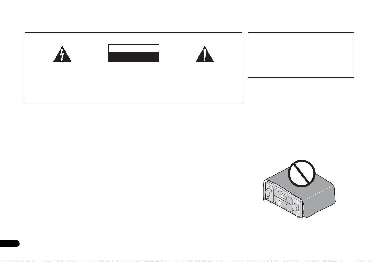
VENTILATION CAUTION
When installing this unit, make sure to leave space
around the unit for ventilation to improve heat radiation
(at least 40 cm at top, 20 cm at rear, and 20 cm at each
side).
WARNING
Slots and openings in the cabinet are provided for
ventilation to ensure reliable operation of the product,
and to protect it from overheating. To prevent fire
hazard, the openings should never be blocked or
covered with items (such as newspapers, table-cloths,
curtains) or by operating the equipment on thick carpet
or a bed.
D3-4-2-1-7b*_A1_En
Operating Environment
Operating environment temperature and humidity:
+5 °C to +35 °C (+41 °F to +95 °F); less than 85 %RH
(cooling vents not blocked)
Do not install this unit in a poorly ventilated area, or in
locations exposed to high humidity or direct sunlight (or
strong artificial light)
D3-4-2-1-7c*_A1_En
VSX-421_SYXCN_QSG_En.book 2 ページ 2011年3月7日 月曜日 午後4時25分
English
Français
Italiano
Nederlands
Español
Deutsch
If the AC plug of this unit does not match the AC
CAUTION
outlet you want to use, the plug must be removed
The STANDBY/ON switch on this unit will not
and appropriate one fitted. Replacement and
completely shut off all power from the AC outlet.
mounting of an AC plug on the power supply cord of
Since the power cord serves as the main disconnect
this unit should be performed only by qualified
device for the unit, you will need to unplug it from the
service personnel. If connected to an AC outlet, the
AC outlet to shut down all power. Therefore, make
cut-off plug can cause severe electrical shock. Make
sure the unit has been installed so that the power
sure it is properly disposed of after removal.
cord can be easily unplugged from the AC outlet in
The equipment should be disconnected by removing
case of an accident. To avoid fire hazard, the power
the mains plug from the wall socket when left unused
cord should also be unplugged from the AC outlet
for a long period of time (for example, when on
when left unused for a long period of time (for
vacation).
example, when on vacation).
D3-4-2-2-1a_A1_En
D3-4-2-2-2a*_A1_En
3
En
This product is for general household purposes. Any
failure due to use for other than household purposes
(such as long-term use for business purposes in a
restaurant or use in a car or ship) and which requires
repair will be charged for even during the warranty
period.
K041_A1_En
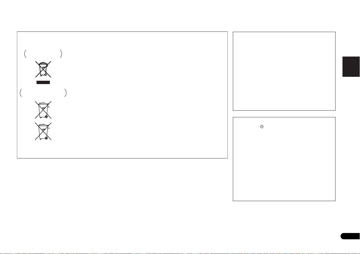
Information for users on collection and disposal of old equipment and used batteries
Symbol for
These symbols on the products, packaging, and/or accompanying documents mean
equipment
that used electrical and electronic products and batteries should not be mixed with
general household waste.
For proper treatment, recovery and recycling of old products and used batteries,
please take them to applicable collection points in accordance with your national
legislation.
By disposing of these products and batteries correctly, you will help to save valuable
Symbol examples
resources and prevent any potential negative effects on human health and the
for batteries
environment which could otherwise arise from inappropriate waste handling.
For more information about collection and recycling of old products and batteries,
please contact your local municipality, your waste disposal service or the point of sale
where you purchased the items.
These symbols are only valid in the European Union.
For countries outside the European Union:
If you wish to discard these items, please contact your local authorities or dealer and
ask for the correct method of disposal.
Pb
K058a_A1_En
WARNING
This equipment is not waterproof. To prevent a fire or
shock hazard, do not place any container filled with
liquid near this equipment (such as a vase or flower
pot) or expose it to dripping, splashing, rain or
moisture.
D3-4-2-1-3_A1_En
WARNING
Before plugging in for the first time, read the following
section carefully.
The voltage of the available power supply differs
according to country or region. Be sure that the
power supply voltage of the area where this unit
will be used meets the required voltage (e.g., 230 V
or 120 V) written on the rear panel.
D3-4-2-1-4*_A1_En
VSX-421_SYXCN_QSG_En.book 3 ページ 2011年3月7日 月曜日 午後4時25分

VSX-421_SYXCN_QSG_En.book 4 ページ 2011年3月7日 月曜日 午後4時25分
Thank you for buying this Pioneer product.
General Disclaimer
Contents
This Quick Start Guide includes instructions for basic
Pioneer Corporation does not guarantee the operation of
connections and operations to allow simple use of the
this CD-ROM with respect to personal computers using
Before you start
. . . . . . . . . . . . . . . . . . . . . . . . . . . .5
receiver. For detailed descriptions of the receiver, see the
any of the applicable OS. In addition, Pioneer
Checking what’s in the box . . . . . . . . . . . . . . . . . . . . . . . 5
“Operating Instructions” provided on the included CD-
Corporation is not liable for any damages incurred as a
Loading the batteries . . . . . . . . . . . . . . . . . . . . . . . . . . . . 5
ROM. The operating instructions can also be
result of use of this CD-ROM and is not responsible for
Flow of settings on the receiver . . . . . . . . . . . . . . . . . . . . 5
downloaded from the Pioneer website (http://
any compensation. The names of private corporations,
www.pioneer.eu).
products and other entities described herein are the
Remote control
. . . . . . . . . . . . . . . . . . . . . . . . . . . . .6
See below for instructions on handling the CD-ROM.
registered trademarks or trademarks of their respective
Connecting your equipment
. . . . . . . . . . . . . . . . . 7
firms.
Operating Environment
Placing the speakers . . . . . . . . . . . . . . . . . . . . . . . . . . . . 7
This CD-ROM can be used with Microsoft® Windows®
* When Using a Mac OS:
Hints on the speaker placement . . . . . . . . . . . . . . . . . . 7
Connecting the speakers . . . . . . . . . . . . . . . . . . . . . . . . . 8
95/98/Me/NT/2000/XP/Vista/7 and Apple Mac OS X 10.4.
Place this CD-ROM in a CD drive and then double-click
Connect the surround back speakers . . . . . . . . . . . . . . 8
Adobe Reader (Version 4.0 or later) is required to read
on the CD-ROM icon to start up the application.
Making cable connections . . . . . . . . . . . . . . . . . . . . . . . . 9
this CD-ROM.
HDMI cables. . . . . . . . . . . . . . . . . . . . . . . . . . . . . . . . . 9
Precautions For Use
About HDMI . . . . . . . . . . . . . . . . . . . . . . . . . . . . . . . . . 9
This CD-ROM is for use with a personal computer. It
Analog audio cables . . . . . . . . . . . . . . . . . . . . . . . . . . 10
cannot be used with a DVD player or music CD player.
Digital audio cables . . . . . . . . . . . . . . . . . . . . . . . . . . 10
Attempting to play this CD-ROM with a DVD player or
Video cables . . . . . . . . . . . . . . . . . . . . . . . . . . . . . . . . 10
music CD player can damage speakers or cause
About video outputs connection . . . . . . . . . . . . . . . . . . 10
Connecting a TV and playback components. . . . . . . . . . 11
impaired hearing due to the large volume.
Connecting using HDMI . . . . . . . . . . . . . . . . . . . . . . . 11
License
Connecting your component with no HDMI terminal
. . 11
Please agree to the “Terms of Use” indicated below
Connecting a satellite receiver or other digital
before using this CD-ROM. Do not use if you are
set-top box . . . . . . . . . . . . . . . . . . . . . . . . . . . . . . . . . . . 12
unwilling to consent to the terms of its use.
Connecting an HDD/DVD recorder, Blu-ray Disc
recorder and other video sources. . . . . . . . . . . . . . . . . . 12
Terms of Use
Connecting other audio components . . . . . . . . . . . . . . . 12
Copyright to data provided on this CD-ROM belongs to
Using the component video jacks . . . . . . . . . . . . . . . . . 13
Pioneer Corporation. Unauthorized transfer, duplication,
Connecting antennas. . . . . . . . . . . . . . . . . . . . . . . . . . . 13
broadcast, public transmission, translation, sales,
Using external antennas . . . . . . . . . . . . . . . . . . . . . . . 14
lending or other such matters that go beyond the scope
Plugging in the receiver . . . . . . . . . . . . . . . . . . . . . . . . . 14
of “personal use” or “citation” as defined by Copyright
Canceling the demo display. . . . . . . . . . . . . . . . . . . . . . 14
Law may be subject to punitive actions. Permission to
use this CD-ROM is granted under license by Pioneer
Basic playback
. . . . . . . . . . . . . . . . . . . . . . . . . . . . .15
Playing a source . . . . . . . . . . . . . . . . . . . . . . . . . . . . . . 15
Corporation.
Listening in surround sound . . . . . . . . . . . . . . . . . . . . . 15
Standard surround sound. . . . . . . . . . . . . . . . . . . . . . 15
Using the Advanced surround effects. . . . . . . . . . . . . 15
Listening to the radio . . . . . . . . . . . . . . . . . . . . . . . . . . . 15
Improving FM sound. . . . . . . . . . . . . . . . . . . . . . . . . . 15
Saving station presets. . . . . . . . . . . . . . . . . . . . . . . . . 15
Listening to station presets. . . . . . . . . . . . . . . . . . . . . 15
4
En
Before you start
5
En
English
Français
Italiano
Nederlands
Español
Deutsch
Before you start
Checking what’s in the box
Please check that you’ve received the following supplied
accessories:
• Remote control
• AAA size IEC R03 dry cell batteries (to confirm system
operation) x2
• AM loop antenna
• FM wire antenna
•Power cord
• Warranty card
• Operating instructions (CD-ROM)
• These quick start guide
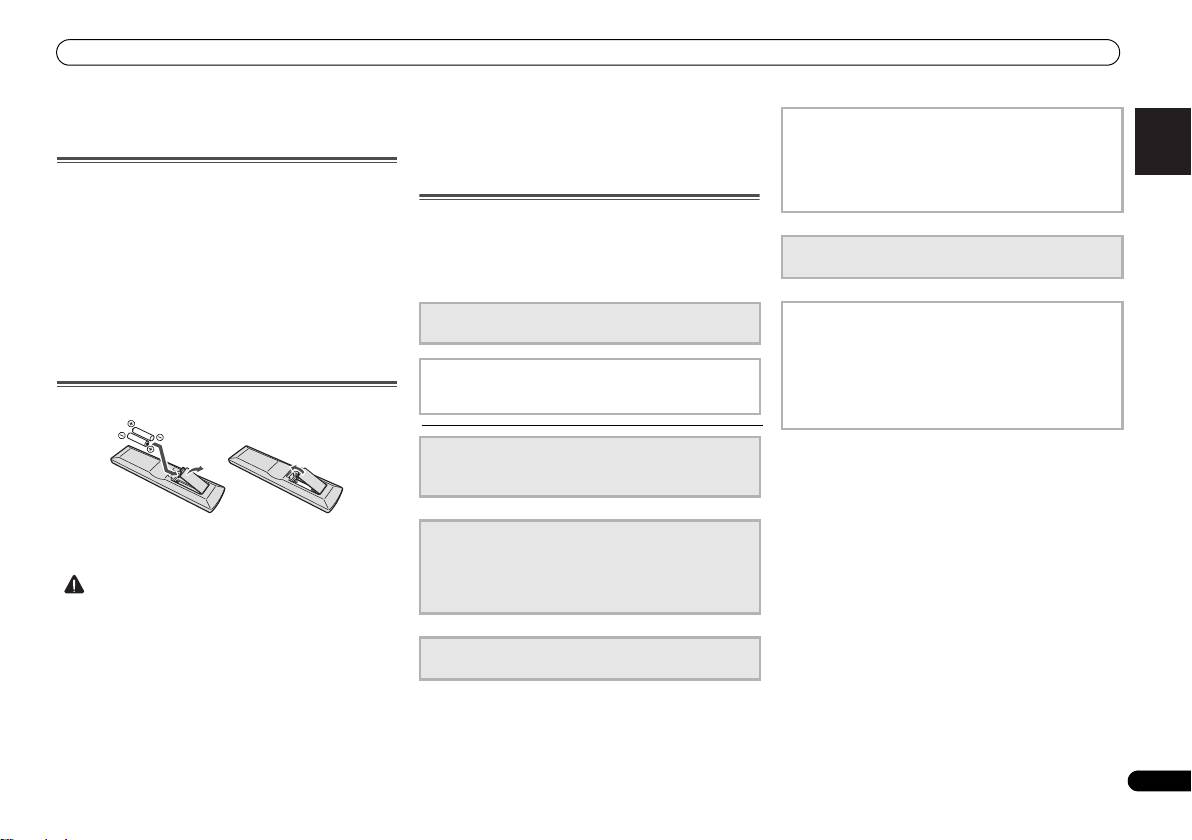
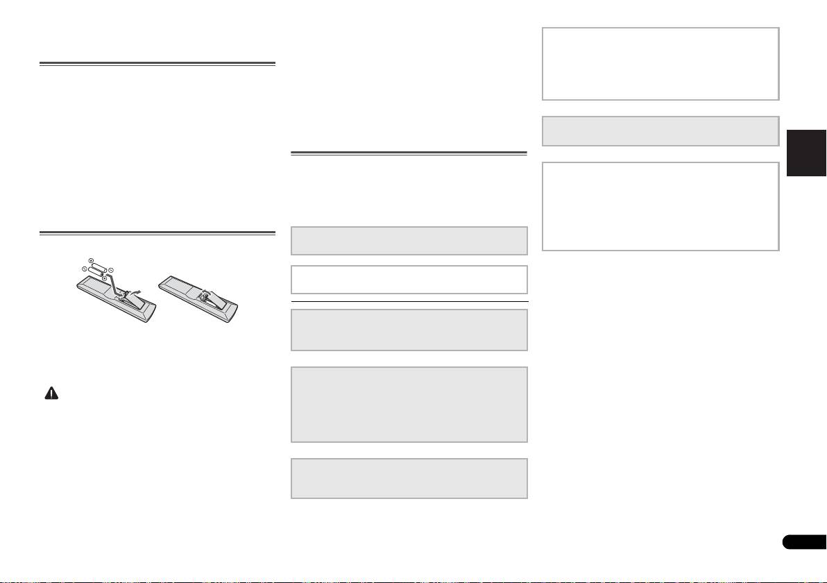
Loading the batteries
The batteries included with the unit are to check initial
operations; they may not last over a long period. We
recommend using alkaline batteries that have a longer life.
CAUTION
VSX-421_SYXCN_QSG_En.book 5 ページ 2011年3月7日 月曜日 午後4時25分
-
Do not use or store batteries in direct sunlight or other
4
The Input Assign menu
excessively hot place, such as inside a car or near a
(When using connections other than the recommended
heater. This can cause batteries to leak, overheat,
connections.)
explode or catch fire. It can also reduce the life or
Using the Audio Return Channel function
performance of batteries.
(When the connected TV supports the HDMI Audio
Return Channel function.)
Flow of settings on the receiver
The unit is a full-fledged AV receiver equipped with an
abundance of functions and terminals. It can be used easily
5
Playing a source (page 15)
after following the procedure below to make the connections
• Listening in surround sound (page 15)
and settings.
The colors of the steps indicate the following:
Required setting item (These items are included in this
6
Adjusting the sound as desired
Quick Start Guide.)
• Using the Sound Retriever
• Better sound using Phase Control
• Using surround back channel processing
Setting to be made as necessary (These items are
• Setting the Up Mix function
explained in the “Operating Instructions” provided on
the included CD-ROM.)
• Setting the Audio options
• The Speaker Setup menu
1
Connecting the speakers
• Placing the speakers (page 7)
• Connecting the speakers (page 8)
2
Connecting the components
• About video outputs connection (page 10)
• Connecting a TV and playback components (page 11)
• Connecting antennas (page 13)
• Plugging in the receiver (page 14)
• Incorrect use of batteries may result in such hazards as
leakage and bursting. Observe the following precautions:
-
Never use new and old batteries together.
3
Power On
-
Insert the plus and minus sides of the batteries properly
• Canceling the demo display (page 14)
according to the marks in the battery case.
-
Batteries with the same shape may have different
voltages. Do not use different batteries together.
-
When disposing of used batteries, please comply with
governmental regulations or environmental public
instruction’s rules that apply in your country or area.
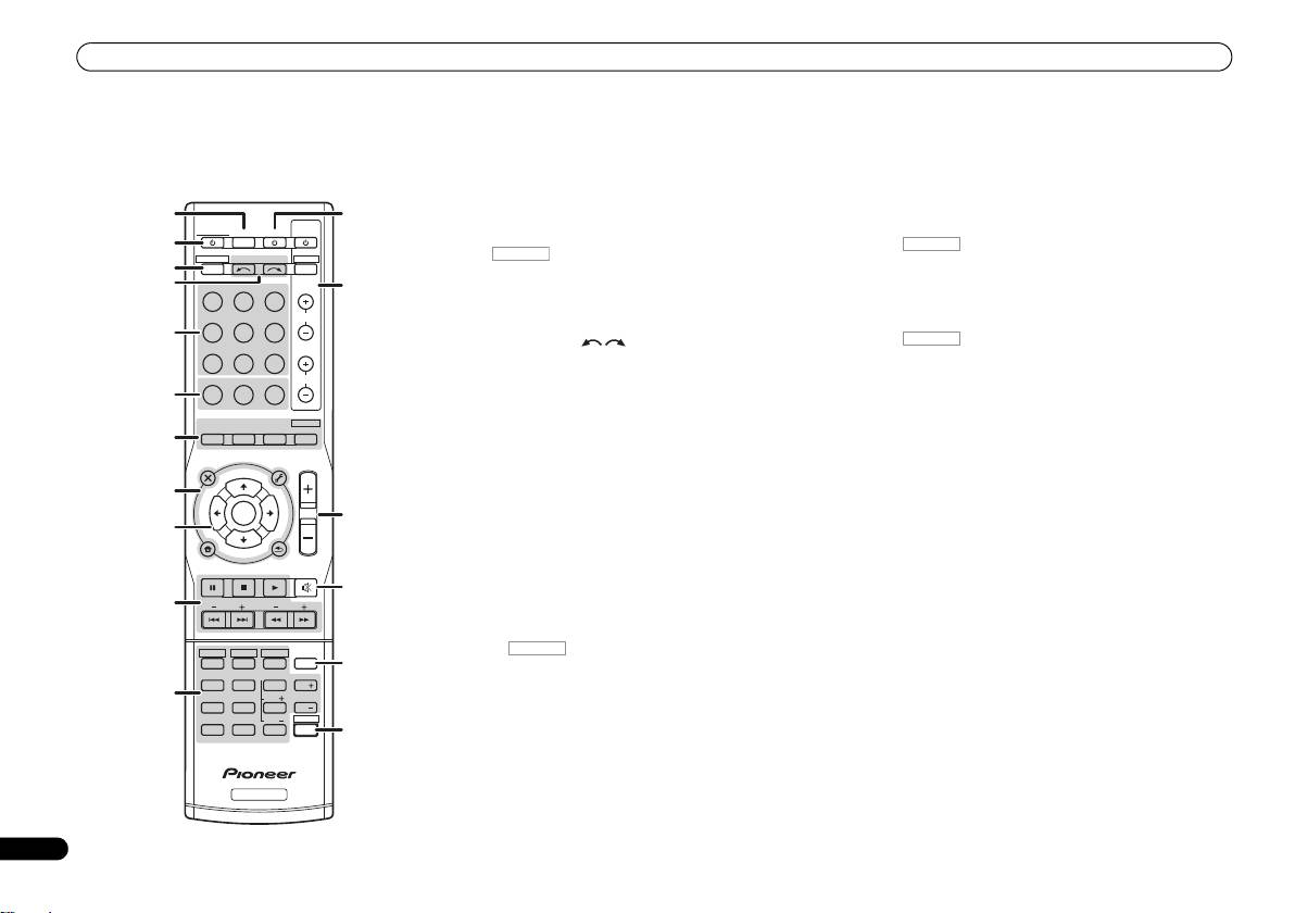
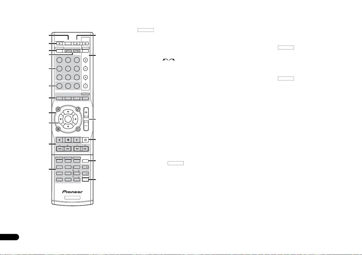
Remote control
1 SLEEP
9
///
(TUNE
/
, PRESET
/
), ENTER
Remote control
Press to change the amount of time before the receiver
Use the arrow buttons when setting up your surround sound
switches into standby (30 min – 60 min – 90 min – Off). You
system.
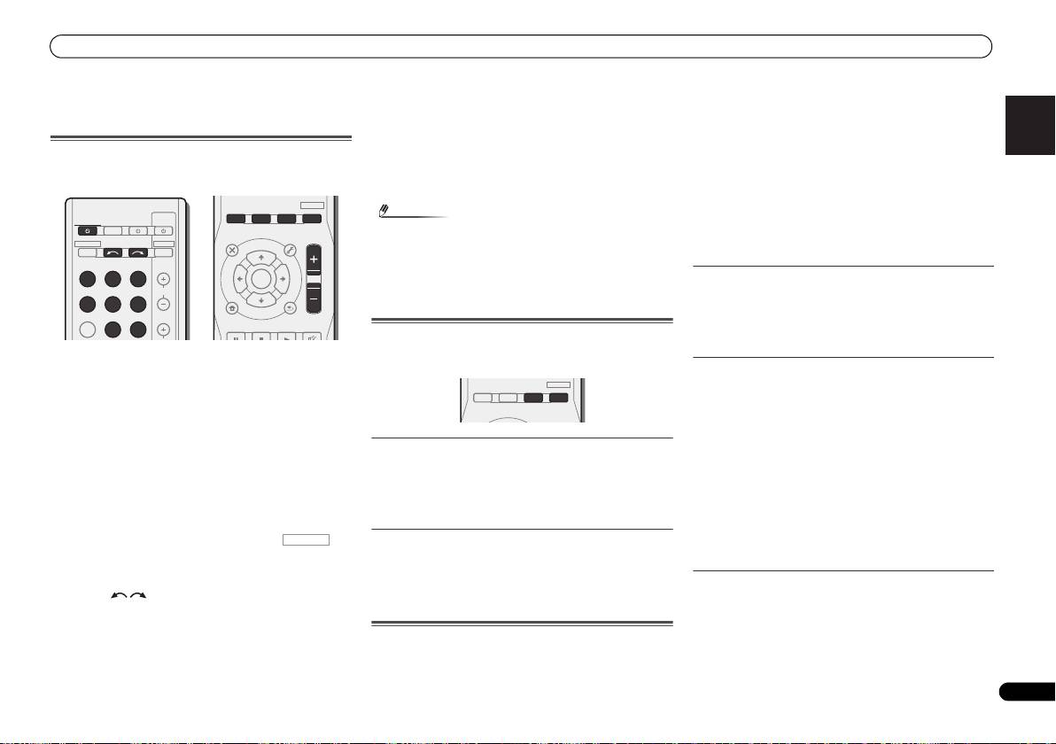
This section explains how to operate the remote control for
can check the remaining sleep time at any time by pressing
Use TUNE / can be used to find radio frequencies and
the receiver.
SLEEP once.
PRESET / can be used to select preset radio stations
(page 15).
1
2
RECEIVER
12
RECEIVER
TV
Switches the receiver between standby and on.
SOURCESLEEP
CONTROL
10 Receiver control buttons
2
Press first to access:
3
RECEIVER DTV/TV
INPUT SELECT
BASS –/+, TRE –/+ – Use to adjust Bass or Treble.
3
INPUT
Switches the remote to control the receiver (used to select
4
BD DVD
TV
13
the white commands above the number buttons
• These controls are disabled when the listening mode is
(MIDNIGHT, etc)). Also use this button to set up surround
set to DIRECT or PURE DIRECT.
DVR/BDR
CD
CD-R
CH
sound or Audio parameters.
11 Receiver control buttons
5
4 INPUT SELECT
Press first to access:
ADAPTER
TUNER
PORTABLE
Use to select the input source (page 15).
SB CH – Press to select ON, AUTO or OFF the surround
back channel.
PHASE
SIGNAL SELS.RETRIEVER
VOL
5 Input function buttons
6
Use to select the input source to this receiver (page 15). This
CH SELECT – Press repeatedly to select a channel, then
will enable you to control other Pioneer components with the
use LEV +/– to adjust the level.
AUTO/
ALC/
BD MENU
DIRECT
STEREO
STANDARD
ADV SURR
remote control.
LEV +/– – Use to adjust the channel level.
7
• ADAPTER button is not used with this receiver.
MIDNIGHT – Switches to Midnight or Loudness listening.
AUDIO
TUNER EDIT
MASTER
PARAMETER
TOOLS
VOLUME
TOP
T
U
N
E
MENU
6 Receiver control buttons
SPEAKERS – Use to change the speaker system on or off.
MENU
8
PHASE – Press to switch on/off Phase Control.
DIMMER – Dims or brightens the display.
T
P
R
S
E
E
ENTER
S
S.RETRIEVER – Press to restore CD quality sound to
P
R
E
T
E
14
12
SOURCE
9
compressed audio sources.
Press to turn on/off other components connected to the
HOME
MENU
T
U
N
E
SIGNAL SEL – Press to select the audio input signal of the
receiver.
BAND
SETUP
RETURN
PTY SEARCH
component to play back.
MUTE
13 TV CONTROL buttons
15
7 Listening mode buttons
These buttons can control only be used with Pioneer TVs.
10
BASS
TRE
Press to select a listening mode (page 15).
14 MASTER VOLUME +/–
8 Receiver setting buttons
Use to set the listening volume.
HDD
DVD
VCR
Press first to access:
15 MUTE
1
2
3
DISP
16
AUDIO PARAMETER – Use to access the Audio options.
Mutes/unmutes the sound.
TEST TONE
SB CH
CH SELECT
4
5
6
CH
11
SETUP – Press to access the System Setup menu.
16 DISP
MIDNIGHT
SPEAKERS
LEV
7
8
9
CH
RETURN – Confirm and exit the current menu screen.
Switches the display of this unit.
DIMMER
LEV
SHIFT
CLR
0
ENTER
17
Press TUNER first to access:
17 SHIFT
+
10
TUNER EDIT – Memorizes stations for recall (page 15).
Press to access the ‘boxed’ commands (above the buttons)
on the remote.
BAND – Switches between AM, FM ST (stereo) and FM
MONO radio bands (page 15).
RECEIVER
PTY SEARCH – Use to search for RDS program types.
6
En
RECEIVER
RECEIVER
VSX-421_SYXCN_QSG_En.book 6 ページ 2011年3月7日 月曜日 午後4時25分
RECEIVER
RECEIVER
Connecting your equipment
7
En
English
Français
Italiano
Nederlands
Español
Deutsch
Connecting your equipment
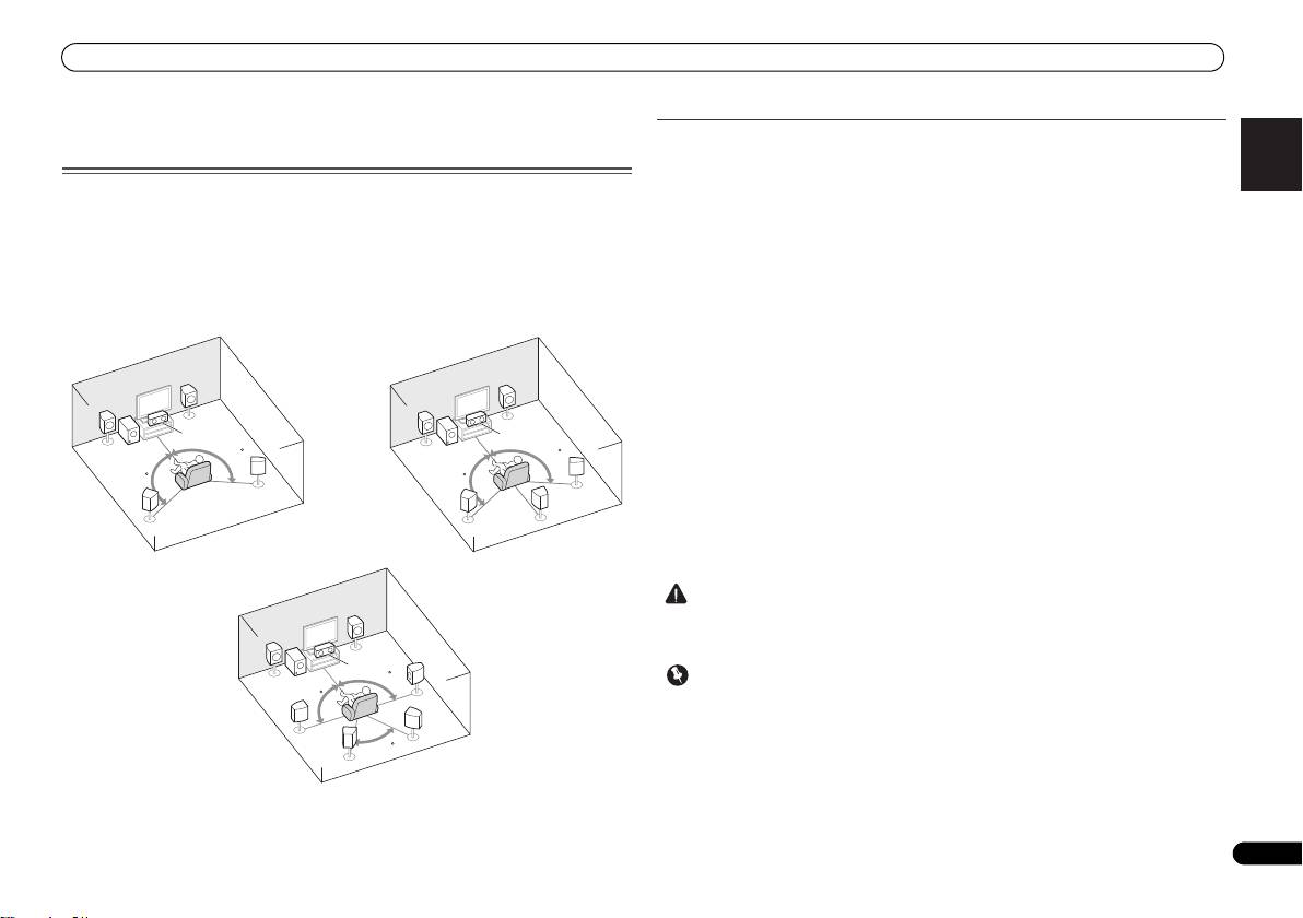
Hints on the speaker placement
Where you put your speakers in the room has a big effect on the quality of the sound. The
following guidelines should help you to get the best sound from your system.
Placing the speakers
• The subwoofer can be placed on the floor. Ideally, the other speakers should be at about
By connecting the left and right front speakers (
L
/
R
), the center speaker (
C
), the left and right
ear-level when you’re listening to them. Putting the speakers on the floor (except the
surround speakers (
SL
/
SR
), and the subwoofer (
SW
), a 5.1 ch surround system can be enjoyed.
subwoofer), or mounting them very high on a wall is not recommended.
Further, by using an external amplifier, you can connect the left and right surround back
• For the best stereo effect, place the front speakers 2 m to 3 m apart, at equal distance from
speakers (SBL/SBR) to boost your system up to a 7.1 ch surround system.
the TV.
• You can also connect one surround back speaker (SB) and enjoy a 6.1 ch surround system.
• If you’re going to place speakers around your CRT TV, use shielded speakers or place the
speakers at a sufficient distance from your CRT TV.
To achieve the best possible surround sound, install your speakers as shown below.
• If you’re using a center speaker, place the front speakers at a wider angle. If not, place
them at a narrower angle.
• Place the center speaker above or below the TV so that the sound of the center channel is
localized at the TV screen. Also, make sure the center speaker does not cross the line
formed by the leading edge of the front left and right speakers.
• It is best to angle the speakers towards the listening position. The angle depends on the
size of the room. Use less of an angle for bigger rooms.
• Surround and surround back speakers should be positioned 60 cm to 90 cm higher than
your ears and titled slight downward. Make sure the speakers don’t face each other. For
DVD-Audio, the speakers should be more directly behind the listener than for home
theater playback.
• If the surround speakers cannot be set directly to the side of the listening position with a
7.1-channel system, the surround effect can be enhanced by turning off the Up Mix
function (see Setting the Up Mix function on Operating Instructions in CD-ROM).
• Try not to place the surround speakers farther away from the listening position than the
front and center speakers. Doing so can weaken the surround sound effect.
a. This layout is available only when the additional amplifier is connected to the unit and the
surround back speakers are connected to the amplifier. For details, see Connect the surround back
speakers on page 8.
CAUTION
• Make sure that all speakers are securely installed. This not only improves sound quality,
but also reduces the risk of damage or injury resulting from speakers being knocked over
or falling in the event of external shocks such as earthquakes.
Important
• To connect the surround back speakers, an additional amplifier is required. Connect the
additional amplifier to the PRE OUT SURR BACK outputs of this unit and connect the
surround back speakers to the additional amplifier (see Connect the surround back
speakers on page 8).
R
R
L
L
C
C
SW
120
SW
120
120
120
SR
SR
SB
SL
SL
R
L
C
SR
90
SW
90
SBR
SL
60
SBL
a
5.1 channel surround system:
6.1 channel surround system:
a
7.1 channel surround system:
VSX-421_SYXCN_QSG_En.book 7 ページ 2011年3月7日 月曜日 午後4時25分
Connecting your equipment
Connecting the speakers
The receiver will work with just two stereo speakers (the front speakers in the diagram) but
using at least three speakers is recommended, and a complete setup is best for surround
sound.
Make sure you connect the speaker on the right to the right (R) terminal and the speaker on
the left to the left (L) terminal. Also make sure the positive and negative (+/–) terminals on the
receiver match those on the speakers.
Be sure to complete all connections before connecting this unit to the AC power source.
Bare wire connections
8
En
CAUTION
Front speaker terminals:
1
Twist exposed wire strands together.
2
Loosen terminal and insert exposed wire.
3
Tighten terminal.
Center and surround speaker terminals:
1
Twist exposed wire strands together.
2
Push open the tabs and insert exposed
wire.
3
Release the tabs.
• These speaker terminals carry HAZARDOUS LIVE voltage. To prevent the risk of electric
shock when connecting or disconnecting the speaker cables, disconnect the power cord
before touching any uninsulated parts.
• Make sure that all the bare speaker wire is twisted together and inserted fully into the
speaker terminal. If any of the bare speaker wire touches the back panel it may cause the
power to cut off as a safety measure.
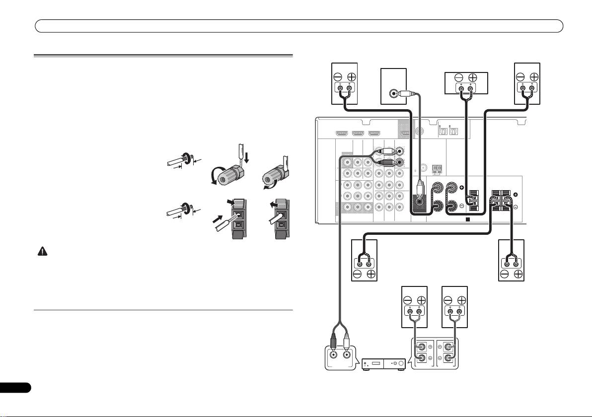
Connect the surround back speakers
Connect the PRE OUT SURR BACK outputs of the unit and additional amplifier to add a
surround back speaker.
• You can use the additional amplifier on the surround back channel pre-outs for a single
speaker as well. In this case plug the amplifier into the left (L (Single)) terminal only.
12 3
10 mm
12 3
10 mm
HDMI
DVR/BDR IN
DVD IN
BD IN
OUT
COAXIAL
IN
IN
OPTICAL
IN
1
1
2
ASSIGNABLE
ASSIGNABLE
(
CD
)
(
TV/SAT
)
(
CD-R/TAPE
)
VIDEO
AUDIO
DVR/BDR
CD-R/TAPE
SURR BACK
L
MONITOR
TV/SAT
BD
(
Single
)
OUT
IN
IN
OUT
PRE OUT
R
ANTENNA
FM
DVR/
CD
UNBAL
BDR
75
L
AM LOOP
OUT
IN
DVD IN
IN IN
FRONT
RL
IN
1
(
DVD
)
R
CENTER
SURROUND
RL
ASSIGNABLE
IN
2
L
(
DVR/
BDR
)
IN
IN
R
MONITOR
SUBWOOFER
OUT
YP
B PR
TV/SAT
BD
DVD
COMPONENT
VIDEO
PRE OUT
SPEAKERS
A
LINE LEVEL
INPUT
RL
ANALOG
AUDIO IN
SPEAKER R SPEAKER L
Front right
Front left
Subwoofer
Center
Surround right
Surround left
Surround back
Surround back
right
left
Surround back channel amplifier
VSX-421_SYXCN_QSG_En.book 8 ページ 2011年3月7日 月曜日 午後4時25分
Connecting your equipment
9
En
English
Français
Italiano
Nederlands
Español
Deutsch
Making cable connections
Make sure not to bend the cables over the top of this unit (as
shown in the illustration). If this happens, the magnetic field
produced by the transformers in this unit may cause a
humming noise from the speakers.
Important
• Before making or changing connections, switch off the
power and disconnect the power cord from the AC outlet.
• Before unplugging the power cord, switch the power into
standby.
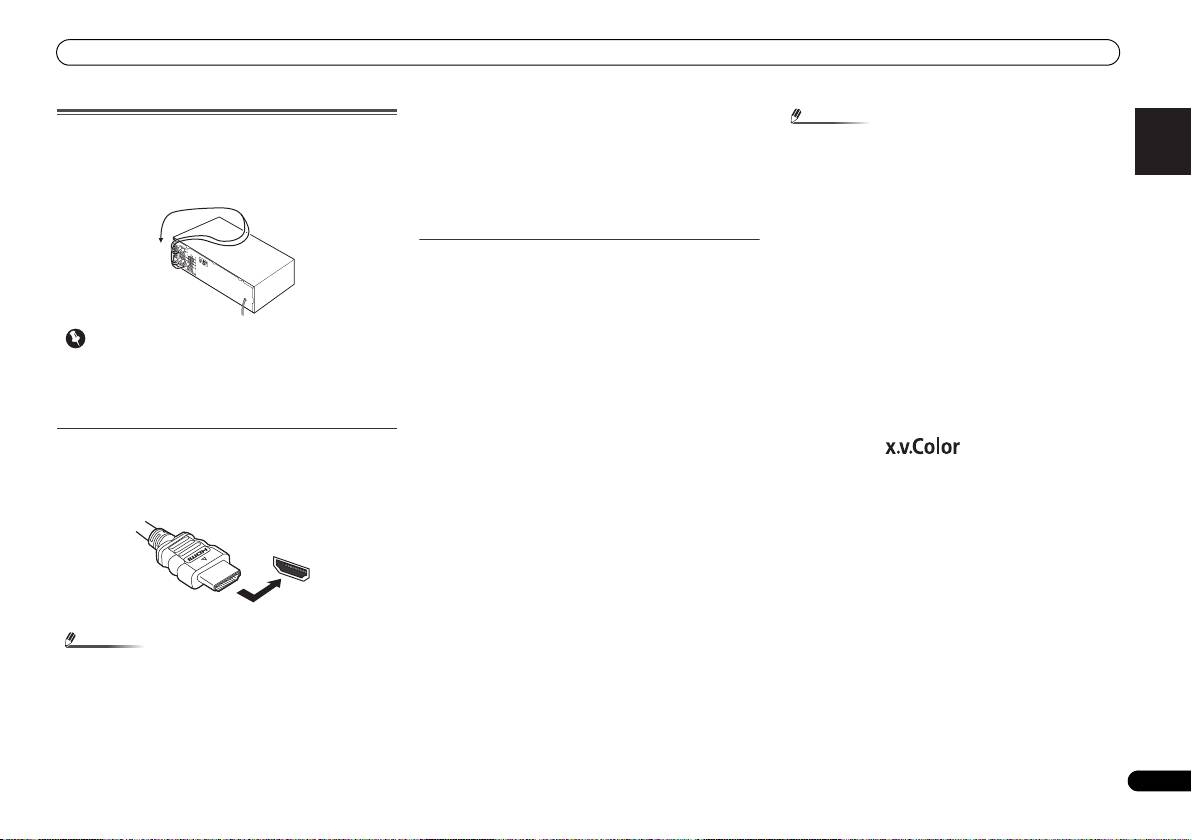
HDMI cables
Both video and sound signals can be transmitted
simultaneously with one cable. If connecting the player and
the TV via this receiver, for both connections, use HDMI
cables.
Be careful to connect the terminal in the proper direction.
Note
• If the video signal does not appear on your TV, try
adjusting the resolution settings on your component or
display. Note that some components (such as video game
units) have resolutions that may not be displayed. In this
case, use a (analog) composite connection.
• When the video signal from the HDMI is 480i, 480p, 576i
or 576p, Multi Ch PCM sound and HD sound cannot be
received.
About HDMI
The HDMI connection transfers uncompressed digital video,
as well as almost every kind of digital audio that the
connected component is compatible with, including DVD-
Video, DVD-Audio, SACD, Dolby Digital Plus, Dolby TrueHD,
DTS-HD Master Audio (see below for limitations), Video CD/
Super VCD and CD.
This receiver incorporates High-Definition Multimedia
®
Interface (HDMI
) technology.
This receiver supports the functions described below through
HDMI connections.
• Digital transfer of uncompressed video (contents
protected by HDCP (1080p/24, 1080p/60, etc.))
• 3D signal transfer
• Deep Color signal transfer
• x.v.Color signal transfer
• Audio Return Channel
• Input of multi-channel linear PCM digital audio signals
(192 kHz or less) for up to 8 channels
• Input of the following digital audio formats:
– Dolby Digital, Dolby Digital Plus, DTS, High bitrate
audio (Dolby TrueHD, DTS-HD Master Audio), DVD-
Audio, CD, SACD (DSD 2 ch only), Video CD, Super VCD
• Synchronized operation with components using the
Control with HDMI function (see Control with HDMI
function on Operating Instructions in CD-ROM)
• Set the HDMI parameter to THRU (THROUGH) and set
the input signal to HDMI, if you want to hear HDMI audio
output from your TV (no sound will be heard from this
receiver) (see Setting the Audio options and Selecting the
audio input signal on Operating Instructions in CD-ROM).
Note
VSX-421_SYXCN_QSG_En.book 9 ページ 2011年3月7日 月曜日 午後4時25分
®
• Use a High Speed HDMI
cable. If HDMI cable other than
®
a High Speed HDMI
cable is used, it may not work
properly.
• When an HDMI cable with a built-in equalizer is
connected, it may not operate properly.
• 3D, Deep Color, x.v.Color signal transfer and Audio
Return Channel are only possible when connected to a
compatible component.
• HDMI format digital audio transmissions require a longer
time to be recognized. Due to this, interruption in the
audio may occur when switching between audio formats
or beginning playback.
• Turning on/off the device connected to this unit’s HDMI
OUT terminal during playback, or disconnecting/
connecting the HDMI cable during playback, may cause
noise or interrupted audio.
HDMI, the HDMI Logo and High-Definition Multimedia
Interface are trademarks or registered trademarks of HDMI
Licensing, LLC in the United States and other countries.
“x.v.Color” and are trademarks of Sony
Corporation.
HDMI
Connecting your equipment
Analog audio cables
Use stereo RCA phono cables to connect analog audio
components. These cables are typically red and white, and
you should connect the red plugs to R (right) terminals and
white plugs to L (left) terminals.
Digital audio cables
Commercially available coaxial digital audio cables or optical
cables should be used to connect digital components to this
receiver.
10
En
Note
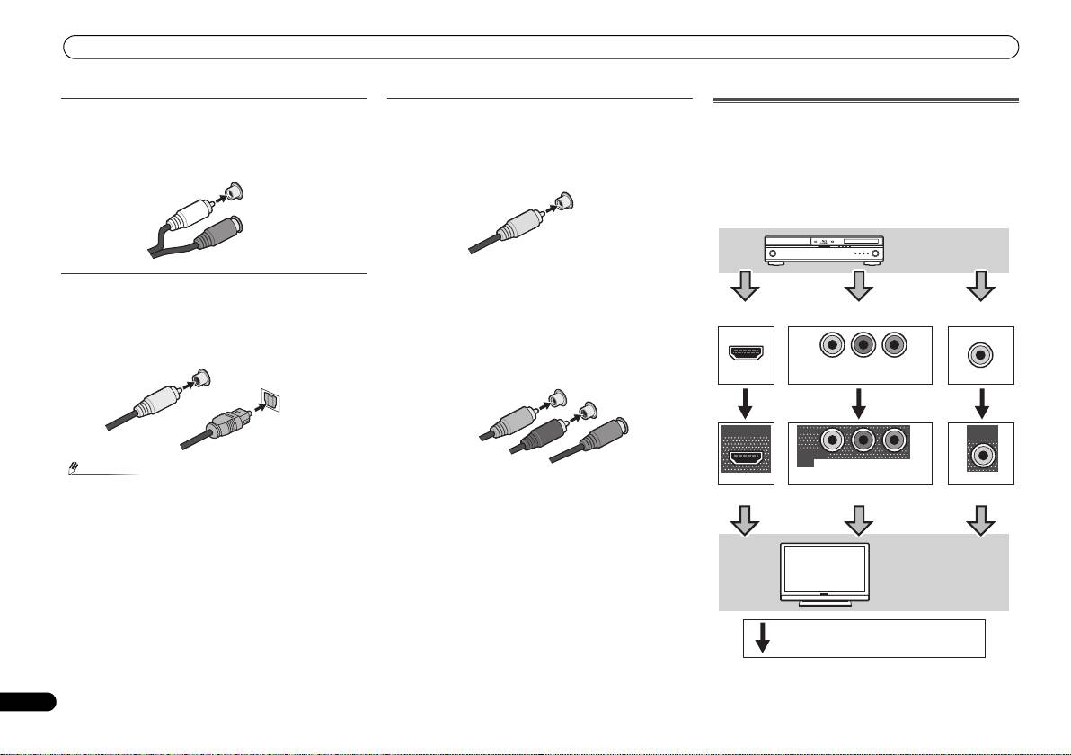
Video cables
About video outputs connection
This receiver is not loaded with a video converter. When you
Standard RCA video cables
use component video cables or HDMI cables for connecting
These cables are the most common type of video connection
to the input device, the same cables should be used for
and are used to connect to the composite video terminals.
connecting to the TV.
The yellow plugs distinguish them from cables for audio.
The signals input from the analog (composite and
L
component) video inputs of this unit will not be output from
AUDIO
the HDMI OUT.
R
Component video cables
Use component video cables to get the best possible color
reproduction of your video source. The color signal of the TV
is divided into the luminance (Y) signal and the color (P
B and
P
R) signals and then output. In this way, interference between
the signals is avoided.
• When connecting optical cables, be careful when
inserting the plug not to damage the shutter protecting
the optical socket.
• When storing optical cable, coil loosely. The cable may be
damaged if bent around sharp corners.
• You can also use a standard RCA video cable for coaxial
digital connections.
White (Left)
Red (Right)
COAXIAL
IN
OPTICAL
IN
Coaxial digital
audio cable
Optical cable
VIDEO
Yellow
COMPONENT VIDEO
Y
P
B
P
R
Green (Y)
Blue (PB)
Red (PR)
IN
IN
IN
YP
B
P
R
HDMI
COMPONENT VIDEO
VIDEO
OUT
MONITOR
OUT
MONITOR
OUT
YP
B
P
R
HDMI
COMPONENT VIDEO
VIDEO
Playback
component
Terminal for connection with source device
Terminal for connection with TV monitor
TV
Video signals can be output.
VSX-421_SYXCN_QSG_En.book 10 ページ 2011年3月7日 月曜日 午後4時25分
Connecting your equipment
11
En
English
Français
Italiano
Nederlands
Español
Deutsch
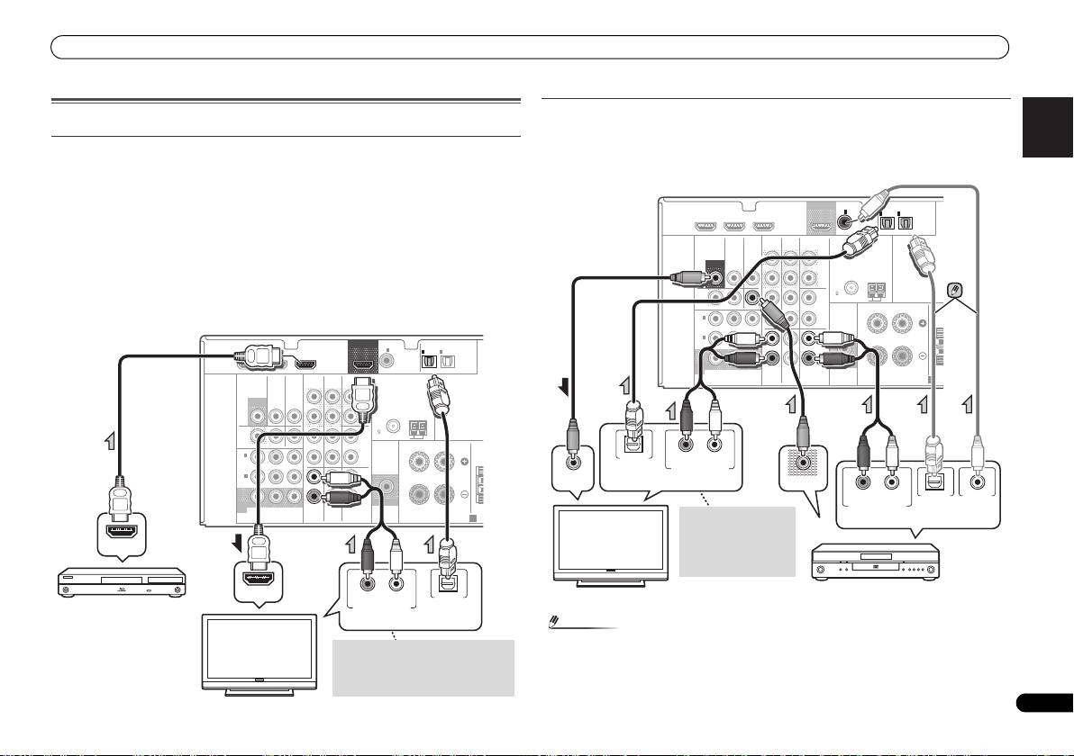
Connecting your component with no HDMI terminal
Connecting a TV and playback components
This diagram shows connections of a TV and DVD player (or other playback component) with
no HDMI terminal to the receiver.
Connecting using HDMI
• If both TV and player has a component video jacks, you can connect these too. See Using
If you have an HDMI or DVI (with HDCP) equipped component (Blu-ray Disc player, etc.), you
the component video jacks on page 13 for more on this.
can connect it to this receiver using a commercially available HDMI cable.
If the TV and playback components support the Control with HDMI feature, the convenient
Control with HDMI functions can be used (see Control with HDMI function on Operating
Instructions in CD-ROM).
• The following connection/setting is required to listen to the sound of the TV over this receiver.
-
If the TV does not support the HDMI Audio Return Channel function, connect the receiver
and TV with audio cables (as shown).
-
If the TV supports the HDMI Audio Return Channel function, the sound of the TV is input
to the receiver via the HDMI terminal, so there is no need to connect an audio cable. In
this case, set ARC at HDMI SET to ON (see HDMI Setup on Operating Instructions in CD-
ROM).
Note
• In order to listen to the audio from the DVD player that is connected to this receiver using
an optical cable or a coaxial cable, first, switch to the DVD input, then press SIGNAL SEL
to choose the audio signal O2 (OPTICAL2) or C1 (COAXIAL1).
VIDEO
MONITOR
OUT
HDMI
DVR/BDR IN
DVD IN
BD IN
OUT
COAXIAL
IN
1
IN
IN
OPTICAL
1
2
ASSIGNABLE
ASSIGNABLE
(
CD
)
(
TV/SAT
)
(
CD-R/TAPE
)
VIDEO
AUDIO
DVR/BDR
CD-R/TAPE
SURR BACK
L
MONITOR
TV/SAT
BD
(
Single
)
OUT
IN
IN
OUT
PRE OUT
R
ANTENNA
FM
DVR /
CD
UNBAL
BDR
75
L
AM LOOP
OUT
IN
DVD IN
IN IN
RL
FRONT
IN
1
R
CEN
(
DVD
)
ASSIGNABLE
IN
2
L
(
DVR /
BDR
)
IN
IN
R
MONITOR
SUBWOOFER
OUT
YP
B
P
R
TV/SAT
BD
DVD
COMPONENT
VIDEO
PRE OUT
SPEAKERS
A
HDMI OUT
HDMI IN
RL
OPTICAL
DIGITAL AUDIO OUTANALOG AUDIO OUT
HDMI/DVI-compatible
Blu-ray Disc player
Select one
If the TV does not support the HDMI
Audio Return Channel function, this
HDMI/DVI-
connection is required to listen to the
compatible TV
TV sound over the receiver.
HDMI
DVR/BDR IN
DVD IN
BD IN
OUT
COAXIAL
IN
1
IN
IN
OPTICAL
1
2
ASSIGNABLE
ASSIGNABLE
(
CD
)
(
TV/SAT
)
(
CD-R/TAPE
)
VIDEO
AUDIO
DVR/BDR
CD-R/TAPE
SURR BACK
L
MONITOR
TV/SAT
BD
(
Single
)
OUT
IN
IN
OUT
PRE OUT
R
ANTENNA
FM
DVR /
CD
UNBAL
BDR
75
L
AM LOOP
OUT
IN
DVD IN
IN IN
RL
FRONT
IN
1
R
CEN
(
DVD
)
ASSIGNABLE
IN
2
L
(
DVR /
BDR
)
IN
IN
R
MONITOR
SUBWOOFER
OUT
YP
B
P
R
TV/SAT
BD
DVD
COMPONENT
VIDEO
PRE OUT
SPEAKERS
A
T
OPTICAL
RL
DIGITAL AUDIO OUT ANALOG AUDIO OUT
VIDEO IN
VIDEO OUT
RL
OPTICAL COAXIAL
DIGITAL AUDIO OUTANALOG AUDIO OUT
Select one
This connection is
Select one
required in order to
listen to the sound of
the TV over the
receiver.
TV
DVD player
VSX-421_SYXCN_QSG_En.book 11 ページ 2011年3月7日 月曜日 午後4時25分
Connecting your equipment
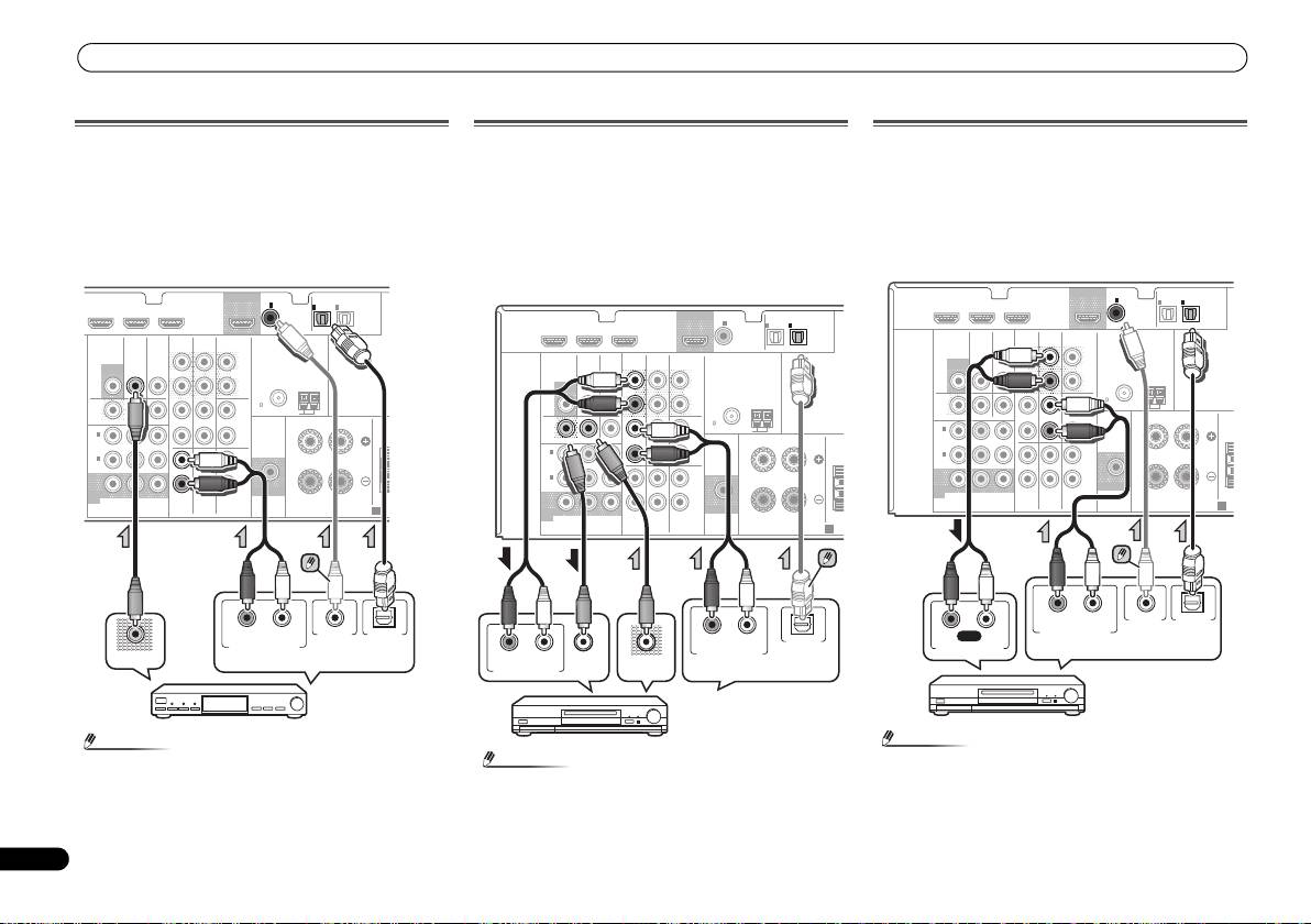
Connecting a satellite receiver or other digital
set-top box
Satellite and cable receivers, and terrestrial digital TV tuners
are all examples of so-called ‘set-top boxes’.
• If the set-top box or video component also has an HDMI
or a component video output, you can connect this too.
See Connecting using HDMI on page 11 or Using the
component video jacks on page 13 for more on this.
12
En
Note
Connecting an HDD/DVD recorder, Blu-ray Disc
recorder and other video sources
This receiver has audio/video inputs and outputs suitable for
connecting analog or digital video recorders, including HDD/
DVD recorders and Blu-ray Disc recorders.
• Only the signals that are input to the VIDEO IN terminal
can be output from the VIDEO OUT terminal.
• Audio signals that are input through the digital terminal
will not be output from the analog terminal.
• In order to listen to the audio from the source component
that is connected to this receiver using a coaxial cable,
first, switch to the TV/SAT, then press SIGNAL SEL to
choose the audio signal C1 (COAXIAL1).
Note
Connecting other audio components
The number and kind of connections depends on the kind of
component you’re connecting. Follow the steps below to
connect a CD-R, MD, DAT, tape recorder or other audio
component.
• Note that you must connect digital components to analog
audio jacks if you want to record to/from digital
components (like an MD) to/from analog components.
• In order to listen to the audio from the source component
that is connected to this receiver using an optical cable,
first, switch to the DVR/BDR input, then press SIGNAL
SEL to choose the audio signal O2 (OPTICAL2).
Note
DVR/BDR IN
DVD IN
BD IN
OUT
COAXIAL
IN
1
IN
IN
OPTICAL
1
2
ASSIGNABLE
ASSIGNABLE
(
CD
)
(
TV/SAT
)
(
CD-R/TAPE
)
VIDEO
AUDIO
DVR/ BDR
CD-R/TAPE
SURR BACK
L
MONITOR
TV/SAT
BD
(
Single
)
OUT
IN
IN
OUT
PRE OUT
R
ANTENNA
FM
DVR /
CD
UNBAL
BDR
75
L
AM LOOP
OUT
IN
DVD IN
IN IN
RL
FRONT
IN
1
R
CEN
(
DVD
)
ASSIGNABLE
IN
2
L
(
DVR /
BDR
)
IN
IN
R
MONITOR
SUBWOOFER
OUT
YP
B
P
R
TV/SAT
BD
DVD
COMPONENT
VIDEO
PRE OUT
SPEAKERS
A
• In order to listen to the audio from the CD player that is
connected to this receiver using a coaxial cable, first,
switch to the CD-R input, then press SIGNAL SEL to
choose the audio signal C1 (COAXIAL1).
T
RL
OPTICALCOAXIAL
DIGITAL AUDIO OUTANALOG AUDIO OUT
VIDEO OUT
Select one
Set-top box, etc.
HDMI
DVR/BDR IN
DVD IN
BD IN
OUT
COAXIAL
IN
1
IN
IN
OPTICAL
1
2
ASSIGNABLE
ASSIGNABLE
(
CD
)
(
TV/SAT
)
(
CD-R/TAPE
)
VIDEO
AUDIO
DVR/BDR
CD-R/TAPE
SURR BACK
L
MONITOR
TV/SAT
BD
(
Single
)
OUT
IN
IN
OUT
PRE OUT
R
ANTENNA
FM
DVR /
CD
UNBAL
BDR
75
L
AM LOOP
OUT
IN
DVD IN
IN IN
RL
FRONT
IN
1
R
CEN
(
DVD
)
ASSIGNABLE
IN
2
L
(
DVR /
BDR
)
IN
IN
R
MONITOR
SUBWOOFER
OUT
YP
B
P
R
TV/SAT
BD
DVD
COMPONENT
VIDEO
PRE OUT
SPEAKERS
A
T
RL
OPTICAL
RL
ANALOG AUDIO OUT
DIGITAL AUDIO OUT
ANALOG AUDIO IN
VIDEO IN
VIDEO OUT
Select one
HDD/DVD recorder, Blu-ray
Disc recorder, etc.
HDMI
DVR/BDR IN
DVD IN
BD IN
OUT
COAXIAL
IN
1
IN
IN
OPTICAL
1
2
ASSIGNABLE
ASSIGNABLE
(
CD
)
(
TV/SAT
)
(
CD-R/TAPE
)
VIDEO
AUDIO
DVR/BDR
CD-R/TAPE
SURR BACK
L
MONITOR
TV/SAT
BD
(
Single
)
OUT
IN
IN
OUT
PRE OUT
R
ANTENNA
FM
DVR /
CD
UNBAL
BDR
75
L
AM LOOP
OUT
IN
DVD IN
IN IN
RL
FRONT
IN
1
R
CE
(
DVD
)
ASSIGNABLE
IN
2
L
(
DVR /
BDR
)
IN
IN
R
MONITOR
SUBWOOFER
OUT
YP
B
P
R
TV/SAT
BD
DVD
COMPONENT
VIDEO
PRE OUT
SPEAKERS
A
N
RL
OPTICALCOAXIAL
RL
REC
DIGITAL AUDIO OUTANALOG AUDIO OUT
ANALOG AUDIO IN
Select one
CD-R, MD, DAT,
Tape recorder, etc.
VSX-421_SYXCN_QSG_En.book 12 ページ 2011年3月7日 月曜日 午後4時25分
Connecting your equipment
13
En
English
Français
Italiano
Nederlands
Español
Deutsch
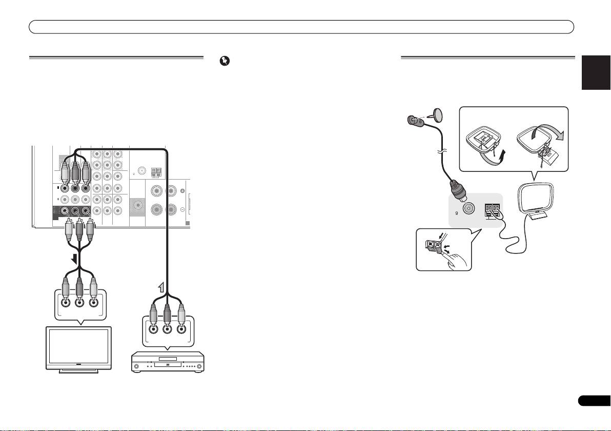
Using the component video jacks
Component video should deliver superior picture quality
when compared to composite video. A further advantage (if
your source and TV are both compatible) is progressive-scan
video, which delivers a very stable, flicker-free picture. See
the manuals that came with your TV and source component
to check whether they are compatible with progressive-scan
video.
• For the audio connection, refer to Connecting your
component with no HDMI terminal on page 11.
Important
Connecting antennas
• If you connect any source component to the receiver
Connect the AM loop antenna and the FM wire antenna as
using a component video input, you must also have your
shown below. To improve reception and sound quality,
TV connected to this receiver’s COMPONENT VIDEO
connect external antennas (see Using external antennas
MONITOR OUT jacks.
below).
• If necessary, assign the component video inputs to the
input source you’ve connected. This only needs to be
done if you didn’t connect according to the following
defaults:
-
COMPONENT VIDEO IN 1: DVD
DVR
-
COMPONENT VIDEO IN 2: DVR/BDR
See The Input Assign menu on Operating Instructions in
CD-ROM for more on this.
ANTENNA
DVR /
BDR
L
R
ASSIGNABLE
L
R
YP
B
P
R
COMPONENT
VIDEO
PRE OUT
SPEAKERS
A
1
Push open the tabs, then insert one wire fully into each
terminal, then release the tabs to secure the AM antenna
wires.
2
Fix the AM loop antenna to the attached stand.
To fix the stand to the antenna, bend in the direction
indicated by the arrow (fig. a) then clip the loop onto the
stand (fig. b).
3
Place the AM antenna on a flat surface and in a direction
giving the best reception.
4
Connect the FM wire antenna into the FM antenna
socket.
For best results, extend the FM antenna fully and fix to a wall
or door frame. Don’t drape loosely or leave coiled up.
/
BDR
OUT
C
D-R
/
TAPE
SURR BACK
L
MONITOR
TV/SAT
BD
(
Single
)
OUT
IN
IN
PRE OUT
R
FM
CD
UNBAL
75
AM LOOP
OUT
IN
DVD IN
IN IN
RL
FRONT
IN
1
C
(
DVD
)
IN
2
(
DVR /
BDR
)
IN
IN
MONITOR
SUBWOOFER
OUT
TV/SAT
BD
DVD
PR
P
B
Y
COMPONENT VIDEO IN
PR
P
B
Y
COMPONENT VIDEO OUT
TV
DVD player
2
4
ANTENNA
FM
UNBAL
75
AM LOOP
3
1
fig. a
fig. b
VSX-421_SYXCN_QSG_En.book 13 ページ 2011年3月7日 月曜日 午後4時25分
Connecting your equipment
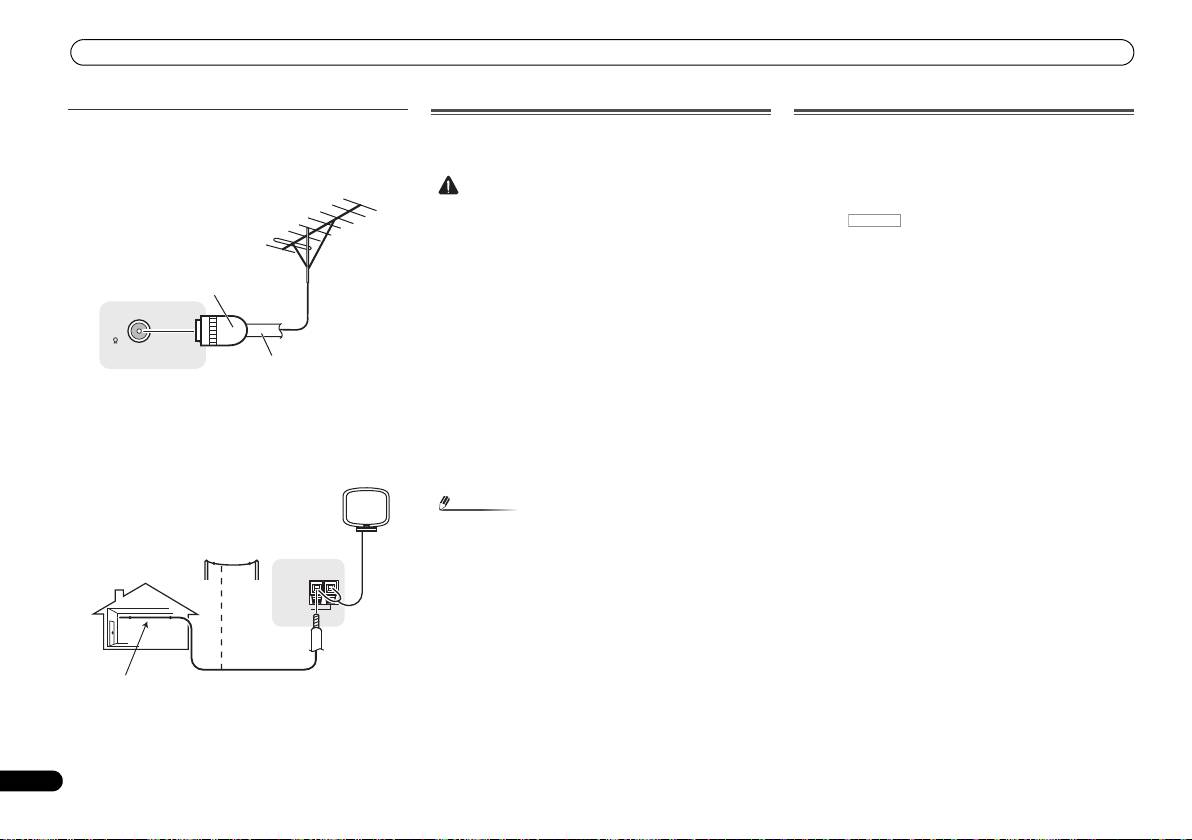
Using external antennas
Plugging in the receiver
Only plug in after you have connected all your components to
To improve FM reception
this receiver, including the speakers.
Use a PAL connector (not supplied) to connect an external
FM antenna.
To improve AM reception
Connect a 5 m to 6 m length of vinyl-coated wire to the AM
antenna terminal without disconnecting the supplied AM
loop antenna.
For the best possible reception, suspend horizontally
outdoors.
14
En
CAUTION
• Handle the power cord by the plug part. Do not pull out
the plug by tugging the cord, and never touch the power
cord when your hands are wet, as this could cause a short
circuit or electric shock. Do not place the unit, a piece of
furniture, or other object on the power cord or pinch the
cord in any other way. Never make a knot in the cord or tie
it with other cables. The power cords should be routed so
that they are not likely to be stepped on. A damaged
power cord can cause a fire or give you an electric shock.
Check the power cord once in a while. If you find it
damaged, ask your nearest Pioneer authorized
independent service company for a replacement.
• Do not use any power cord other than the one supplied
with this unit.
• Do not use the supplied power cord for any purpose other
than that described below.
• The receiver should be disconnected by removing the
mains plug from the wall socket when not in regular use,
e.g., when on vacation.
Note
Canceling the demo display
The display on the front panel shows various information
(demo displays) when the receiver is not operating.
You can turn off the demo display.
1
Press
RECEIVER
to switch the receiver on.
2
Press , then press SETUP.
3
Use
/
to select ‘FL DEMO’ from the System Setup
menu, then press ENTER.
4
Use
/
to choose OFF for the demo display.
5
When you’re finished, press RETURN.
ANTENNA
•Press SETUP to exit the System Setup menu.
FM
UNBAL
75
• After this receiver is connected to an AC outlet, a 2
second to 10 second HDMI initialization process begins.
You cannot carry out any operations during this process.
The HDMI indicator in the front panel display blinks
during this process, and you can turn on this receiver
once it has stopped blinking. When you set the Control
with HDMI to OFF, you can skip this process. For details
about the Control with HDMI feature, see Control with
HDMI function on Operating Instructions in CD-ROM.
1
Plug the supplied power cord into the AC IN socket on
the back of the receiver.
2
Plug the other end into a power outlet.
One-touch
PAL connector
75 Ω coaxial cable
ANTENNA
AM LOOP
Outdoor
antenna
Indoor antenna
5 m to 6 m
(vinyl-coated wire)
RECEIVER
VSX-421_SYXCN_QSG_En.book 14 ページ 2011年3月7日 月曜日 午後4時25分
Basic playback
15
En
English
Français
Italiano
Nederlands
Español
Deutsch
4
Press AUTO/DIRECT to select ‘AUTO SURROUND’ and
Basic playback
start playback of the source.
If you’re playing a Dolby Digital or DTS surround sound DVD
disc, with a digital audio connection, you should hear
Playing a source
surround sound. If you’re playing a stereo source or if the
Here are the basic instructions for playing a source (such as
connection is an analog audio connection, you will only hear
a DVD disc) with your home theater system.
sound from the front left/right speakers in the default
listening mode.
1
Switch on your system components and receiver.
Start by switching on the playback component (for example a
DVD player), your TV and subwoofer (if you have one), then
the receiver (press RECEIVER).
2
Switch the TV input to the input that connects this
receiver.
For example, if you connected this receiver to the VIDEO
jacks on your TV, make sure that the VIDEO input is now
selected.
3
Press input function buttons to select the input function
you want to play.
• The input of the receiver will switch over, and you will be
able to operate other components using the remote
control. To operate the receiver, first press on
the remote control, then press the appropriate button to
operate.
• The input source can also be selected by using INPUT
SELECT buttons on the remote control, or by
using the front panel INPUT SELECTOR dial. In this case,
the remote control won’t switch operational modes.
If you selected the proper input source and there is still no
sound, press SIGNAL SEL to select the audio input signal for
playback.
Note
3
Tune to a station.
There are three ways to do this:
Automatic tuning
Press and hold TUNE / for about a second. The
receiver will start searching for the next station.
Manual tuning
To change the frequency one step at a time, press
AUTO/
ALC/
BD MENU
TUNE /.
DIRECT
STEREO
STANDARD
ADV SURR
RECEIVER
TV
SOURCESLEEP
CONTROL
High speed tuning
• You may need to check the digital audio output settings
AUDIO
TUNER EDIT
MASTER
PARAMETER
TOOLS
VOLUME
Press and hold TUNE / for high speed tuning.
RECEIVER
INPUT SELECT
DTV/TV
MENU
on your DVD player or digital satellite receiver. It should
TOP
T
U
N
E
INPUT
Release the button at the frequency you want.
MENU
be set to output Dolby Digital, DTS and 88.2 kHz/96 kHz
BD DVD TV
E
T
P
R
PCM (2 channel) audio, and if there is an MPEG audio
S
E
E
ENTER
S
R
E
option, set this to convert the MPEG audio to PCM.
Improving FM sound
P
T
DVR/BDR
CD
CD-R
CH
If the TUNE or ST indicators don’t light when tuning to an FM
5
Use MASTER VOLUME to adjust the volume level.
HOME
MENU
T
U
N
E
station because the signal is weak, set the receiver to the
BAND
ADAPTER
TUNER
PORTABLE
SETUP
RETURN
PTY SEARCH
mono reception mode.
MUTE
Listening in surround sound
Press BAND to select FM MONO.
Using this receiver, you can listen to any source in surround
sound.
Saving station presets
If you often listen to a particular radio station, it’s convenient
to have the receiver store the frequency for easy recall
whenever you want to listen to that station.
1
Tune to a station you want to memorize.
See Listening to the radio above for more on this.
Standard surround sound
2
Press TUNER EDIT.
This receiver provide basic surround sound for stereo and
The display shows PRESET, then a blinking MEM and station
multichannel sources.
preset.
While listening to a source, press ALC/STANDARD
3
Press PRESET
/
to select the station preset you want.
repeatedly to select a listening mode.
4
Press ENTER.
Using the Advanced surround effects
The preset number stop blinking and the receiver stores the
station.
The Advanced surround effects can be used for a variety of
additional surround sound effects.
Listening to station presets
While listening to a source, press ADV SURR repeatedly
You will need to have some presets stored to do this. See
to select a listening mode.
Saving station presets above if you haven’t done this already.
Press PRESET
/
to select the station preset you want.
Listening to the radio
1
Press TUNER to select the tuner.
© 2011 PIONEER CORPORATION.
All rights reserved.
2
Use BAND to change the band (FM or AM), if necessary.
RECEIVER
AUTO/
ALC/
BD MENU
DIRECT
STEREO
STANDARD
ADV SURR
AUDIO
TUNER EDIT
MASTER
PARAMETER
TOOLS
VOLUME
VSX-421_SYXCN_QSG_En.book 15 ページ 2011年3月7日 月曜日 午後4時25分
VSX-421_SYXCN_QSG_Fr.book 2 ページ 2011年3月7日 月曜日 午前10時51分
Ce produit est destiné à une utilisation domestique
IMPORTANT
générale. Toute panne due à une utilisation autre qu'à
des fins privées (comme une utilisation à des fins
ATTENTION
commerciales dans un restaurant, dans un autocar
DANGER D´ELECTROCUTION
NE PAS OUVRIR
ou sur un bateau) et qui nécessite une réparation
sera aux frais du client, même pendant la période de
Ce symbole de l’éclair, placé dans un
ATTENTION :
Ce point d’exclamation, placé dans un
garantie.
triangle équilatéral, a pour but d’attirer
POUR ÉVITER TOUT RISQUE
triangle équilatéral, a pour but d’attirer
K041_A1_Fr
l’attention de l’utilisateur sur la présence, à
D’ÉLECTROCUTION, NE PAS ENLEVER LE
l’attention de l’utilisateur sur la présence,
l’intérieur du coffret de l’appareil, de
COUVERCLE (NI LE PANNEAU ARRIÈRE).
dans les documents qui accompagnent
“tensions dangereuses” non isolées d’une
AUCUNE PIÈCE RÉPARABLE PAR
l’appareil, d’explications importantes du
grandeur suffisante pour représenter un
L’UTILISATEUR NE SE TROUVE À
point de vue de l’exploitation ou de
PRÉCAUTION DE VENTILATION
risque d’électrocution pour les êtres
L’INTÉRIEUR. CONFIER TOUT ENTRETIEN À
l’entretien.
Lors de l’installation de l’appareil, veillez à laisser un
humains.
UN PERSONNEL QUALIFIÉ UNIQUEMENT.
espace suffisant autour de ses parois de manière à
D3-4-2-1-1_A1_Fr
améliorer la dissipation de chaleur (au moins 40 cm sur
le dessus, 20 cm à l’arrière et 20 cm de chaque côté).
AVERTISSEMENT
AVERTISSEMENT
AVERTISSEMENT
Cet appareil n’est pas étanche. Pour éviter les risques
Pour éviter les risques d’incendie, ne placez aucune
Les fentes et ouvertures du coffret sont prévues pour la
d’incendie et de décharge électrique, ne placez près de
flamme nue (telle qu’une bougie allumée) sur
ventilation, pour assurer un fonctionnement stable de
lui un récipient rempli d’eau, tel qu’un vase ou un pot
l’appareil.
l’appareil et pour éviter sa surchauffe. Pour éviter les
de fleurs, et ne l’exposez pas à des gouttes d’eau, des
D3-4-2-1-7a_A1_Fr
risques d’incendie, ne bouchez jamais les ouvertures et
éclaboussures, de la pluie ou de l’humidité.
ne les recouvrez pas d’objets, tels que journaux, nappes
D3-4-2-1-3_A1_Fr
Milieu de fonctionnement
ou rideaux, et n’utilisez pas l’appareil posé sur un tapis
Température et humidité du milieu de fonctionnement :
épais ou un lit.
AVERTISSEMENT
De +5 °C à +35 °C (de +41 °F à +95 °F) ; Humidité
D3-4-2-1-7b*_A1_Fr
Avant de brancher l’appareil pour la première, lisez
relative inférieure à 85 % (orifices de ventilation non
attentivement la section suivante.
obstrués)
La tension de l’alimentation électrique disponible
N’installez pas l’appareil dans un endroit mal ventilé ou
varie selon le pays ou la région. Assurez-vous que
un lieu soumis à une forte humidité ou en plein soleil
la tension du secteur de la région où l’appareil sera
(ou à une forte lumière artificielle).
utilisé correspond à la tension requise (par ex. 230
D3-4-2-1-7c*_A1_Fr
V ou 120 V), indiquée sur le panneau arrière.
D3-4-2-1-4*_A1_Fr
2
Fr
English
Français
Italiano
Nederlands
Español
Deutsch
3
Fr
Information à destination des utilisateurs sur la collecte et l’élimination des
Si la fiche d’alimentation secteur de cet appareil ne
convient pas à la prise secteur à utiliser, la fiche doit
équipements et batteries usagés
être remplacée par une appropriée. Ce
Ces symboles qui figurent sur les produits, les emballages et/ou les documents
Marquage pour les
remplacement et la fixation d’une fiche secteur sur le
d’accompagnement signifient que les équipements électriques et électroniques et
équipements
cordon d’alimentation de cet appareil doivent être
batteries usagés ne doivent pas être jetés avec les déchets ménagers et font l’objet
effectués par un personnel de service qualifié. En cas
d’une collecte sélective.
de branchement sur une prise secteur, la fiche de
Pour assurer l’enlèvement et le traitement appropriés des produits et batteries
coupure peut provoquer une sérieuse décharge
usagés, merci de les retourner dans les points de collecte sélective habilités
électrique. Assurez-vous qu’elle est éliminée
conformément à la législation locale en vigueur.
correctement après sa dépose.
L’appareil doit être déconnecté en débranchant sa
Exemples de marquage
En respectant les circuits de collecte sélective mis en place pour ces produits, vous
fiche secteur au niveau de la prise murale si vous
pour les batteries
contribuerez à économiser des ressources précieuses et à prévenir les impacts
prévoyez une période prolongée de non utilisation
négatifs éventuels sur la santé humaine et l’environnement qui pourraient résulter
(par exemple avant un départ en vacances).
d’une mauvaise gestion des déchets.
D3-4-2-2-1a_A1_Fr
Pour plus d’information sur la collecte et le traitement des produits et batteries
usagés, veuillez contacter votre municipalité, votre service de gestion des déchets
ou le point de vente chez qui vous avez acheté ces produits.
ATTENTION
L’interrupteur STANDBY/ON de cet appareil ne
Ces symboles ne sont valables que dans les pays de l’Union Européenne.
coupe pas complètement celui-ci de sa prise secteur.
Pour les pays n’appartenant pas à l’Union Européenne :
Comme le cordon d’alimentation fait office de
Si vous souhaitez jeter ces articles, veuillez contacter les autorités ou revendeurs
Pb
dispositif de déconnexion du secteur, il devra être
locaux pour connaître les méthodes d’élimination appropriées.
débranché au niveau de la prise secteur pour que
l’appareil soit complètement hors tension. Par
K058a_A1_Fr
conséquent, veillez à installer l’appareil de telle
manière que son cordon d’alimentation puisse être
facilement débranché de la prise secteur en cas
d’accident. Pour éviter tout risque d’incendie, le
cordon d’alimentation sera débranché au niveau de
la prise secteur si vous prévoyez une période
prolongée de non utilisation (par exemple avant un
départ en vacances).
D3-4-2-2-2a*_A1_Fr
VSX-421_SYXCN_QSG_Fr.book 3 ページ 2011年3月7日 月曜日 午前10時51分

VSX-421_SYXCN_QSG_Fr.book 4 ページ 2011年3月7日 月曜日 午前10時51分
Merci pour l’achat de ce produit Pioneer.
Avis de non-responsabilité
Table des matières
Ce guide rapide contient les instructions relatives aux
Pioneer Corporation ne garantit pas le fonctionnement
raccordements et opérations de base permettant une
de ce CD-ROM pour les ordinateurs personnels utilisant
Préparatifs
. . . . . . . . . . . . . . . . . . . . . . . . . . . . . . . . . 5
utilisation simple de ce récepteur. Pour des descriptions
n’importe lequel des systèmes d’exploitation
Vérification des accessoires livrés avec l’appareil . . . . . . 5
plus détaillées du récepteur, référez-vous au “Mode
applicables. De plus, Pioneer Corporation ne peut être
Mise en place des piles . . . . . . . . . . . . . . . . . . . . . . . . . . 5
d’emploi” sur le CD-ROM fourni. Le mode d’emploi peut
tenu responsable pour tout dommages subis à la suite
Organigramme des réglages sur le récepteur . . . . . . . . . 5
aussi être téléchargé du site Pioneer (http://
de l’utilisation de ce CD-ROM, n’est tenu à aucune
www.pioneer.eu).
compensation. Les nom des sociétés privées, des
Télécommande
. . . . . . . . . . . . . . . . . . . . . . . . . . . . .6
Voir ci-dessous pour l’emploi du CD-ROM.
produits ou d’autres entités citées ici sont des marques
Raccordement de votre équipement
. . . . . . . . . . 7
déposées ou des marque de commerce de leur
Environnement d’exploitation
Installation des enceintes . . . . . . . . . . . . . . . . . . . . . . . . 7
entreprise respective.
Ce CD-ROM peut être utilisé avec Microsoft®
Conseils d’installation des enceintes . . . . . . . . . . . . . . 7
Raccordement des enceintes. . . . . . . . . . . . . . . . . . . . . . 8
Windows® 95/98/Me/NT/2000/XP/Vista/7 et Apple Mac
* Lors de l’utilisation de Mac OS :
Raccordez les enceintes surround arrière. . . . . . . . . . . 8
OS X 10.4.
Placez ce CD-ROM dans un lecteur de CD et
Raccordements des câbles . . . . . . . . . . . . . . . . . . . . . . . 9
Adobe Reader (Version 4.0 ou supérieur) est requis pour
doublecliquez sur l’icône du CD-ROM pour démarrer
Câbles HDMI . . . . . . . . . . . . . . . . . . . . . . . . . . . . . . . . 9
lire ce CD-ROM.
l’application.
À propos de HDMI . . . . . . . . . . . . . . . . . . . . . . . . . . . . 9
Précautions d’utilisation
Câbles audio analogiques. . . . . . . . . . . . . . . . . . . . . . 10
Ce CD-ROM est conçu pour être utilisé avec un
Câbles audio numériques . . . . . . . . . . . . . . . . . . . . . . 10
ordinateur personnel. Il ne peut pas être utilisé avec un
Câbles vidéo . . . . . . . . . . . . . . . . . . . . . . . . . . . . . . . . 10
lecteur de DVD ni un lecteur de CD audio. Essayer de lire
À propos du raccordement des sorties vidéo . . . . . . . . . 10
Raccordement d’un téléviseur et de périphériques de
ce CD-ROM avec un lecteur de DVD ou un lecteur de CD
lecture . . . . . . . . . . . . . . . . . . . . . . . . . . . . . . . . . . . . . . 11
audio peut endommager les enceintes ou causer une
Connexion au moyen de l’interface HDMI. . . . . . . . . . 11
altération auditive à cause du volume sonore élevé qui
Raccordement d’un équipement dépourvu de borne
pourrait être produit.
HDMI . . . . . . . . . . . . . . . . . . . . . . . . . . . . . . . . . . . . . 11
Licence
Raccordement d’un récepteur satellite ou d’un boîtier
Veuillez accepter les “Conditions d’utilisation” indiquées
décodeur numérique . . . . . . . . . . . . . . . . . . . . . . . . . . . 12
ci-dessous avant d’utiliser ce CD-ROM. Ne l’utilisez pas
Raccordement d’un enregistreur HDD/DVD, d’un
si vous ne souhaitez pas accepter les conditions
enregistreur Blu-ray Disc et d’autres sources vidéo . . . . 12
d’utilisation.
Raccordement d’autres appareils audio. . . . . . . . . . . . . 12
Utilisation des prises femelles vidéo en
Conditions d’utilisation
composantes . . . . . . . . . . . . . . . . . . . . . . . . . . . . . . . . . 13
Les droits d’auteur des données de ce CD-ROM
Raccordement des antennes . . . . . . . . . . . . . . . . . . . . . 13
appartiennent à Pioneer Corporation. Un transfert, une
Utilisation des antennes externes . . . . . . . . . . . . . . . . 14
copie, une diffusion, une transmission publique, une
Branchement du récepteur . . . . . . . . . . . . . . . . . . . . . . 14
traduction, une vente, un prêt ou toute autre action non
Désactivation du mode d’affichage de
autorisée qui sort des limites de l’“utilisation
démonstration . . . . . . . . . . . . . . . . . . . . . . . . . . . . . . . . 14
personnelle” ou d’une “citation”, comme défini par les
Lecture de base
. . . . . . . . . . . . . . . . . . . . . . . . . . . .15
lois sur les droits d’auteur, peut être soumise à des
Lecture d’une source . . . . . . . . . . . . . . . . . . . . . . . . . . . 15
actions pénales. L’autorisation d’utiliser ce CD-ROM est
Les modes d’écoute de votre système . . . . . . . . . . . . . . 15
donnée sous licence de Pioneer Corporation.
Son surround standard. . . . . . . . . . . . . . . . . . . . . . . . 15
Utilisation des effets surround avancés . . . . . . . . . . . 15
Pour écouter la radio . . . . . . . . . . . . . . . . . . . . . . . . . . . 15
Amélioration du son FM . . . . . . . . . . . . . . . . . . . . . . . 15
Mémorisation de stations préréglées . . . . . . . . . . . . . 15
Pour écouter les stations préréglées. . . . . . . . . . . . . . 15
4
Fr
5
Fr
English
Français
Italiano
Nederlands
Español
Deutsch
Préparatifs
Vérification des accessoires livrés avec
l’appareil
Veuillez vérifier que les accessoires suivants sont livrés avec
l’appareil :
• Télécommande
• Piles à anode sèche AAA IEC R03 (pour vérifier le bon
fonctionnement du système) x 2
• Antenne cadre AM
• Antenne filaire FM
• Cordon d’alimentation
• Carte de garantie
• Mode d’emploi (CD-ROM)
•Le présent Guide de démarrage
Mise en place des piles
Les piles de la télécommande fournies avec l’appareil
permettent d’effectuer les premières opérations ; il est
possible qu’elles ne durent pas très longtemps. Nous
recommandons l’usage de piles alcalines, dont la durée de
vie est supérieure.
ATTENTION
VSX-421_SYXCN_QSG_Fr.book 5 ページ 2011年3月7日 月曜日 午前10時51分
-
Au moment d’éliminer les piles usagées, veuillez
4
Menu d’affectation d’entrée
respecter les réglementations gouvernementales ou les
(Si vous voulez effectuer d’autres liaisons que celles
recommandations publiques relatives à la protection de
recommandées.)
l’environnement en vigueur dans votre pays ou région.
Utilisation de la fonction Audio Return Channel
-
N’utilisez ni ne conservez les piles sous la lumière
(Lorsque le téléviseur connecté prend en charge la
directe du soleil ou dans un endroit excessivement
fonction HDMI Audio Return Channel.)
chaud, comme une voiture ou à proximité d’un appareil
de chauffage. Les piles risqueraient de fuir, de
surchauffer, d’exploser ou de s’enflammer. Ceci
pourrait aussi réduire la durée de vie et les
5
Lecture d’une source (page 15)
performances des piles.
• Les modes d’écoute de votre système (page 15)
Organigramme des réglages sur le récepteur
6
Réglage des préférences de son
Cet appareil est un récepteur AV à part entière présentant un
• Utilisation de la fonction Sound Retriever
grand nombre de fonctions et de prises. Il peut être utilisé
• Un meilleur son grâce à la fonction Phase Control
facilement lorsque les raccordements et les réglages
• Utilisation du traitement de canal surround arrière
mentionnés ci-dessous ont été effectués.
• Réglage de la fonction Up Mix
Les couleurs des étapes ont la signification suivante :
• Réglage des options audio
Élément nécessitant un réglage (Ces éléments sont traités
• Le menu Speaker Setup
dans le présent Guide de démarrage).
Réglage à effectuer si nécessaire (Ces éléments sont
traités dans le Mode d’emploi inclus dans le CD-ROM).
1
Raccordement des enceintes
• Installation des enceintes (page 7)
• Raccordement des enceintes (page 8)
2
Raccordement des composants
•À propos du raccordement des sorties vidéo (page 10)
• Raccordement d’un téléviseur et de périphériques de
• Une mauvaise utilisation des piles peut provoquer des
lecture (page 11)
accidents tels que fuites ou explosions. Veuillez observer
• Raccordement des antennes (page 13)
les recommandations suivantes :
• Branchement du récepteur (page 14)
-
N’utilisez jamais des piles neuves et usagées dans le
même appareil.
-
Insérez les piles en respectant les indications de
3
Mise sous tension
polarité situées à l’intérieur du boîtier.
• Désactivation du mode d’affichage de démonstration
-
Des piles de même forme peuvent avoir des voltages
(page 14)
différents. N’utilisez jamais des piles de voltage différent
dans le même appareil.
2
RECEIVER
9
///
(TUNE
/
, PRESET
/
), ENTER
Télécommande
Cette touche permet d’allumer le récepteur et de le mettre en
Utilisez les touches fléchées pour régler votre système de son
veille.
surround.
Cette section explique l’utilisation de la télécommande de
l’appareil.
Les touches TUNE / permettent de rechercher une
3
fréquence radio et les touches PRESET / servent à
1
12
Pour attribuer la télécommande au contrôle du récepteur
rechercher une station de radio préréglée (page 15).
RECEIVER
TV
SOURCESLEEP
CONTROL
(permet de sélectionner les commandes blanches au-dessus
2
des touches numérotées (MIDNIGHT, etc.)). Utilisez
10 Touches de commande du récepteur
RECEIVER DTV/TV
INPUT SELECT
également cette touche pour configurer le son surround ou
Appuyez d’abord sur pour accéder au menu :
3
INPUT
les paramètres audio.
BASS –/+, TRE –/+ – Pour ajuster les fréquences graves
4
BD DVD
TV
13
et les fréquences aiguës.
4 INPUT SELECT
DVR/BDR
CD
CD-R
CH
Servent à sélectionner la source d’entrée (page 15).
• Ces commandes sont désactivées lorsque le mode
5
d’écoute est réglé sur DIRECT ou sur PURE DIRECT.
5 Touches de fonction d’entrée
ADAPTER
TUNER
PORTABLE
Pour sélectionner la source d’entrée de ce récepteur
11 Touches de commande du récepteur
(page 15). Ceci permet de commander d’autres équipements
Appuyez d’abord sur pour accéder au menu :
PHASE
SIGNAL SELS.RETRIEVER
VOL
Pioneer avec la télécommande.
SB CH – Appuyez sur cette touche pour sélectionner le
6
• La touche ADAPTER n’est pas utilisée sur cet appareil.
mode ON, AUTO, ou OFF pour le canal surround arrière.
AUTO/
ALC/
BD MENU
DIRECT
STEREO
STANDARD
CH SELECT – Appuyez sur cette touche plusieurs fois
ADV SURR
6 Touches de commande du récepteur
7
pour sélectionner un canal, puis sur LEV +/– pour régler
PHASE – Permet d’activer/de désactiver la correction de
AUDIO
TUNER EDIT
MASTER
le niveau sur.
PARAMETER
TOOLS
VOLUME
phase.
TOP
N
E
MENU
T
U
MENU
LEV +/– – Ces touches permettent d’ajuster le niveau des
S.RETRIEVER – Appuyez sur cette touche pour restaurer
8
canaux.
T
P
un son de qualité CD vers des sources audio
E
S
E
R
E
ENTER
S
R
T
E
14
MIDNIGHT – Permet de sélectionner le mode d’écoute
P
compressées.
9
Midnight ou Loudness.
SIGNAL SEL – Appuyez pour sélectionner le signal audio
HOME
MENU
T
U
N
E
BAND
d’entrée de l’équipement à partir duquel vous souhaitez
SPEAKERS – Utilisez cette touche pour utiliser ou non le
SETUP
RETURN
PTY SEARCH
MUTE
effectuer la lecture.
système d’enceintes.
15
DIMMER – Obscurcit ou éclaircit l’affichage.
7 Touches de mode d’écoute
10
BASS
TRE
Utilisez ces touches pour sélectionner un mode d’écoute
12
SOURCE
(page 15).
Cette touche permet de mettre sous/hors tension d’autres
composants connectés au récepteur.
HDD
DVD
VCR
8 Touches de réglage du récepteur
1
2
3
DISP
16
13 Touches TV CONTROL
TEST TONE
SB CH
CH SELECT
Appuyez d’abord sur pour accéder au menu :
4
5
6
CH
Ces touches de commande peuvent être utilisées
11
AUDIO PARAMETER – Permet d’accéder aux options
MIDNIGHT
SPEAKERS
LEV
uniquement avec les téléviseurs Pioneer.
7
8
9
CH
Audio.
DIMMER
LEV
SHIFT
14 MASTER VOLUME +/–
CLR
0
ENTER
17
SETUP – Appuyez pour accéder au menu de
+
10
Permet de régler le volume d’écoute.
configuration du système.
RETURN – Permet de confirmer et de quitter l’écran du
15 MUTE
menu affiché.
Permet de couper/restaurer le son.
RECEIVER
Appuyez d’abord sur TUNER pour accéder au menu :
16 DISP
TUNER EDIT – Permet de mémoriser des stations de
Permet de sélectionner l’écran de cet appareil.
radio à rappeler (page 15).
17 SHIFT
1 SLEEP
BAND – Permet de naviguer entre les bandes de signaux
Appuyez sur cette touche pour accéder aux commandes
Appuyez sur cette touche pour modifier le délai qui s’écoule
avant que le récepteur ne passe en mode veille (30 min –
radio AM, FM ST (stéréo) et FM MONO (page 15).
‘encadrées’ (situées au-dessus des touches) de la
télécommande.
60 min – 90 min – Off). Vous pouvez vérifier le temps restant
PTY SEARCH – Permet de rechercher des programmes
avant le passage en mode veille en appuyant une fois sur la
de type RDS.
touche SLEEP.
6
Fr
RECEIVER
RECEIVER
RECEIVER
RECEIVER
VSX-421_SYXCN_QSG_Fr.book 6 ページ 2011年3月7日 月曜日 午前10時51分
