Pioneer DEH-80PRS: instruction
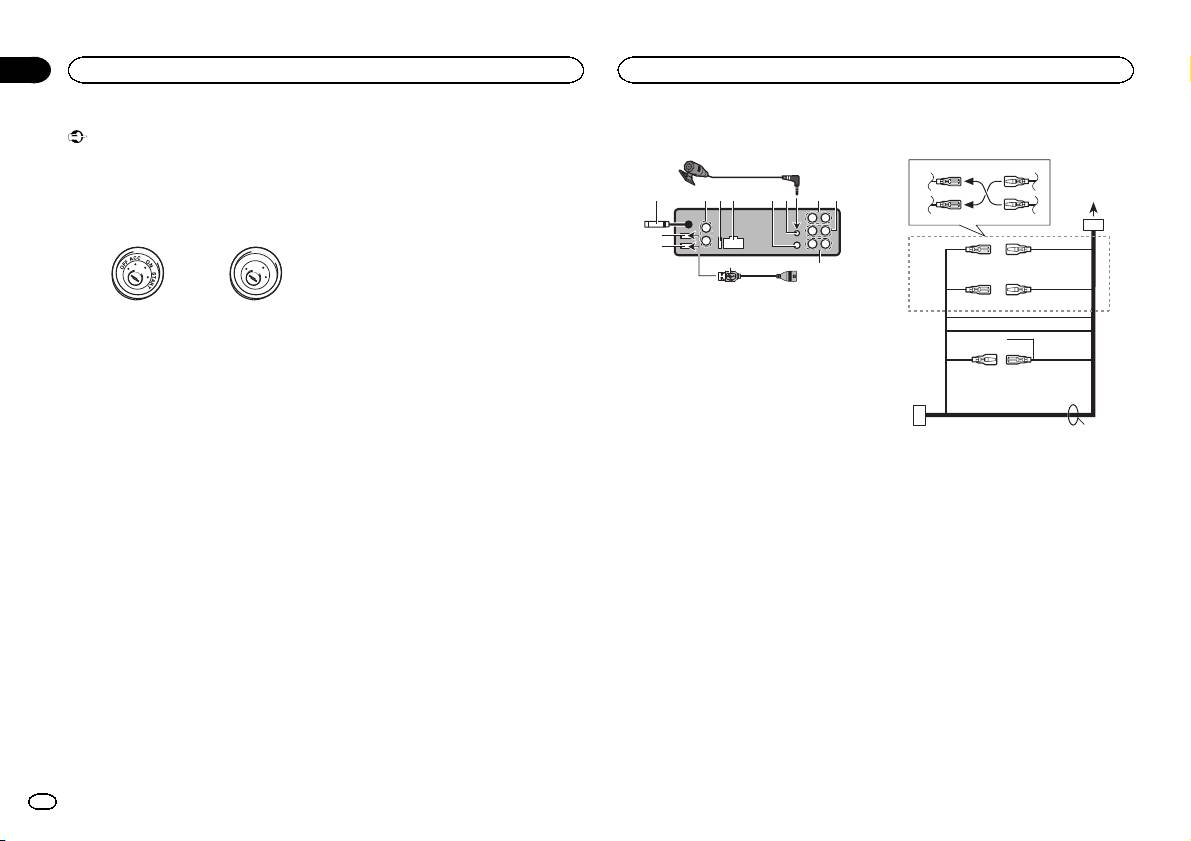
Class: Auto, Moto equipment and Transportation
Type:


Manual for Pioneer DEH-80PRS

CD RDS RECEIVER
AUTORADIO CD RDS
SINTOLETTORE CD RDS
English NederlandsDeutschEspañolItalianoFrançais Русский
REPRODUCTOR DE CD CON RECEPTOR RDS
CD RDS-EMPFÄNGER
CD RDS-ONTVANGER
CD RDS ПРИЕМНИК
Installation Manual
Manuel d’installation
DEH-80PRS
Manuale d’installazione
Manual de instalación
Installationsanleitung
Installatiehandleiding
Руководство по установке
Important
— Never wire the negative speaker cable directly
Hard-wired remote control adaptor can be
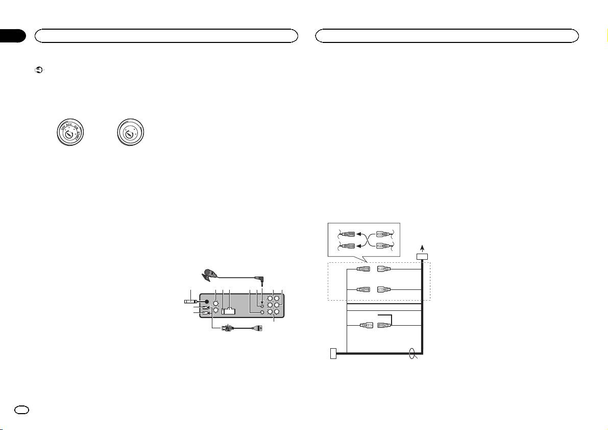
! When installing this unit in a vehicle without
to ground.
connected (sold separately).
an ACC (accessory) position on the ignition
— Never band together negative cables of multi-
8 Microphone input
switch, failure to connect the red cable to the
ple speakers.
9 Microphone
terminal that detects operation of the ignition
! When this unit is on, control signals are sent
4m
key may result in battery drain.
through the blue/white cable. Connect this
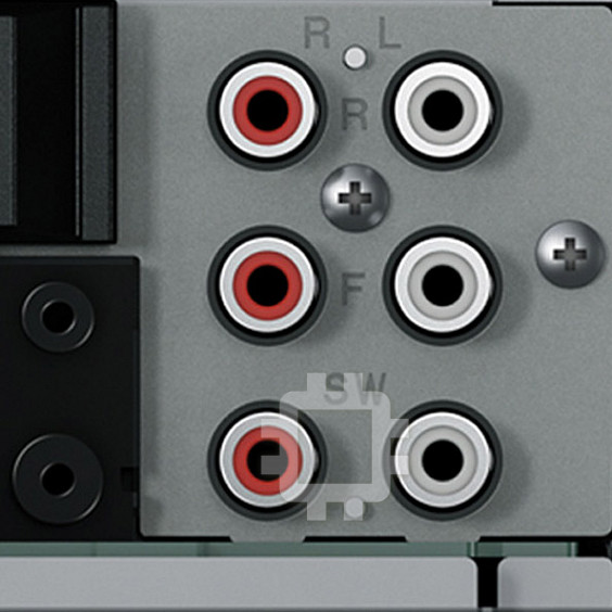
a Rear output or high range output
cable to the system remote control of an ex-
b Front output or middle range output
ternal power amp or the vehicle’s auto-anten-
O
c Subwoofer output or low range output
F
F
N
O
S
T
na relay control terminal (max. 300 mA
d USB cable
A
T
R
12 V DC). If the vehicle is equipped with a
1.5 m
glass antenna, connect it to the antenna
! If connecting both USB1 (USB storage
ACC position No ACC position
booster power supply terminal.
device1)/iPod1 (iPod connected using
! Use of this unit in conditions other than the
! Never connect the blue/white cable to the
USB input1) and USB2 (USB storage de-
following could result in fire or malfunction.
power terminal of an external power amp.
vice2)/iPod2 (iPod connected using USB
— Vehicles with a 12-volt battery and negative
Also, never connect it to the power terminal
input2) at the same time, use a Pioneer
grounding.
of the auto antenna. Doing so may result in
USB cable (CD-U50E) in addition to the
— Speakers with 50 W (output value) and 4 W to
battery drain or a malfunction.
regular Pioneer USB cable.
8 W (impedance value).
! The black cable is ground. Ground cables for
! To prevent a short-circuit, overheating or mal-
this unit and other equipment (especially,
function, be sure to follow the directions
high-current products such as power amps)
Power cord
below.
must be wired separately. If they are not, an
3
4
— Disconnect the negative terminal of the bat-
accidental detachment may result in a fire or
tery before installation.
malfunction.
— Secure the wiring with cable clamps or adhe-
1
sive tape. Wrap adhesive tape around wiring
2
5
6
This unit
that comes into contact with metal parts to
protect the wiring.
9
— Place all cables away from moving parts,
3
4
such as the shift lever and seat rails.
3
4
5 6a7 b
8
— Place all cables away from hot places, such
7
5
6
as near the heater outlet.
8
— Do not connect the yellow cable to the battery
2
9
by passing it through the hole to the engine
1
c
compartment.
d
c
— Cover any disconnected cable connectors
a
b
with insulating tape.
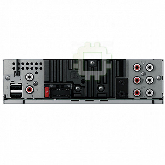
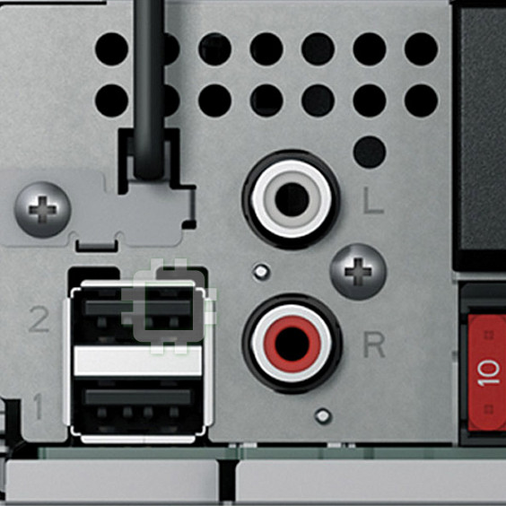
1 USB port 1
— Do not shorten any cables.
2 USB port 2
e
— Never cut the insulation of the power cable of
3 Antenna input
this unit in order to share the power with
15 cm
other devices. The current capacity of the
4 Audio input
cable is limited.
5 Fuse (10 A)
— Use a fuse of the rating prescribed.
6 Power cord input
7 Wired remote input
d
Section
01
Connections
Connections
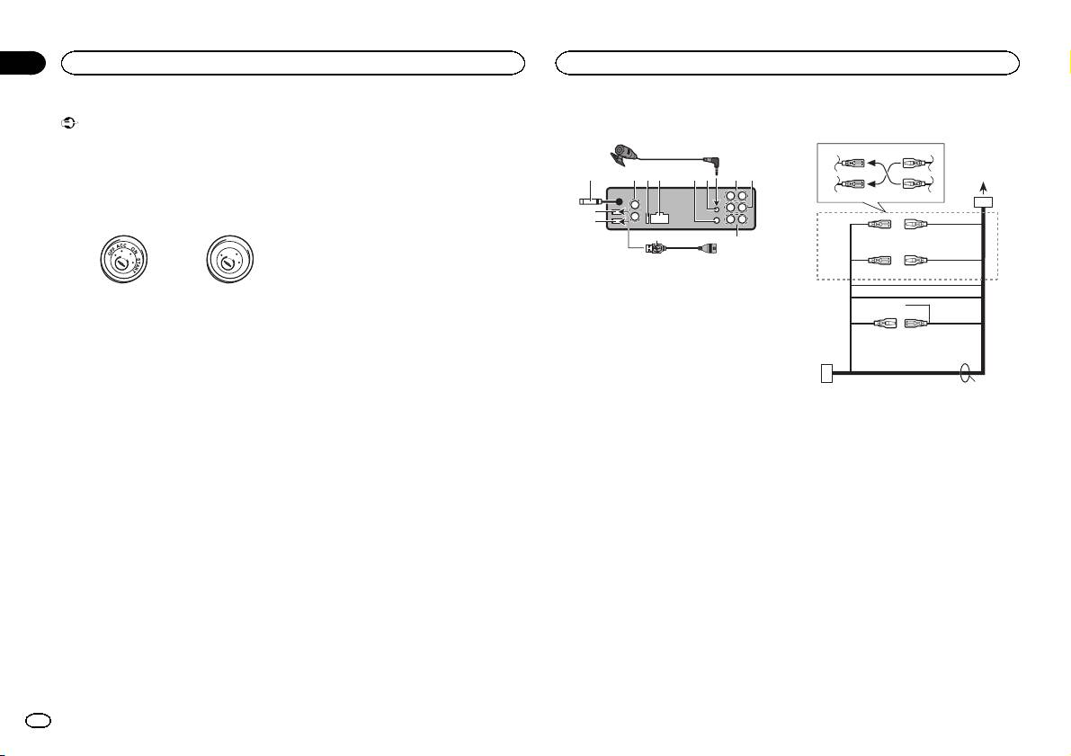
2 Depending on the kind of vehicle, the func-
tion of 3 and 5 may be different. In this
case, be sure to connect 4 to 5 and 6 to
3.
3 Yellow
Back-up (or accessory)
4 Yellow
Connect to the constant 12 V supply termi-
nal.
5 Red
Accessory (or back-up)
6 Red
Connect to terminal controlled by ignition
switch (12 V DC).
7 Connect leads of the same color to each
other.
8 Orange/white
Connect to lighting switch terminal.
9 Black (chassis ground)
a Blue/white
The pin position of the ISO connector will dif-
fer depending on the type of vehicle. Connect
a and b when Pin 5 is an antenna control
type. In another type of vehicle, never con-
nect a and b.
b Blue/white
Connect to system control terminal of the
power amp (max. 300 mA 12 V DC).
c Blue/white
Connect to auto-antenna relay control termi-
nal (max. 300 mA 12 V DC).
d Speaker leads
White: Front left + or middle range lef t +
White/black: Front left * or middle range left
*
Gray: Front right + or middle range right +
Gray/black: Front right * middle range right
*
Green: Rear left + or high range lef t +
Green/black: Rear left * or high range left *
1 To power cord input
Violet: Rear right + or high range right +
Violet/black: Rear right * or high range right
*
2
En
Section
Connections
Connections
01
e ISO connector
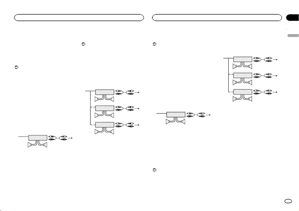
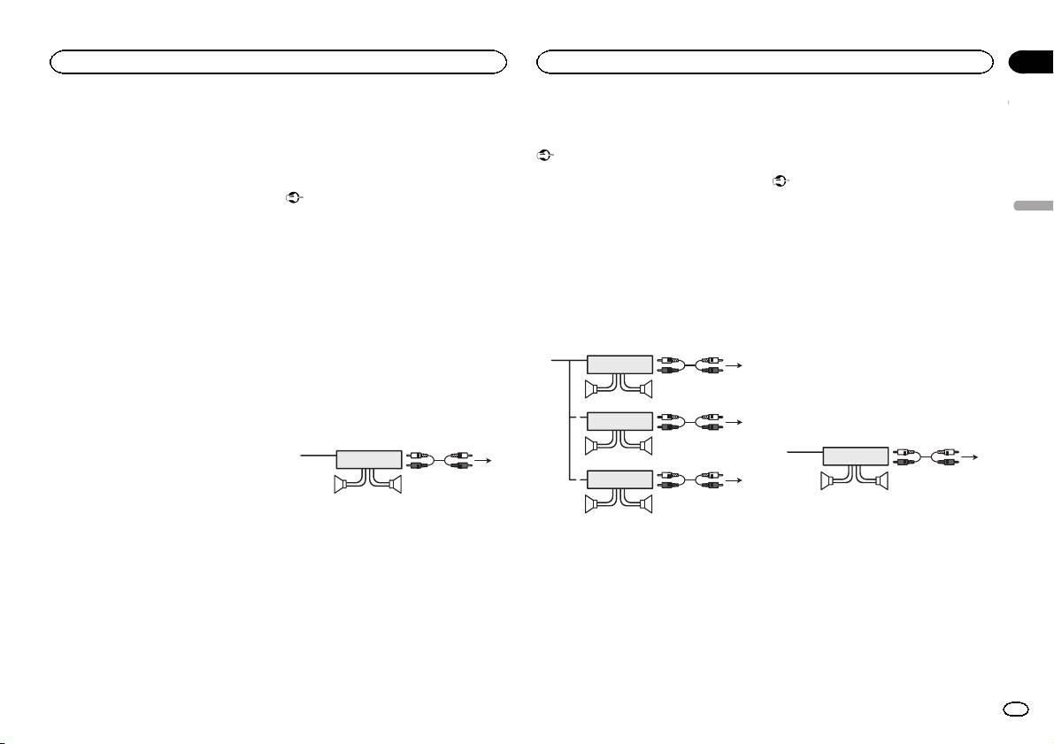
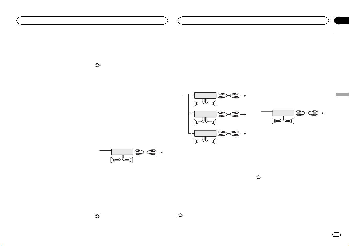
Standard mode without internal
3-way network mode with
! If using this system, we recommend that this
In some vehicles, the ISO connector may be
unit’s internal amp is turned off.
English
amp
internal amp
divided into two. In this case, be sure to con-
For details, refer to the operation manual.
Important
Important
nect to both connectors.
! The speaker leads are not used when this
! Change the DSP switch to standard mode
! Change the DSP switch to 3-way network
connection is in use.
(STD).
mode (NW).
Power amp (sold separately)
For more details on change settings, refer to
For more details on change settings, refer to
1
3
the operation manual or Switching the DSP
the operation manual or Switching the DSP
2
Standard mode with internal amp
setting mode on this page.
setting mode on this page.
4
Important
! If using this system, we recommend that this
! The following signals are output from the
55
! Change the DSP switch to standard mode
unit’s internal amp is turned off.
speaker leads when this connection is in
3
(STD).
For details, refer to the operation manual.
use.
1
2
For more details on change settings, refer to
! The speaker leads are not used when this
White: Middle range left +
6
the operation manual or Switching the DSP
connection is in use.
White/black: Middle range left *
77
Gray: Middle range right +
setting mode on this page.
3
1
3
! The following signals are output from the
Gray/black: Middle range right *
2
2
speaker leads when this connection is in
Green: High range left +
1
4
8
use.
Green/black: High range left *
55
99
White: Front left +
Violet: High range right +
White/black: Front left *
3
Violet/black: High range right *
Gray: Front right +
1
2
6
1
3
1 System remote control
Gray/black: Front right *
Green: Rear lef t +
77
2
Connect to Blue/white cable.
4
Green/black: Rear left *
2 Power amp (sold separately)
3
55
3 Connect with RCA cable (sold separately)
Violet: Rear right +
2
4 To high range output
Violet/black: Rear right *
1
8
5 High range speaker
99
1
3
1 System remote control
6 To middle range output
2
Connect to Blue/white cable.
7 Middle range speaker
4
2 Power amp (sold separately)
8 To low range output
1 System remote control
55
3 Connect with RCA cable (sold separately)
9 Low range speaker
Connect to Blue/white cable.
4 To low range output
2 Power amp (sold separately)
5 Low range speaker
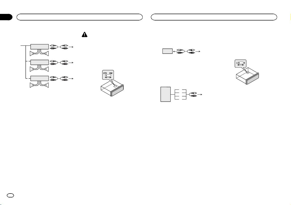
Switching the DSP setting mode
3 Connect with RCA cable (sold separately)
1 System remote control
This unit features two operation modes: the 3-
4 To Rear output
Connect to Blue/white cable.
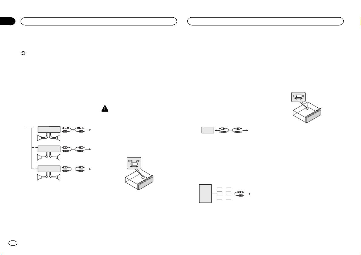
3-way network mode without
way network mode (NW) and the standard mode
5 Rear speaker
2 Power amp (sold separately)
internal amp
(STD). You can switch between modes as de-
6 To Front output
3 Connect with RCA cable (sold separately)
sired. Initially, the DSP setting is set to the
7 Front speaker
Important
4 To subwoofer output
standard mode (STD).
8 To subwoofer output
! Change the DSP switch to 3-way network
5 Subwoofer
! After switching, reset the microprocessor.
9 Subwoofer
mode (NW).
For more details on change settings, refer to
the operation manual or Switching the DSP
setting mode on this page.
En
3
2 To audio output
Important
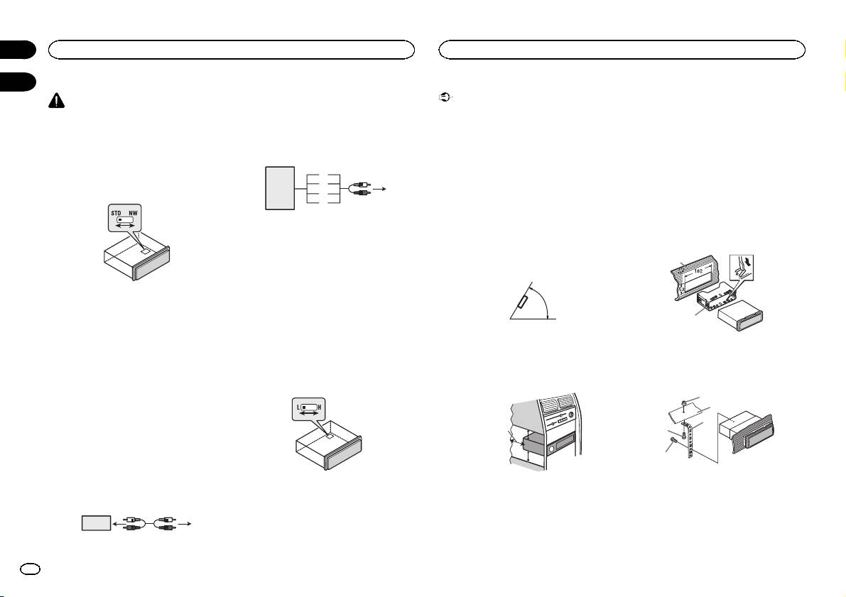
WARNING
3 Connect with RCA cable (sold separately)
! Check all connections and systems before
Do not use the unit in standard mode when a
4 To audio input
final installation.
speaker system for 3-way network mode is con-
! Do not use unauthorized parts as this may
nected to this unit. This may cause damage to
If connecting the unit to a car
cause malfunctions.
the speakers.
stereo with no RCA output
! Consult your dealer if installation requires
drilling of holes or other modifications to the
1 Use a thin, flathead screwdriver to
3
vehicle.
change the DSP switch on the bottom of this
7
8
2
4
! Do not install this unit where:
unit.
1
5
— it may interfere with operation of the vehicle.
6
— it may cause injury to a passenger as a result
of a sudden stop.
1 Car stereo with no RCA output
! The semiconductor laser will be damaged if
2 To speaker output
it overheats. Install this unit away from hot
3 Red: Right +
places such as near the heater outlet.
4 Black: Right *
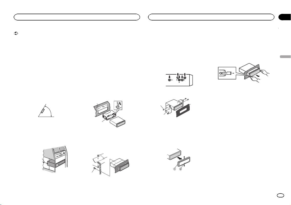
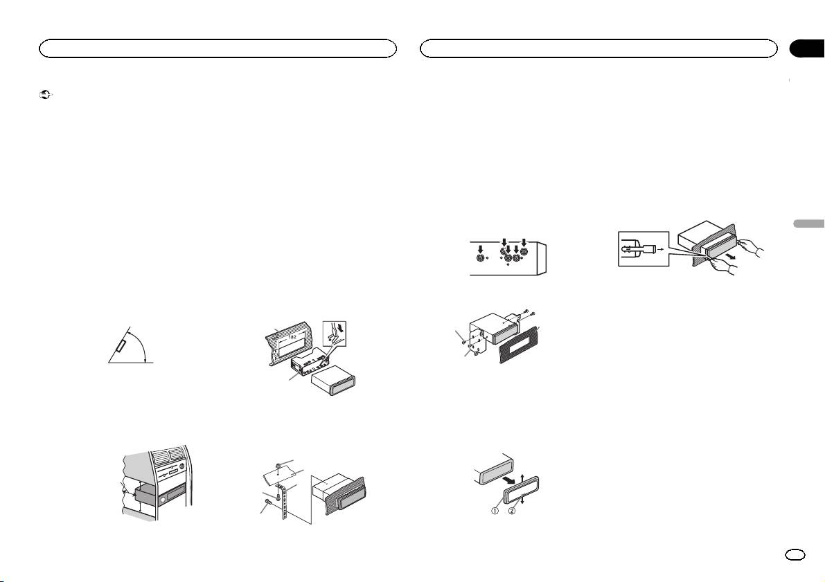
! Optimum performance is obtained when the
5 Black: Left *
unit is installed at an angle of less than 60°.
6 White: Left +
7 Speaker-RCA conversion cable (supplied)
60°
2 Press RESET with a pen tip or other
19 cm
pointed instrument.
8 To audio input
For details, refer to the operation manual.
Switching between RCA input
! When installing, to ensure proper heat dis-
modes
persal when using this unit, make sure you
Audio input
leave ample space behind the rear panel and
% Use a thin, flathead screwdriver to
If you connect the unit to an audio device with
wrap any loose cables so they are not block-
change the RCA input mode switch on the
RCA output, or to one with no RCA output, you
ing the vents.
bottom of this unit.
can set it up so that the audio from the audio de-
vice is output through speakers connected to
the unit. Change settings as necessary based on
whether the connected device has RCA output
or not.
For more details on change settings, refer to the
operation manual or Switching between RCA
input modes on this page.
If connecting the unit to a car
! L (Low) - If inputting from the RCA output of a
stereo with RCA output
connected device
! H (High) - If inputting from the speaker out-
23 4
put of a connected device
1
1 Car stereo with RCA output
5cmcm
Section
01
Connections
Installation
02
Use commercially available parts when instal-
ling.
DIN Front-mount
1 Insert the mounting sleeve into the dash-
board.
For installation in shallow spaces, use the sup-
plied mounting sleeve. If there is enough space,
use the mounting sleeve that came with the ve-
hicle.
2 Secure the mounting sleeve by using a
screwdriver to bend the metal tabs (90°) into
place.
1
2
1 Dashboard
2 Mounting sleeve
3 Install the unit as illustrated.
1
2
3
Leave ample
4
5 cm
space
5 cm
5
1 Nut
2 Firewall or metal support
3 Metal strap
DIN front/rear mount
4 Screw
5 Screw (M4 × 8)
This unit can be properly installed using either
front-mount or rear-mount installation.
4
En
Section
Installation
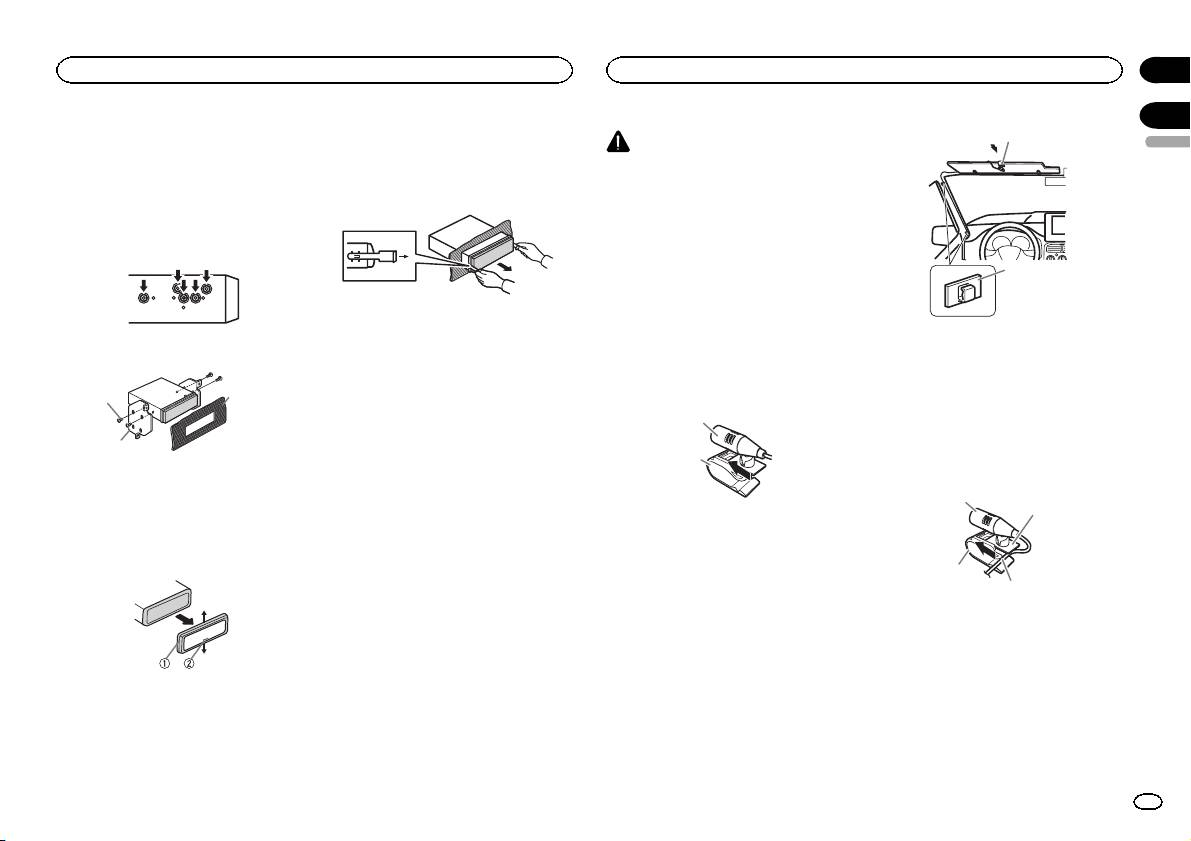
Installing the microphone
02
03
# Make sure that the unit is installed securely in
2 Insert the supplied extraction keys into
1
place. An unstable installation may cause skipping
CAUTION
both sides of the unit until they click into
English
or other malfunctions.
place.
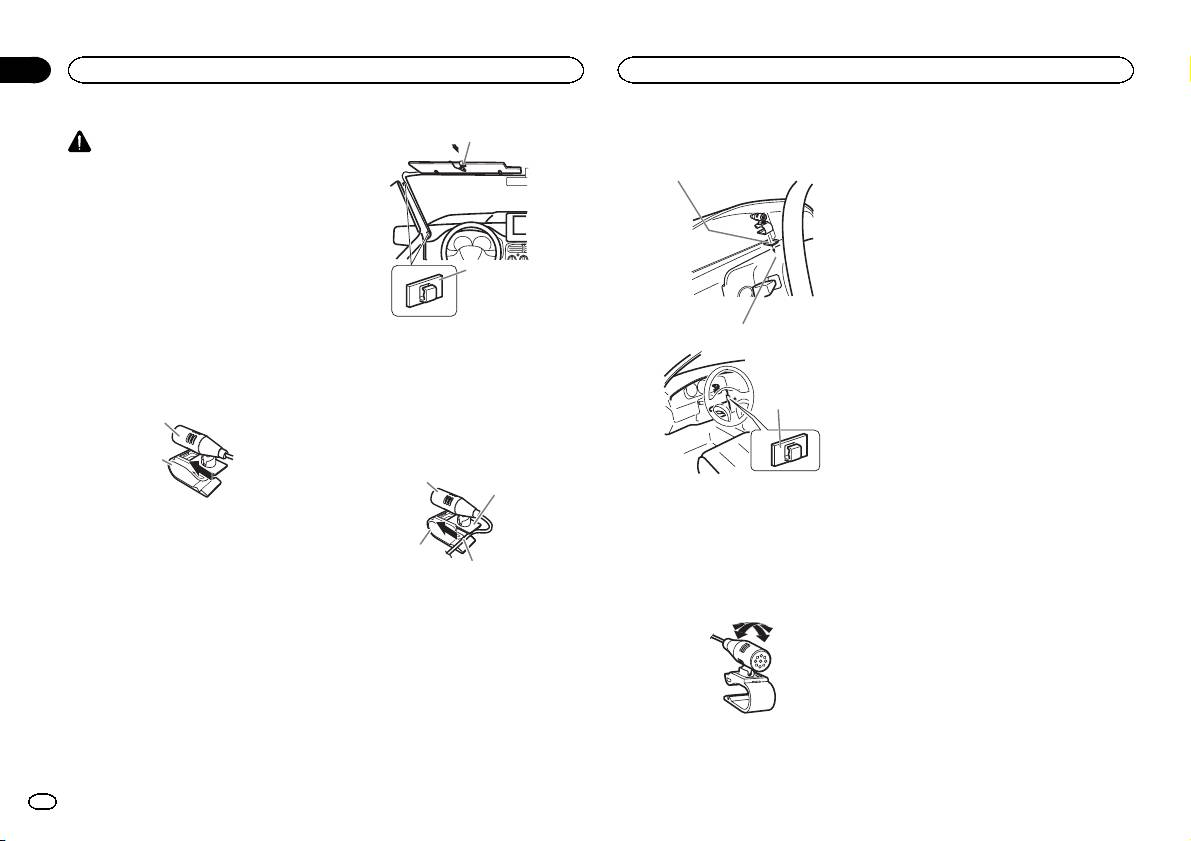
It is extremely dangerous to allow the micro-
phone lead to become wound around the steer-
3 Pull the unit out of the dashboard.
ing column or shift lever. Be sure to install the
DIN Rear-mount
unit in such a way that it will not obstruct driv-
1 Determine the appropriate position
ing.
where the holes on the bracket and the side
Note
of the unit match.
Install the microphone in a position and orienta-
2
tion that will enable it to pick up the voice of the
person operating the system.
Removing and re-attaching the
When installing the
1 Microphone clip
front panel
2 Tighten two screws on each side.
microphone on the sun visor
2 Clamp
You can remove the front panel to protect your
unit from theft.
1 Install the microphone on the micro-
3
Press the detach button and push the front
phone clip.
When installing the
1
panel upward and pull it toward you.
microphone on the steering
For details, refer to operation manual.
1
column
2
2
1 Install the microphone on the micro-
1 Tapping screw (5 mm × 8 mm)
phone clip.
2 Mounting bracket
1
3 Dashboard or console
2
1 Microphone
Removing the unit
2 Microphone clip
1 Remove the trim ring.
2 Install the microphone clip on the sun
3
visor.
4
With the sun visor up, install the microphone
clip. (Lowering the sun visor reduces the voice
1 Microphone
recognition rate.)
2 Microphone base
3 Microphone clip
4 Fit the microphone lead into the groove.
# Microphone can be installed without using mi-
1 Trim ring
crophone clip. In this case, detach the microphone
2 Notched tab
base from the microphone clip. To detach the micro-
! Releasing the front panel allows easier ac-
phone base from the microphone clip, slide the mi-
cess to the trim ring.
crophone base.
! When reattaching the trim ring, point the
side with the notched tab down.
En
5
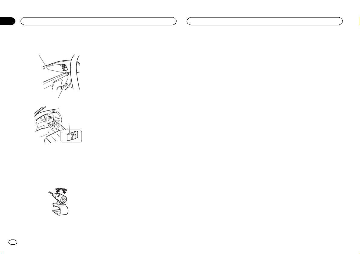
2 Install the microphone clip on the steer-
ing column.
1
2
Section
03
Installing the microphone
3
1 Double-sided tape
2 Install the microphone clip on the rear side of
the steering column.
3 Clamp
Adjusting the microphone
angle
The microphone angle can be adjusted.
6
En
English
7En

Important
— Ne coupez jamais l’isolation du câble d’ali-
Cet appareil
Cordon d’alimentation
! Lors de l’installation de cet appareil dans un
mentation de cet appareil pour partager l’ali-
véhicule sans position ACC (accessoire) sur
mentation avec d’autres appareils. La
9
3
4
le contact d’allumage, ne pas connecter le
capacité en courant du câble est limitée.
câble rouge à la borne qui détecte l’utilisa-
— Utilisez un fusible correspondant aux caracté-
3
4
5 6a7 b
8
tion de la clé de contact peut entraîner le dé-
ristiques spécifiées.
1
2
5
6
chargement de la batterie.
— Ne câblez jamais le câble négatif du haut-par-
2
leur directement à la masse.
1
— Ne réunissez jamais ensemble les câbles né-
F
F
O
N
O
d
3
4
S
T
gatifs de plusieurs haut-parleurs.
c
A
T
R
! Lorsque cet appareil est sous tension, les si-
gnaux de commande sont transmis via le
1 Port USB 1
7
5
6
Avec position ACC Sans position ACC
câble bleu/blanc. Connectez ce câble à la té-
2 Port USB 2
8
! L’utilisation de cet appareil dans des condi-
lécommande du système d’un amplificateur
3 Entrée antenne
9
tions autres que les conditions suivantes
de puissance externe ou à la borne de
15 cm
c
pourrait provoquer un incendie ou un mau-
commande du relais de l’antenne motorisée
4 Entrée audio
a
b
vais fonctionnement.
du véhicule (max. 300 mA 12 V CC). Si le véhi-
5 Fusible (10 A)
— Véhicules avec une batterie 12 volts et mise à
cule est équipé d’une antenne intégrée à la
6 Entrée cordon d’alimentation
la masse du négatif.
lunette arrière, connectez-le à la borne d’ali-
7 Entrée télécommande câblée
e
— Haut-parleurs avec une puissance de sortie
mentation de l’amplificateur d’antenne.
Un adaptateur de télécommande câblée
de 50 W et une impédance de 4 W à8W.
! Ne reliez jamais le câble bleu/blanc à la
(vendu séparément) peut être connecté.
! Pour éviter un court-circuit, une surchauffe
borne d’alimentation d’un amplificateur de
8 Entrée microphone
ou un dysfonctionnement, assurez-vous de
puissance externe. De même, ne le reliez pas
9 Microphone
respecter les instructions suivantes.
à la borne d’alimentation de l’antenne moto-
4m
— Déconnectez la borne négative de la batterie
risée. Dans le cas contraire, il peut en résul-
a Sortie arrière ou sortie des aigus
avant l’installation.
ter un déchargement de la batterie ou un
b Sortie avant ou sortie des médiums
— Fixez le câblage avec des serre-fils ou de la
dysfonctionnement.
c Sortie des extrêmes graves ou sortie des gra-
bande adhésive. Pour protéger le câblage, en-
! Le câble noir est la masse. Les câbles de
ves
roulez dans du ruban adhésif les parties du
terre de cet appareil et d’autres produits (par-
d Câble USB
câblage en contact avec des pièces en métal.
ticulièrement les produits avec des courants
1,5 m
— Placez les câbles à l’écart de toutes les par-
élevés tels que l’amplificateur de puissance)
! Si USB1 (périphérique de stockage USB
ties mobiles, telles que le levier de vitesse et
doivent être câblés séparément. Dans le cas
1)/iPod1 (iPod connecté via l’entrée USB
les rails des sièges.
contraire, ils peuvent se détacher accidentel-
1) et USB2 (périphérique de stockage
— Placez les câbles à l’écart de tous les endroits
lement et provoquer un incendie ou un dys-
USB 2)/iPod2 (iPod connecté via l’entrée
chauds, par exemple les sorties de chauf-
fonctionnement.
USB 2) sont connectés simultanément,
fage.
utilisez un câble USB Pioneer (CD-U50E)
— Ne reliez pas le câble jaune à la batterie à tra-
en plus du câble standard USB Pioneer.
vers le trou dans le compartiment moteur.
— Recouvrez tous les connecteurs de câbles qui
ne sont pas connectés avec du ruban adhésif
isolant.
— Ne raccourcissez pas les câbles.
d
Section
01
Connexions
Connexions
1 Vers l’entrée cordon d’alimentation
2 Selon le type de véhicule, 3 et 5 peuvent
avoir une fonction différente. Dans ce cas,
assurez-vous de connecter 4 à 5 et 6 à 3.
3 Jaune
Alimentation de secours (ou accessoire)
4 Jaune
Connectez à la borne d’alimentation 12 V per-
manente.
5 Rouge
Accessoire (ou alimentation de secours)
6 Rouge
Connectez à la borne contrôlée par le
contact d’allumage (12 V CC).
7 Connectez les fils de même couleur en-
semble.
8 Orange/blanc
Connectez à la borne du commutateur d’é-
clairage.
9 Noir (masse du châssis)
8
Fr
Section
Connexions
Connexions
01
a Bleu/blanc
9 Haut-parleur d’extrêmes graves
Amplificateur de puissance
Mode standard sans
La position des broches du connecteur ISO
(vendu séparément)
amplificateur interne
est différente selon le type de véhicule.
Mode réseau de séparation à 3
Important
Connectez a et b lorsque la broche 5 est de
Mode standard avec un
voies avec un amplificateur interne
type commande de l’antenne. Dans un type
! Changez la position du commutateur DSP
amplificateur interne
Important
différent de véhicule, ne connectez jamais a
sur le mode standard (STD).
et b.
Important
Pour plus de détails sur la modification des
! Changez la position du commutateur DSP
réglages, reportez-vous au mode d’emploi ou
sur le mode réseau de séparation à 3 voies
b Bleu/blanc
! Changez la position du commutateur DSP
Français
(NW).
Connectez à la prise de commande du sys-
sur le mode standard (STD).
à la page suivante, Changement du mode de
Pour plus de détails sur la modification des
tème de l’amplificateur de puissance (max.
Pour plus de détails sur la modification des
fonctionnement du DSP.
réglages, reportez-vous au mode d’emploi ou
300 mA 12 V CC).
réglages, reportez-vous au mode d’emploi ou
! Si vous utilisez ce système, nous vous re-
à la page suivante, Changement du mode de
c Bleu/blanc
à la page suivante, Changement du mode de
commandons de mettre l’amplificateur in-
fonctionnement du DSP.
Connectez à la borne de commande du relais
fonctionnement du DSP.
terne de cet appareil hors service.
! Les signaux suivants sont émis par les fils
de l’antenne motorisée (max. 300 mA 12 V
! Les signaux suivants sont émis par les fils
Pour plus de détails, reportez-vous au mode
CC).
des haut-parleurs lorsque la connexion est
d’emploi.
des haut-parleurs lorsque la connexion est
établie.
d Fils des haut-parleurs
établie.
! Les fils des haut-parleurs ne sont pas utilisés
Blanc : Avant gauche + ou médiums gauche
Blanc : Avant gauche +
lorsque la connexion n’est pas établie.
Blanc : Médiums gauche +
Blanc/noir : Médiums gauche *
+
Blanc/noir : Avant gauche *
1
3
Gris : Médiums droite +
Blanc/noir : Avant gauche * ou médiums
Gris : Avant droite +
2
Gris/noir : Médiums droite *
gauche *
Gris/noir : Avant droite *
4
Vert: Arrière gauche +
Vert: Aigus gauche +
Gris : Avant droite + ou médiums droite +
55
Vert/noir: Aigus gauche *
Gris/noir : Avant droite * ou médiums droite
Vert/noir: Arrière gauche *
Violet : Aigus droite +
*
Violet : Arrière droite +
3
Vert: Arrière gauche + ou aigus gauche +
Violet/noir: Arrière droite *
1
2
Violet/noir: Aigus droite *
6
Vert/noir: Arrière gauche * ou aigus gauche
3
1
3
77
1
*
2
Violet : Arrière droite + ou aigus droite +
2
3
4
4
Violet/noir: Arrière droite * ou aigus droite
2
55
55
*
1
8
e Connecteur ISO
99
Dans certains véhicules, il est possible que
1 Télécommande du système
le connecteur ISO soit divisé en deux. Dans
1 Télécommande du système
Connectez au câble bleu/blanc.
ce cas, assurez-vous de connecter les deux
Connectez au câble bleu/blanc.
1 Télécommande du système
2 Amplificateur de puissance (vendu séparé-
connecteurs.
2 Amplificateur de puissance (vendu séparé-
Connectez au câble bleu/blanc.
ment)
ment)
2 Amplificateur de puissance (vendu séparé-
3 Connectez avec un câble RCA (vendu séparé-
3 Connectez avec un câble RCA (vendu séparé-
ment)
ment)
ment)
3 Connectez avec un câble RCA (vendu séparé-
4 Vers la sortie des graves
4 Vers la sortie haut-parleur d’extrêmes graves
ment)
5 Haut-parleur de graves
5 Haut-parleur d’extrêmes graves
4 Vers la sortie arrière
5 Haut-parleur arrière
6 Vers la sortie avant
7 Haut-parleur avant
8 Vers la sortie haut-parleur d’extrêmes graves
Fr
9
Section
01
Connexions
Connexions
Mode réseau de séparation à 3
8 Vers la sortie des graves
7 Câble de conversion haut-parleur - RCA
Entrée audio
9 Haut-parleur de graves
(fourni)
voies sans amplificateur interne
Si vous connectez l’appareil à un périphérique
19 cm
Important
audio via la sortie RCA ou à un périphérique
Changement du mode de
8 Vers l’entrée audio
! Changez la position du commutateur DSP
audio sans sortie RCA, vous pouvez effectuer la
fonctionnement du DSP
sur le mode réseau de séparation à 3 voies
configuration pour que le son du périphérique
Changement entre les modes
(NW).
Cet appareil présente deux modes de fonction-
audio soit émis par les haut-parleurs connectés
entrée RCA
Pour plus de détails sur la modification des
nement : le mode réseau de séparation à 3 voies
àl’appareil. Modifiez les réglages au besoin
réglages, reportez-vous au mode d’emploi ou
(NW) et le mode standard (STD). Vous pouvez
selon si le périphérique connecté possède une
% Utilisez un tournevis plat fin pour chan-
à cette page, Changement du mode de fonc-
passer d’un mode à l’autre comme vous voulez.
sortie RCA ou non.
ger la position du commutateur de mode en-
tionnement du DSP.
Initialement, le DSP est réglé sur le mode stan-
Pour plus de détails sur la modification des ré-
trée RCA sur le fond de l’appareil.
! Si vous utilisez ce système, nous vous re-
dard (STD).
glages, reportez-vous au mode d’emploi ou à
commandons de mettre l’amplificateur in-
! Après le changement de mode, réinitialisez
cette page, Changement entre les modes entrée
terne de cet appareil hors service.
le microprocesseur.
RCA.
Pour plus de détails, reportez-vous au mode
d’emploi.
Lors de la connexion de
ATTENTION
! Les fils des haut-parleurs ne sont pas utilisés
l’appareil à un système stéréo
N’utilisez pas l’appareil en mode standard
lorsque la connexion n’est pas établie.
quand un système de haut-parleurs pour le
du véhicule avec la sortie RCA
3
mode réseau de séparation à 3 voies est
1
23 4
connecté à l’appareil. Cela pourrait endomma-
2
1
! L (Bas) - Pour l’émission depuis la sortie RCA
4
ger les haut-parleurs.
d’un périphérique connecté
55
! H (Haut) - Pour l’émission depuis la sortie
1 Système stéréo de véhicule avec sortie RCA
1 Utilisez un tournevis plat fin pour chan-
3
2 Vers la sortie audio
des haut-parleurs d’un périphérique
ger la position du commutateur DSP sur le
3 Connectez avec un câble RCA (vendu séparé-
connecté
1
2
fond de l’appareil.
6
ment)
77
4 Vers l’entrée audio
3
Lors de la connexion de
2
1
8
l’appareil à un système stéréo
99
du véhicule sans sortie RCA
3
7
8
1 Télécommande du système
2
4
1
Connectez au câble bleu/blanc.
5
2 Appuyez sur RESET avec la pointe d’un
6
2 Amplificateur de puissance (vendu séparé-
stylo ou un autre instrument pointu.
ment)
Pour plus de détails, reportez-vous au mode
3 Connectez avec un câble RCA (vendu séparé-
1 Système stéréo de véhicule sans sortie RCA
d’emploi.
ment)
2 Vers la sortie des haut-parleurs
4 Vers la sortie des aigus
3 Rouge: + droit
5 Haut-parleur d’aigus
4 Noir: * droit
6 Vers la sortie des médiums
5 Noir: * gauche
7 Haut-parleur de médiums
6 Blanc : + gauche
10
Fr
Important
! Vérifiez toutes les connexions et tous les sys-
tèmes avant l’installation finale.
! N’utilisez pas de pièces non autorisées car il
peut en résulter des dysfonctionnements.
! Consultez votre revendeur si l’installation né-
cessite le perçage de trous ou d’autres modi-
fications du véhicule.
! N’installez pas cet appareil là où :
— il peut interférer avec l’utilisation du véhicule.
— il peut blesser un passager en cas d’arrêt
soudain du véhicule.
! Le laser à semi-conducteur sera endommagé
s’il devient trop chaud. Installez cet appareil
àl’écart de tous les endroits chauds, par
exemple les sorties de chauffage.
! Des performances optimales sont obtenues
quand l’appareil est installé à un angle infé-
rieur à 60°.
60°
! Lors de l’installation, pour assurer une dis-
persion correcte de la chaleur quand cet ap-
pareil est utilisé, assurez-vous de laisser un
espace important derrière la face arrière et
enroulez les câbles volants de façon qu’ils ne
bloquent pas les orifices d’aération.
5cmcm
Section
Installation
Installation
02
4 Vis
! Quand vous remontez l’anneau de garniture,
Montage avant/arrière DIN
5 Vis (M4 × 8)
pointez le côté avec l’encoche vers le bas.
Cet appareil peut être installé correctement soit
# Assurez-vous que l’appareil est correctement mis
en montage frontal ou en montage arrière.
en place. Toute installation instable peut entraîner
2 Insérez les clés d’extraction fournies dans
Utilisez des pièces disponibles dans le
des sauts ou autres dysfonctionnements.
les deux côtés de l’appareil jusqu’àcequ’el-
commerce lors de l’installation.
les s’enclenchent en place.
Montage arrière DIN
Montage frontal DIN
3 Tirez l’appareil hors du tableau de bord.
Français
1 Déterminez la position appropriée où les
1 Insérez le manchon de montage dans le
trous sur le support et sur le côté de l’appa-
tableau de bord.
reil se correspondent.
Lors de l’installation de cet appareil dans un es-
pace peu profond, utilisez le manchon de mon-
tage fourni. Si l’espace est suffisant, utilisez le
manchon de montage fourni avec le véhicule.
2 Fixez le manchon de montage en utilisant
Retrait et remontage de la face
un tournevis pour courber les pattes métalli-
2 Serrez deux vis de chaque côté.
avant
ques (90°) en place.
Vous pouvez retirer la face avant pour protéger
l’appareil contre le vol.
1
3
1
Appuyez sur la touche de retrait, puis poussez la
face avant vers le haut et tirez-la vers vous.
Pour plus de détails, reportez-vous au mode
2
d’emploi.
2
1 Vis taraudeuse (5 mm × 8 mm)
2 Support de montage
3 Tableau de bord ou console
1 Tableau de bord
2 Manchon de montage
Retrait de l’appareil
3 Installez l’appareil comme indiqué sur la
1 Retirez l’anneau de garniture.
figure.
1
Laissez suffisamment
2
d’espace
5 cm
3
4
5 cm
5
1 Anneau de garniture
2 Encoche
1 Écrou
! Retirer la face avant permet d’accéder plus
2 Pare-feu ou support métallique
facilement à l’anneau de garniture.
3 Attache en métal
Fr
11
1
2 Installez le clip microphone sur la colonne
PRÉCAUTION
de direction.
Il est extrêmement dangereux de laisser le fil du
microphone s’enrouler autour de la colonne de
1
direction ou du levier de vitesse. Assurez-vous
d’installer cet appareil de telle manière qu’il ne
gêne pas la conduite.
Remarque
Installez le microphone dans une position et
2
une orientation qui lui permette de capter la voix
de la personne qui utilise le système.
Si vous installez le
1 Clip microphone
microphone sur le pare-soleil
2 Serre-fils
1 Installez le microphone sur le clip micro-
phone.
Si vous installez le microphone
sur la colonne de direction
1
1 Installez le microphone sur le clip micro-
2
phone.
1
2
1 Microphone
2 Clip microphone
3
2 Installez le clip microphone sur le pare-
4
soleil.
Avec le pare-soleil relevé, installez le clip micro-
1 Microphone
phone. (Abaisser le pare-soleil réduit le taux de
2 Base pour microphone
reconnaissance vocale.)
3 Clip microphone
4 Insérez le fil du microphone dans la fente.
# Le microphone peut être installé sans le clip mi-
crophone. Dans ce cas, détachez la base pour micro-
phone du clip microphone. Pour détacher la base
pour microphone du clip microphone, faites-la glis-
ser.
2
Section
03
Installation du microphone
Installation du microphone
3
1 Bande double face
2 Installez le clip microphone sur la face arrière
de la colonne de direction.
3 Serre-fils
Réglage de l’angle du
microphone
L’angle du microphone peut être réglé.
12
Fr
Français
13Fr
Importante
— Non condividere mai l’alimentazione con altri
Questa unità
Cavo di alimentazione
! Quando si installa questa unità in un veicolo
dispositivi tagliando l’isolante del cavo di ali-
che non dispone della posizione ACC (acces-
mentazione dell’unità. La capacità di carico
9
3
4
soria) per l’interruttore della chiave di avvia-
di corrente del cavo è limitata.
mento, se non si collega il cavo rosso a un
— Utilizzare esclusivamente un fusibile con la
3
4
5 6a7 b
8
terminale accoppiato al funzionamento del-
portata prescritta.
1
2
5
6
l’interruttore della chiave di avviamento, la
— Non collegare mai direttamente a terra il
2
batteria potrebbe scaricarsi.
cavo negativo dell’altoparlante.
1
— Non legare mai assieme cavi negativi di più
d
3
4
altoparlanti.
c
O
O
F
F
N
S
T
! Quando questa unità è accesa, i segnali di
A
T
R
controllo vengono trasmessi dal cavo blu/
1 Porta USB 1
7
5
6
bianco. Collegare questo cavo al telecoman-
2 Porta USB 2
8
Con posizione ACC Senza posizione ACC
do di sistema di un amplificatore di potenza
3 Ingresso antenna
9
! Se questa unità viene utilizzata in condizioni
esterno o al terminale di controllo del relè
15 cm
c
diverse dalle seguenti, potrebbero verificarsi
dell’antenna automatica del veicolo (max.
4 Ingresso audio
300 mA 12 V CC). Se il veicolo è dotato di
a
b
incendi o malfunzionamenti.
5 Fusibile (10 A)
— Veicoli dotati di batteria da 12 volt e messa a
un’antenna a vetro, collegarla al terminale di
6 Ingresso cavo di alimentazione
terra negativa.
alimentazione di potenza dell’antenna.
7 Ingresso remoto cablato
e
— Altoparlanti con uscita nominale da 50 W e
! Non collegare mai il cavo blu/bianco al ter-
È possibile collegare un adattatore per tele-
impedenza nominale compresa tra 4 W e8W.
minale di alimentazione dell’amplificatore di
comando cablato (venduto a parte).
! Per evitare rischi di cortocircuito, surriscalda-
potenza esterno. Inoltre, non collegarlo mai
8 Ingresso microfono
mento o malfunzionamento, accertarsi di se-
al terminale di alimentazione dell’antenna
9 Microfono
guire le indicazioni riportate di seguito.
automatica. In caso contrario, la batteria po-
4m
— Prima dell’installazione, scollegare il morset-
trebbe scaricarsi o potrebbero verificarsi mal-
a Uscita posteriore o uscita di gamma alta
to negativo della batteria.
funzionamenti.
b Uscita anteriore o uscita di gamma media
— Assicurare i cavi con morsetti per cavi o na-
! Il cavo nero è la messa a terra. I cavi di
c Uscita subwoofer o uscita di gamma bassa
stro adesivo. Per proteggere i cavi, avvolgere
messa a terra per questa unità e per le altre
d Cavo USB
nastro adesivo attorno agli stessi nei punti in
apparecchiature (soprattutto per i prodotti ad
1,5 m
cui entrano in contatto con parti metalliche.
alta tensione, quali l’amplificatore di poten-
! Se si collegano contemporaneamente
— Posizionare tutti i cavi in modo che non pos-
za) devono essere collegati separatamente.
USB1 (dispositivo di memoria USB1)/
sano entrare in contatto con componenti mo-
In caso contrario, se scollegati accidental-
iPod1 (iPod collegato tramite entrata
bili, come la leva del cambio e i binari dei
mente, potrebbero provocare incendi o mal-
USB1) e USB2 (dispositivo di memoria
sedili.
funzionamenti.
USB2)/iPod2 (iPod collegato tramite en-
— Non posizionare i cavi in luoghi soggetti a
trata USB2), oltre al cavo normale USB
surriscaldamento, come le bocchette dell’im-
Pioneer utilizzare il cavo USB Pioneer
pianto di riscaldamento.
(CD-U50E).
— Non collegare il cavo giallo alla batteria fa-
cendolo passare attraverso fori nel vano mo-
tore.
— Rivestire tutti i connettori scollegati con na-
stro isolante.
— Non accorciare i cavi.
d
Sezione
01
Collegamenti
Collegamenti
1 All’ingresso del cavo di alimentazione
2 A seconda del tipo di veicolo, la funzione di
3 e 5 potrebbe essere diversa. In questo
caso, accertarsi di collegare 4 a 5 e 6 a 3.
3 Giallo
Riserva (o accessorio)
4 Giallo
Collegare al terminale di alimentazione co-
stante 12 V.
5 Rosso
Accessorio (o riserva)
6 Rosso
Collegare al terminale controllato dall’inter-
ruttore di accensione (12 V CC).
7 Collegare insieme i cavi dello stesso colore.
8 Arancione/bianco
Collegare al terminale dell’interruttore di illu-
minazione.
9 Nero (messa a terra telaio)
14
It
Sezione
Collegamenti
Collegamenti
01
a Blu/bianco
Per ulteriori dettagli su come modificare le
Amplificatore di potenza
Per ulteriori dettagli su come modificare le
La posizione dei pin del connettore ISO sarà
impostazioni, vedere il manuale d’istruzioni o
impostazioni, vedere il manuale d’istruzioni o
(venduto a parte)
diversa a seconda del tipo di veicolo. Collega-
la sezione Commutazione della modalità d’im-
la sezione Commutazione della modalità d’im-
re a e b quando il Pin 5 è del tipo controllo
postazione DSP nella pagina seguente.
postazione DSP nella pagina seguente.
Modalità standard con
antenna. In un altro tipo di veicolo, non colle-
! Se si utilizza questo sistema, si raccomanda
! I seguenti segnali vengono emessi dai cavi
amplificatore interno
gare mai a e b.
di disattivare l’amplificatore interno dell’uni-
degli altoparlanti quando si utilizza questa
b Blu/bianco
Importante
tà.
connessione.
Collegare al terminale di controllo del siste-
! Impostare l’interruttore DSP sulla modalità
Per ulteriori dettagli, vedere il manuale d’i-
Bianco: Sinistro di gamma media +
ma dell’amplificatore di potenza (max.
standard (STD).
struzioni.
Bianco/nero: Sinistro di gamma media *
300 mA 12 V di c.c.).
Per ulteriori dettagli su come modificare le
! I cavi degli altoparlanti non vengono utilizzati
Grigio: Destro di gamma media +
c Blu/bianco
impostazioni, vedere il manuale d’istruzioni o
quando si utilizza questa connessione.
Grigio/nero: Destro di gamma media *
Collegare al terminale di controllo del relè
la sezione Commutazione della modalità d’im-
Verde: Sinistro di gamma alta +
1
3
dell’antenna automatica (max. 300 mA 12 V
postazione DSP nella pagina seguente.
Verde/nero: Sinistro di gamma alta *
di c.c.).
! I seguenti segnali vengono emessi dai cavi
2
Viola: Destro di gamma alta +
Italiano
4
d Cavi altoparlanti
degli altoparlanti quando si utilizza questa
Viola/nero: Destro di gamma alta *
55
Bianco: Anteriore sinistro + o sinistro di
connessione.
3
gamma media +
Bianco: Anteriore sinistro +
3
1
Bianco/nero: Anteriore sinistro * o sinistro
Bianco/nero: Anteriore sinistro *
2
1
2
4
di gamma media *
Grigio: Anteriore destro +
6
55
Grigio: Anteriore destro + o destro di
Grigio/nero: Anteriore destro *
77
gamma media +
Verde: Posteriore sinistro +
3
Grigio/nero: Anteriore destro * o destro di
Verde/nero: Posteriore sinistro *
2
gamma media *
Viola: Posteriore destro +
1
1 Telecomando sistema
8
Verde: Posteriore sinistro + o sinistro di
Viola/nero: Posteriore destro *
Collegare al cavo Blu/bianco.
99
gamma alta +
2 Amplificatore di potenza (venduto a parte)
3
Verde/nero: Posteriore sinistro * o sinistro di
1
3 Collegare con un cavo RCA (venduto a parte)
gamma alta *
2
4 All’uscita di gamma bassa
4
1 Telecomando sistema
Viola: Posteriore destro + o destro di gamma
5 Altoparlante di gamma bassa
55
Collegare al cavo Blu/bianco.
alta +
2 Amplificatore di potenza (venduto a parte)
Viola/nero: Posteriore destro * o destro di
Modalità rete a 3 vie senza
3 Collegare con un cavo RCA (venduto a parte)
gamma alta *
amplificatore interno
4 All’uscita posteriore
e Connettore ISO
1 Telecomando sistema
5 Altoparlante posteriore
Importante
In alcuni veicoli, il connettore ISO potrebbe
Collegare al cavo Blu/bianco.
6 All’uscita anteriore
! Impostare l’interruttore DSP sulla modalità
essere diviso in due. In questo caso, accertar-
2 Amplificatore di potenza (venduto a parte)
7 Altoparlante anteriore
rete a 3 vie (NW).
si di collegare entrambi i connettori.
3 Collegare con un cavo RCA (venduto a parte)
8 All’uscita subwoofer
Per ulteriori dettagli su come modificare le
4 All’uscita subwoofer
9 Subwoofer
impostazioni, vedere il manuale d’istruzioni o
5 Subwoofer
la sezione Commutazione della modalità d’im-
Modalità rete a 3 vie con
postazione DSP nella pagina seguente.
Modalità standard senza
! Se si utilizza questo sistema, si raccomanda
amplificatore interno
amplificatore interno
di disattivare l’amplificatore interno dell’uni-
Importante
Importante
tà.
! Impostare l’interruttore DSP sulla modalità
! Impostare l’interruttore DSP sulla modalità
Per ulteriori dettagli, vedere il manuale d’i-
rete a 3 vie (NW).
standard (STD).
struzioni.
It
15
Sezione
01
Collegamenti
Collegamenti
! I cavi degli altoparlanti non vengono utilizzati
Se si collega l’unità a un car
Commutazione delle modalità
AVVERTENZA
quando si utilizza questa connessione.
stereo dotato di un connettore
di ingresso RCA
Non utilizzare l’unità in modalità standard se a
3
questa unità è collegato un sistema di altopar-
di uscita RCA
1
% Utilizzare un cacciavite a punta piatta
2
lanti per la modalità rete a 3 vie. In caso contra-
standard per commutare l’interruttore della
23 4
4
rio, gli altoparlanti potrebbero subire danni.
1
modalità di ingresso RCA sulla parte inferiore
55
di questa unità.
3
1 Utilizzare un cacciavite a punta piatta
1 Car stereo con connettore di uscita RCA
standard per commutare l’interruttore DSP
1
2
2 All’uscita audio
6
sulla parte inferiore di questa unità.
3 Collegare con un cavo RCA (venduto a parte)
77
4 All’ingresso audio
3
2
Se si collega l’unità a un car stereo
1
8
senza connettore di uscita RCA
99
3
! L (basso) - Se il segnale proviene dall’uscita
7
8
2
4
1
RCA del dispositivo collegato
1 Telecomando sistema
5
! H (alto) - Se il segnale proviene dall’uscita
6
Collegare al cavo Blu/bianco.
degli altoparlanti del dispositivo collegato
2 Premere RESET con la punta di una penna
2 Amplificatore di potenza (venduto a parte)
o un altro strumento appuntito.
1 Car stereo senza connettore di uscita RCA
3 Collegare con un cavo RCA (venduto a parte)
Per ulteriori dettagli, vedere il manuale d’istru-
2 All’uscita degli altoparlanti
4 All’uscita di gamma alta
zioni.
3 Rosso: Destra +
5 Altoparlante di gamma alta
6 All’uscita di gamma media
4 Nero: Destra *
5 Nero: Sinistra *
7 Altoparlante di gamma media
Ingresso audio
6 Bianco: Sinistra +
8 All’uscita di gamma bassa
Se si collega l’unità a un dispositivo audio con
7 Cavo di conversione altoparlante-RCA (forni-
9 Altoparlante di gamma bassa
uscita RCA, o ad uno senza uscita RCA, è possi-
to)
Commutazione della modalità
bile configurarla in modo che l’audio provenien-
19 cm
te dal dispositivo collegato venga emesso dagli
8 All’ingresso audio
d’impostazione DSP
altoparlanti collegati all ’unità. Modificare le im-
Per questa unità sono disponibili due modalità
postazioni a seconda che il dispositivo collegato
di funzionamento: la modalità rete a 3 vie (NW)
disponga di un’uscita RCA oppure no.
e la modalità standard (STD). È possibile alterna-
Per ulteriori dettagli su come modificare le im-
re le modalità secondo le esigenze. Inizialmente,
postazioni, vedere il manuale d’istruzioni o la se-
l’impostazione DSP è configurata per la modali-
zione Commutazione delle modalità di ingresso
tà standard (STD).
RCA in questa pagina.
! Dopo aver modificato l’impostazione, reim-
postare il microprocessore.
16
It
Importante
! Controllare tutti i collegamenti e i sistemi
prima dell’installazione finale.
! Non utilizzare componenti non approvati,
poiché potrebbero provocare malfunziona-
menti.
! Consultare il rivenditore se l’installazione ri-
chiede la trapanatura di fori o altre modifiche
del veicolo.
! Non installare questa unità se:
— potrebbe interferire con il funzionamento del
veicolo.
— potrebbe procurare lesioni al passeggero in
caso di arresto improvviso del veicolo.
! Se si surriscalda il laser a semiconduttore
potrebbe subire danni. Non installare questa
unità in luoghi soggetti a surriscaldamento,
come in prossimità delle bocchette dell’im-
pianto di riscaldamento.
! Le prestazioni ottimali si ottengono quando
l’unità viene installata con un’angolazione in-
feriore a 60°.
60°
! Durante l’installazione, per assicurare la cor-
retta dissipazione del calore quando si utiliz-
za l’unità, accertarsi di lasciare ampio spazio
dietro il pannello posteriore e avvolgere even-
tuali cavi allentati in modo che non ostrui-
scano le aperture.
5cmcm
Sezione
Installazione
Installazione
02
1 Dado
2 Linguetta intaccata
Montaggio DIN anteriore/
2 Paratia antifuoco o supporto in metallo
! La rimozione del frontalino permette di acce-
posteriore
3 Staffa metallica
dere facilmente alla guarnizione.
Questa unità può essere installata correttamen-
4 Vite
! Quando si riapplica la guarnizione, spingere
te sia dalla posizione di montaggio anteriore, sia
5 Vite (M4 × 8)
il lato con la linguetta intaccata verso il
dalla posizione di montaggio posteriore.
# Accertarsi che l’unità sia installata saldamente
basso.
Durante l’installazione utilizzare componenti di-
in posizione. Un’installazione instabile potrebbe cau-
sponibili in commercio.
sare salti audio o altri malfunzionamenti.
2 Inserire le chiavi di estrazione fornite su
entrambi i lati dell’unità fino a che non scat-
Montaggio DIN anteriore
Montaggio DIN posteriore
tano in posizione.
1 Inserire la fascetta di montaggio nel cru-
1 Determinare la posizione appropriata, in
3 Estrarre l’unità dal cruscotto.
scotto.
modo che i fori sulla staffa e sul lato dell’uni-
Se l’unità viene installata in uno spazio poco
tà corrispondano.
Italiano
profondo, utilizzare una fascetta di montaggio
fornita. Se dietro l’unità vi è spazio sufficiente,
utilizzare la fascetta di montaggio fornita con il
veicolo.
2 Assicurare la fascetta di montaggio utiliz-
zando un cacciavite per piegare le linguette
2 Serrare due viti su ciascun lato.
Rimozione e reinserimento del
metalliche (90°) in posizione.
frontalino
È possibile rimuovere il frontalino per protegge-
3
1
1
re l’unità dai furti.
Premere il tasto di rimozione e spingere il fronta-
lino verso l’alto tirandolo verso l’esterno.
2
Per ulteriori dettagli, vedere il manuale d’istru-
zioni.
2
1 Vite autofilettante (5 mm × 8 mm)
2 Staffa di montaggio
3 Cruscotto o console
1 Cruscotto
2 Fascetta di montaggio
Rimozione dell’ unità
3 Installare l’unità come illustrato.
1 Rimuovere la guarnizione.
1
2
Lasciare ampio spazio
5 cm
3
4
5 cm
5
1 Guarnizione
It
17

1
2 Installare la clip del microfono sul pianto-
ATTENZIONE
ne dello sterzo.
È estremamente pericoloso se il filo di sostegno
del microfono si avvolge attorno al piantone
1
dello sterzo o alla leva del cambio. Accertarsi
quindi di installare questa unità in modo tale da
non ostacolare la guida.
Nota
Installare il microfono in una posizione e un
2
orientamento tale da consentire il rilevamento
della voce della persona che utilizza il sistema.
Installazione del microfono
1 Clip del microfono
sull’aletta parasole
2 Morsetto
1 Installare il microfono sulla clip del micro-
fono.
Installazione del microfono
sul piantone dello sterzo
1
1 Installare il microfono sulla clip del micro-
2
fono.
1
2
1 Microfono
2 Clip del microfono
3
2 Installare la clip del microfono sull’aletta
4
parasole.
Con l’aletta parasole piegata verso l’alto, instal-
1 Microfono
lare la clip del microfono. (Abbassare l’aletta pa-
2 Base del microfono
rasole riduce la percentuale di riconoscimento
3 Clip del microfono
della voce.)
4 Inserire il cavo del microfono nella scanalatu-
ra.
# È possibile installare il microfono senza utilizzare
la clip del microfono. In questo caso, scollegare la
base del microfono dalla clip. Per scollegare la base
del microfono dalla clip, far scorrere la base del mi-
crofono.
2
Sezione
03
Installazione del microfono
Installazione del microfono
3
1 Nastro biadesivo
2 Installare la clip del microfono sul lato poste-
riore del piantone dello sterzo.
3 Morsetto
Regolazione dell’angolazione
del microfono
È possibile regolare l’angolo del microfono.
18
It
Italiano
19It
Importante
— Nunca corte el aislamiento del cable de ali-
Esta unidad
Cable de alimentación
! Cuando esta unidad se instale en un ve-
mentación de esta unidad para compartir la
hículo sin posición ACC (accesorio) en la
corriente con otros equipos. La capacidad de
9
3
4
llave de encendido, el cable rojo se debe co-
corriente del cable es limitada.
nectar al terminal que pueda detectar la ope-
— Utilice un fusible con la intensidad nominal
3
4
5 6a7 b
8
ración de la llave de encendido. De lo
indicada.
1
2
5
6
contrario, puede descargarse la batería.
— Nunca conecte el cable negativo de los alta-
2
voces directamente a tierra.
1
— Nunca empalme los cables negativos de va-
F
F
O
N
O
d
3
4
S
T
rios altavoces.
c
A
T
R
! Cuando se enciende esta unidad, se emite
una señal de control a través del cable azul/
1 Puerto USB 1
7
5
6
Posición ACC Sin posición ACC
blanco. Conecte este cable al mando a dis-
2 Puerto USB 2
8
! El uso de esta unidad en unas condiciones
tancia del sistema de un amplificador de po-
3 Entrada de antena
9
distintas de las indicadas a continuación po-
tencia externo o al terminal de control del
15 cm
c
dría causar incendios o fallos de funciona-
relé de la antena automática del vehículo
4 Entrada de audio
a
b
miento.
(máx. 300 mA 12 V cc). Si el vehículo posee
5 Fusible (10 A)
— Vehículos con una batería de 12 voltios y co-
una antena integrada en el cristal del para-
6 Entrada del cable de alimentación
nexión a tierra negativa.
brisas, conéctela al terminal de la fuente de
7 Entrada remota conectada
e
— Altavoces con 50 W (valor de salida) y 4 W a
alimentación del amplificador de la antena.
Es posible conectar un adaptador de mando
8 W (valor de impedancia).
! Nunca conecte el cable azul/blanco al termi-
a distancia físicamente conectado (se vende
! Para evitar cortocircuitos, sobrecalentamien-
nal de potencia de un amplificador de poten-
por separado).
to o fallos de funcionamiento, asegúrese de
cia externo. Ni tampoco lo conecte al
8 Entrada del micrófono
seguir estas instrucciones.
terminal de potencia de la antena automáti-
9 Micrófono
— Desconecte el terminal negativo de la batería
ca. De lo contrario, puede descargarse la ba-
4m
antes de la instalación.
tería o producirse un fallo de
a Salida trasera o salida de gama alta
— Asegure el cableado con pinzas para cables
funcionamiento.
b Salida delantera o salida de gama media
o cinta adhesiva. Envuelva con cinta adhesiva
! El cable negro es el cable a tierra. Los cables
c Altavoz de subgraves o salida de gama baja
las partes en contacto con piezas metálicas
a tierra de esta unidad y de otros productos
d Cable USB
para proteger el cableado.
(especialmente productos de alta tensión,
1,5 m
— Mantenga los cables alejados de las partes
como amplificadores de potencia) se deben
! Si conecta un USB1 (dispositivo de alma-
móviles, como la palanca de cambios y los
conectar por separado. De lo contrario,
cenamiento USB 1)/iPod1 (iPod conec-
raíles de los asientos.
puede producirse un incendio o un fallo de
tado por entrada USB 1) y un USB2
— Coloque todos los cables alejados de lugares
funcionamiento si se desconectan por acci-
(dispositivo de almacenamiento USB 2)/
calientes, como cerca de la salida del calefac-
dente.
iPod2 (iPod conectado por entrada USB
tor.
2) al mismo tiempo, utilice un cable USB
— No conecte el cable amarillo a la batería pa-
Pioneer (CD-U50E) además del cable
sándolo a través del orificio hasta el compar-
USB Pioneer habitual.
timento del motor.
— Cubra con cinta aislante los conectores de
cables que queden desconectados.
— No acorte ningún cable.
d
Sección
01
Conexiones
Conexiones
1 A la toma del cable de alimentación
2 Según el tipo de vehículo, las funciones de
3 y 5 pueden ser diferentes. En este caso,
conecte 4 a 5 y 6 a 3.
3 Amarillo
Reserva (o accesorio)
4 Amarillo
Conectar al terminal de alimentación cons-
tante de 12 V.
5 Rojo
Accesorio (o reserva)
6 Rojo
Conectar al terminal controlado por la llave
de encendido (12 V cc).
7 Conecte entre sí los cables del mismo color.
8 Naranja/blanco
Conectar al terminal del interruptor de ilumi-
nación.
9 Negro (Toma de tierra del chasis)
20
Es


