Pioneer VSX-520-K: instruction
Class: Household, kitchen appliances, electronics and equipment
Type: Home Theater System
Manual for Pioneer VSX-520-K
Table of contents
- IMPORTANT IMPORTANT: THE MOULDED PLUG
- Information for users on collection and disposal of old equipment and used batteries Operating Environment
- Contents
- 08 Making recordings
- Flow of settings on the receiver
- Chapter 1: Before you start Checking what’s in the box Installing the receiver Loading the batteries
- Ventilation
- Chapter 2: Controls and displays Front panel
- Operating range of remote control
- Display
- Controls and displays02
- Remote control
- Controls and displays02
- Controls and displays 02
- Chapter 3: Connecting your equipment Placing the speakers
- Hints on the speaker placement
- Connecting the speakers
- Making cable connections
- HDMI cables About HDMI Analog audio cables
- Digital audio cables About video outputs connection Video cables
- Connecting a TV and playback components Connecting using HDMI Connecting your component with no HDMI terminal
- Connecting a satellite receiver Connecting an HDD/DVD or other digital set-top box recorder, VCR and other video sources
- Using the component video jacks Connecting other audio components
- Connecting antennas
- Plugging in the receiver
- Chapter 4: Basic Setup Automatically setting up for surround sound (MCACC)
- Basic Setup04
- Chapter 5: Listening to your system Basic playback
- Auto playback Listening in surround sound
- Using the Advanced surround effects
- Using Front Stage Surround Advance Listening in stereo
- Using Stream Direct Better sound using Phase Control Using the Sound Retriever
- Using surround back channel processing Listening with Acoustic Calibration EQ
- Setting the Audio options Setting the Up Mix function
- Setting What it does Option(s)
- Setting What it does Option(s)
- Choosing the input signal Using the headphone
- Chapter 6: The System Setup menu Using the System Setup menu Manual speaker setup
- Speaker setting
- Crossover network Channel level Speaker distance
- The Input Assign menu The Pre Out Setting
- Chapter Using the tuner Listening to the radio Saving station presets
- Listening to station presets Naming preset stations
- An introduction to RDS Searching for RDS programs
- Displaying RDS information
- Chapter 8: Making recordings Making an audio or a video recording
- Chapter 9: Other connections Wireless music play Remote control operation
- Connecting Optional Bluetooth ADAPTER
- Listening to Music Contents of Bluetooth wireless technology device with Your System
- Chapter 10: Additional information Troubleshooting Problem Remedy
- Problem Remedy
- Problem Remedy
- HDMI Symptom Remedy
- Important information regarding the HDMI connection Resetting the main unit
- Specifications Cleaning the unit
VSX-520
-S/-K
Discover the benefits of registering your product online at
http://www.pioneer.co.uk
(or http://www.pioneer.eu).
Découvrez les nombreux avantages offerts en enregistrant votre produit en ligne
maintenant sur
http://www.pioneer.fr
(ou http://www.pioneer.eu).
Зарегистрируйте Baшe изделие на
http://www.pioneer-rus.ru
(или
http://www.pioneer.eu). Oзнакомьтесь с преимуществами регистрации в Интернет
Operating Instructions
Mode d’emploi
Инструкции по эксплуатации
VSX-520_SYXCN_En.book 1 ページ 2010年4月12日 月曜日 午後7時13分
VSX-520_SYXCN_En.book 2 ページ 2010年4月12日 月曜日 午後7時13分
IMPORTANT
CAUTION
RISK OF ELECTRIC SHOCK
DO NOT OPEN
The lightning flash with arrowhead symbol,
CAUTION:
The exclamation point within an equilateral
within an equilateral triangle, is intended to
TO PREVENT THE RISK OF ELECTRIC
triangle is intended to alert the user to the
alert the user to the presence of uninsulated
SHOCK, DO NOT REMOVE COVER (OR
presence of important operating and
“dangerous voltage” within the product’s
BACK). NO USER-SERVICEABLE PARTS
maintenance (servicing) instructions in the
enclosure that may be of sufficient
INSIDE. REFER SERVICING TO QUALIFIED
literature accompanying the appliance.
magnitude to constitute a risk of electric
SERVICE PERSONNEL.
shock to persons.
D3-4-2-1-1_A1_En
Replacement and mounting of an AC plug on the power supply cord of this unit should be performed only by qualified
service personnel.
IMPORTANT: THE MOULDED PLUG
This appliance is supplied with a moulded three pin mains plug for your safety and convenience. A 10 amp fuse is fitted in this plug. Should
the fuse need to be replaced, please ensure that the replacement fuse has a rating of 10 amps and that it is approved by ASTA or BSI to
BS1362.
Check for the ASTA mark or the BSI mark on the body of the fuse.
If the plug contains a removable fuse cover, you must ensure that it is refitted when the fuse is replaced. If you lose the fuse cover the plug
must not be used until a replacement cover is obtained. A replacement fuse cover can be obtained from your local dealer.
If the fitted moulded plug is unsuitable for your socket outlet, then the fuse shall be removed and the plug cut off and disposed of
safely. There is a danger of severe electrical shock if the cut off plug is inserted into any 13 amp socket.
If a new plug is to be fitted, please observe the wiring code as shown below. If in any doubt, please consult a qualified electrician.
IMPORTANT: The wires in this mains lead are coloured in accordance with the following code:
Blue : Neutral Brown : Live
As the colours of the wires in the mains lead of this appliance may not correspond with the coloured markings identifying the terminals in
your plug, proceed as follows;
The wire which is coloured BLUE must be connected to the terminal which is marked with the
letter N or coloured BLACK.
The wire which is coloured BROWN must be connected to the terminal which is marked with the
letter L or coloured RED.
How to replace the fuse: Open the fuse compartment with a screwdriver and replace the fuse.
D3-4-2-1-2-2*_A1_En
WARNING
VENTILATION CAUTION
This equipment is not waterproof. To prevent a fire or
When installing this unit, make sure to leave space
shock hazard, do not place any container filled with
around the unit for ventilation to improve heat radiation
liquid near this equipment (such as a vase or flower
(at least 40 cm at top, 10 cm at rear, and 20 cm at each
pot) or expose it to dripping, splashing, rain or
side).
moisture.
D3-4-2-1-3_A1_En
WARNING
Slots and openings in the cabinet are provided for
ventilation to ensure reliable operation of the product,
WARNING
and to protect it from overheating. To prevent fire
Before plugging in for the first time, read the following
hazard, the openings should never be blocked or
section carefully.
covered with items (such as newspapers, table-cloths,
The voltage of the available power supply differs
curtains) or by operating the equipment on thick carpet
according to country or region. Be sure that the
or a bed.
power supply voltage of the area where this unit
D3-4-2-1-7b*_A1_En
will be used meets the required voltage (e.g., 230 V
or 120 V) written on the rear panel.
D3-4-2-1-4*_A1_En
WARNING
To prevent a fire hazard, do not place any naked flame
sources (such as a lighted candle) on the equipment.
D3-4-2-1-7a_A1_En
VSX-520_SYXCN_En.book 3 ページ 2010年4月12日 月曜日 午後7時13分
Information for users on collection and disposal of old equipment and used batteries
Symbol for
These symbols on the products, packaging, and/or accompanying documents mean
equipment
that used electrical and electronic products and batteries should not be mixed with
general household waste.
For proper treatment, recovery and recycling of old products and used batteries,
please take them to applicable collection points in accordance with your national
legislation.
By disposing of these products and batteries correctly, you will help to save valuable
Symbol examples
resources and prevent any potential negative effects on human health and the
for batteries
environment which could otherwise arise from inappropriate waste handling.
For more information about collection and recycling of old products and batteries,
please contact your local municipality, your waste disposal service or the point of sale
where you purchased the items.
These symbols are only valid in the European Union.
For countries outside the European Union:
If you wish to discard these items, please contact your local authorities or dealer and
ask for the correct method of disposal.
Pb
K058a_A1_En
Operating Environment
This product is for general household purposes. Any
Operating environment temperature and humidity:
failure due to use for other than household purposes
+5 °C to +35 °C (+41 °F to +95 °F); less than 85 %RH
(such as long-term use for business purposes in a
(cooling vents not blocked)
restaurant or use in a car or ship) and which requires
Do not install this unit in a poorly ventilated area, or in
repair will be charged for even during the warranty
locations exposed to high humidity or direct sunlight (or
period.
strong artificial light)
K041_A1_En
D3-4-2-1-7c*_A1_En
If the AC plug of this unit does not match the AC
Manufactured under license from Dolby
outlet you want to use, the plug must be removed
Laboratories. Dolby, Pro Logic, Surround EX
and appropriate one fitted. Replacement and
and the double-D symbol are trademarks of
mounting of an AC plug on the power supply cord of
Dolby Laboratories.
this unit should be performed only by qualified
service personnel. If connected to an AC outlet, the
cut-off plug can cause severe electrical shock. Make
sure it is properly disposed of after removal.
Manufactured under license under U.S.
The equipment should be disconnected by removing
Patent #’s: 5,451,942; 5,956,674; 5,974,380;
the mains plug from the wall socket when left unused
5,978,762; 6,226,616; 6,487,535; 7,212,872;
for a long period of time (for example, when on
7,333,929; 7,392,195; 7,272,567 & other U.S.
vacation).
D3-4-2-2-1a_A1_En
and worldwide patents issued & pending.
DTS and the Symbol are registered
trademarks, & DTS-HD, DTS-HD Master
CAUTION
Audio, and the DTS logos are trademarks of
The STANDBY/ON switch on this unit will not
DTS, Inc. Product includes software. © DTS,
completely shut off all power from the AC outlet.
Inc. All Rights Reserved.
Since the power cord serves as the main disconnect
device for the unit, you will need to unplug it from the
AC outlet to shut down all power. Therefore, make
sure the unit has been installed so that the power
cord can be easily unplugged from the AC outlet in
case of an accident. To avoid fire hazard, the power
cord should also be unplugged from the AC outlet
when left unused for a long period of time (for
example, when on vacation).
D3-4-2-2-2a*_A1_En

VSX-520_SYXCN_En.book 4 ページ 2010年4月12日 月曜日 午後7時13分
Thank you for buying this Pioneer product. Please read through these operating instructions so you
will know how to operate your model properly. After you have finished reading the instructions, put
them away in a safe place for future reference.
Contents
Flow of settings on the receiver
. . . 6
04 Basic Setup
Automatically setting up for surround sound
(MCACC) . . . . . . . . . . . . . . . . . . . . . . . . . . . . 27
01 Before you start
Other problems when using the Auto
Checking what’s in the box . . . . . . . . . . . . . . . 7
MCACC Setup. . . . . . . . . . . . . . . . . . . . . . . 28
Loading the batteries . . . . . . . . . . . . . . . . . . . 7
Installing the receiver . . . . . . . . . . . . . . . . . . . 7
Ventilation . . . . . . . . . . . . . . . . . . . . . . . . . . 8
05 Listening to your system
Basic playback . . . . . . . . . . . . . . . . . . . . . . . 29
Auto playback . . . . . . . . . . . . . . . . . . . . . . . . 30
02 Controls and displays
Listening in surround sound . . . . . . . . . . . . . 30
Front panel . . . . . . . . . . . . . . . . . . . . . . . . . . . 9
Using the Advanced surround effects. . . . . 31
Operating range of remote control . . . . . . . 10
Listening in stereo. . . . . . . . . . . . . . . . . . . . . 32
Display . . . . . . . . . . . . . . . . . . . . . . . . . . . . . 11
Using Front Stage Surround Advance . . . . . . 32
Remote control . . . . . . . . . . . . . . . . . . . . . . . 13
Using Stream Direct . . . . . . . . . . . . . . . . . . . 33
Using the Sound Retriever. . . . . . . . . . . . . . . 33
03 Connecting your equipment
Better sound using Phase Control. . . . . . . . . 33
Listening with Acoustic Calibration EQ . . . . . 34
Placing the speakers. . . . . . . . . . . . . . . . . . . 16
Using surround back channel processing. . . 34
Hints on the speaker placement. . . . . . . . . 17
Setting the Up Mix function. . . . . . . . . . . . . . 35
Connecting the speakers . . . . . . . . . . . . . . . 18
Setting the Audio options . . . . . . . . . . . . . . . 35
Connect the surround back or front
Choosing the input signal . . . . . . . . . . . . . . . 38
height speakers . . . . . . . . . . . . . . . . . . . . . 19
Using the headphone . . . . . . . . . . . . . . . . . . 38
Making cable connections . . . . . . . . . . . . . . 19
HDMI cables . . . . . . . . . . . . . . . . . . . . . . . 20
About HDMI . . . . . . . . . . . . . . . . . . . . . . . . 20
06 The System Setup menu
Analog audio cables. . . . . . . . . . . . . . . . . . 20
Using the System Setup menu . . . . . . . . . . . 39
Digital audio cables . . . . . . . . . . . . . . . . . . 21
Manual speaker setup. . . . . . . . . . . . . . . . . . 39
Video cables . . . . . . . . . . . . . . . . . . . . . . . . 21
Speaker setting. . . . . . . . . . . . . . . . . . . . . . 40
About video outputs connection . . . . . . . . . . 21
Crossover network . . . . . . . . . . . . . . . . . . . 41
Connecting a TV and playback components
. . . 22
Channel level . . . . . . . . . . . . . . . . . . . . . . . 41
Connecting using HDMI. . . . . . . . . . . . . . . 22
Speaker distance . . . . . . . . . . . . . . . . . . . . 41
Connecting your component with no
The Input Assign menu . . . . . . . . . . . . . . . . . 42
HDMI terminal . . . . . . . . . . . . . . . . . . . . . . 22
The Pre Out Setting . . . . . . . . . . . . . . . . . . . . 42
Connecting a satellite receiver or other
digital set-top box . . . . . . . . . . . . . . . . . . . . . 23
Connecting an HDD/DVD recorder, VCR
07 Using the tuner
and other video sources . . . . . . . . . . . . . . . . 23
Listening to the radio. . . . . . . . . . . . . . . . . . . 43
Using the component video jacks . . . . . . . . . 24
Improving FM stereo sound . . . . . . . . . . . . 43
Connecting other audio components . . . . . . 24
Saving station presets . . . . . . . . . . . . . . . . . . 43
Connecting antennas . . . . . . . . . . . . . . . . . . 25
Listening to station presets. . . . . . . . . . . . . 44
Using external antennas. . . . . . . . . . . . . . . 25
Naming preset stations. . . . . . . . . . . . . . . . 44
Plugging in the receiver . . . . . . . . . . . . . . . . 26
An introduction to RDS . . . . . . . . . . . . . . . . . 45
Searching for RDS programs . . . . . . . . . . . 45
Displaying RDS information . . . . . . . . . . . . 46
4
En

English Italiano Français
Nederlands
EspañolDeutsch
5
En
English
Français
Español
VSX-520_SYXCN_En.book 5 ページ 2010年4月12日 月曜日 午後7時13分
08 Making recordings
Making an audio or a video recording . . . . . . 47
09 Other connections
Bluetooth® ADAPTER for Wireless
Enjoyment of Music. . . . . . . . . . . . . . . . . . . . 48
Wireless music play . . . . . . . . . . . . . . . . . . 48
Connecting Optional Bluetooth
ADAPTER . . . . . . . . . . . . . . . . . . . . . . . . . . 49
Pairing Bluetooth ADAPTER and
Bluetooth wireless technology device . . . . . 49
Listening to Music Contents of Bluetooth
wireless technology device with Your
System . . . . . . . . . . . . . . . . . . . . . . . . . . . . 50
10 Additional information
Troubleshooting . . . . . . . . . . . . . . . . . . . . . . 51
HDMI . . . . . . . . . . . . . . . . . . . . . . . . . . . . . 54
Important information regarding the
HDMI connection . . . . . . . . . . . . . . . . . . . . 55
Resetting the main unit. . . . . . . . . . . . . . . . . 55
Specifications . . . . . . . . . . . . . . . . . . . . . . . . 56
Cleaning the unit. . . . . . . . . . . . . . . . . . . . . . 56
VSX-520_SYXCN_En.book 6 ページ 2010年4月12日 月曜日 午後7時13分
Flow of settings on the receiver
The unit is a full-fledged AV receiver equipped
The colors of the steps indicate the following:
with an abundance of functions and terminals.
It can be used easily after following the
Required setting item
procedure below to make the connections and
settings.
Setting to be made as necessary
1
Before you start
• Checking what’s in the box (page 7)
4
Power On
• Loading the batteries (page 7)
Make sure you’ve set the video input on your TV to
this receiver. Check the manual that came with
the TV if you don’t know how to do this.
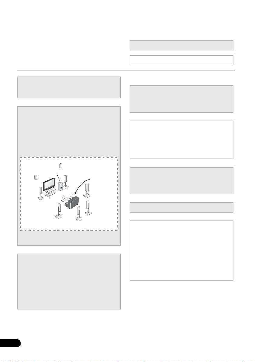
2
Connecting the speakers
Where you place the speakers will have a big
effect on the sound. Place your speakers as
5
The Pre Out Setting (page 42)
shown below for the best surround sound effect.
(When connecting the front height speakers.)
• Placing the speakers (page 16)
• Connecting the speakers (page 18)
The Input Assign menu (page 42)
• Connect the surround back or front height
(When using connections other than the
speakers (page 19)
recommended connections.)
*Front Height
Right (FHR)
*Front Height
Left (FHL)
Subwoofer (SW)
6
Use the automatic MCACC setup to set
Front
Listening
up your system
Right (R)
position
• Automatically setting up for surround sound
Surround
Front
Right (SR)
(MCACC) (page 27)
Left (L)
Center (C)
*Surround Back
7
Basic playback (page 29)
Right (SBR)
Surround
Left (SL)
*Surround Back
Left (SBL)
8
Adjusting the sound as desired
•Using the various listening modes
You can connect only one of either the surround back
• Using the Sound Retriever (page 33)
speaker or the front height speaker.
• Better sound using Phase Control (page 33)
• Using surround back channel processing
(page 34)
3
Connecting the components
• Setting the Up Mix function (page 35)
For surround sound, you’ll want to hook up
• Setting the Audio options (page 35)
using a digital connection from the BD/DVD
• Choosing the input signal (page 38)
player to the receiver.
• Manual speaker setup (page 39)
• About video outputs connection (page 21)
• Connecting a TV and playback components
(page 22)
• Connecting antennas (page 25)
• Plugging in the receiver (page 26)
6
En
Before you start 01
7
En
English
Français
Español
VSX-520_SYXCN_En.book 7 ページ 2010年4月12日 月曜日 午後7時13分
Chapter 1:
Before you start
• Batteries with the same shape may have
different voltages. Do not use different
Checking what’s in the box
batteries together.
Please check that you’ve received the following
• When disposing of used batteries, please
supplied accessories:
comply with governmental regulations or
• Setup microphone
environmental public instruction’s rules
• Remote control
that apply in your country or area.
• AAA size IEC R03 dry cell batteries (to
• Do not use or store batteries in direct
confirm system operation) x2
sunlight or other excessively hot place,
• AM loop antenna
such as inside a car or near a heater. This
can cause batteries to leak, overheat,
•FM wire antenna
explode or catch fire. It can also reduce the
•Power cord
life or performance of batteries.
• Warranty card
• These operating instructions
Installing the receiver
• When installing this unit, make sure to put
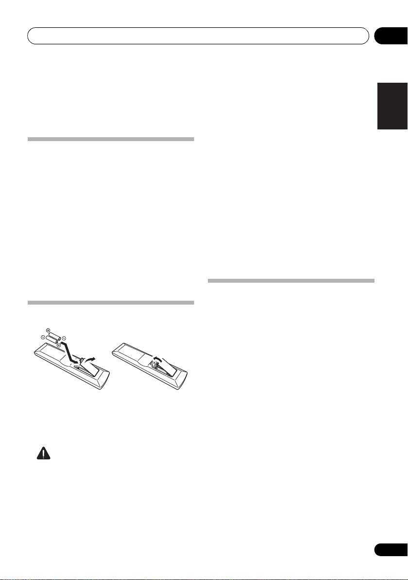
Loading the batteries
it on a level and stable surface.
Don’t install it on the following places:
– on a color TV (the screen may distort)
– near a cassette deck (or close to a device that
gives off a magnetic field). This may interfere
with the sound.
– in direct sunlight
– in damp or wet areas
– in extremely hot or cold areas
The batteries included with the unit are to
– in places where there is vibration or other
check initial operations; they may not last over
movement
a long period. We recommend using alkaline
– in places that are very dusty
batteries that have a longer life.
– in places that have hot fumes or oils (such as
a kitchen)
CAUTION
Incorrect use of batteries may result in such
hazards as leakage and bursting. Observe the
following precautions:
• Never use new and old batteries together.
• Insert the plus and minus sides of the
batteries properly according to the marks
in the battery case.
Before you start01
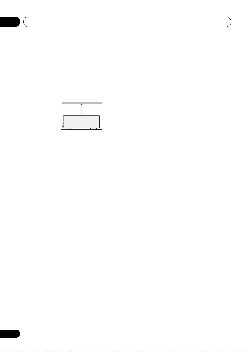
Ventilation
When installing this unit, make sure to leave
space around the unit for ventilation to improve
heat dispersal (at least 40 cm at the top). If not
enough space is provided between the unit and
walls or other equipment, heat will build up
inside, interfering with performance and/or
causing malfunctions.
Slot and openings in the cabinet are provided
for ventilation and to protect the equipment
from overheating. To prevent fire hazard, do not
place anything directly on top of the unit, make
sure the openings are never blocked or covered
with items (such as newspapers, table-cloths
and curtains), and do not operate the
equipment on thick carpet or a bed.
8
En
40 cm
Receiver
VSX-520_SYXCN_En.book 8 ページ 2010年4月12日 月曜日 午後7時13分
Controls and displays 02
9
En
English
Français
Español
Chapter 2:
Controls and displays
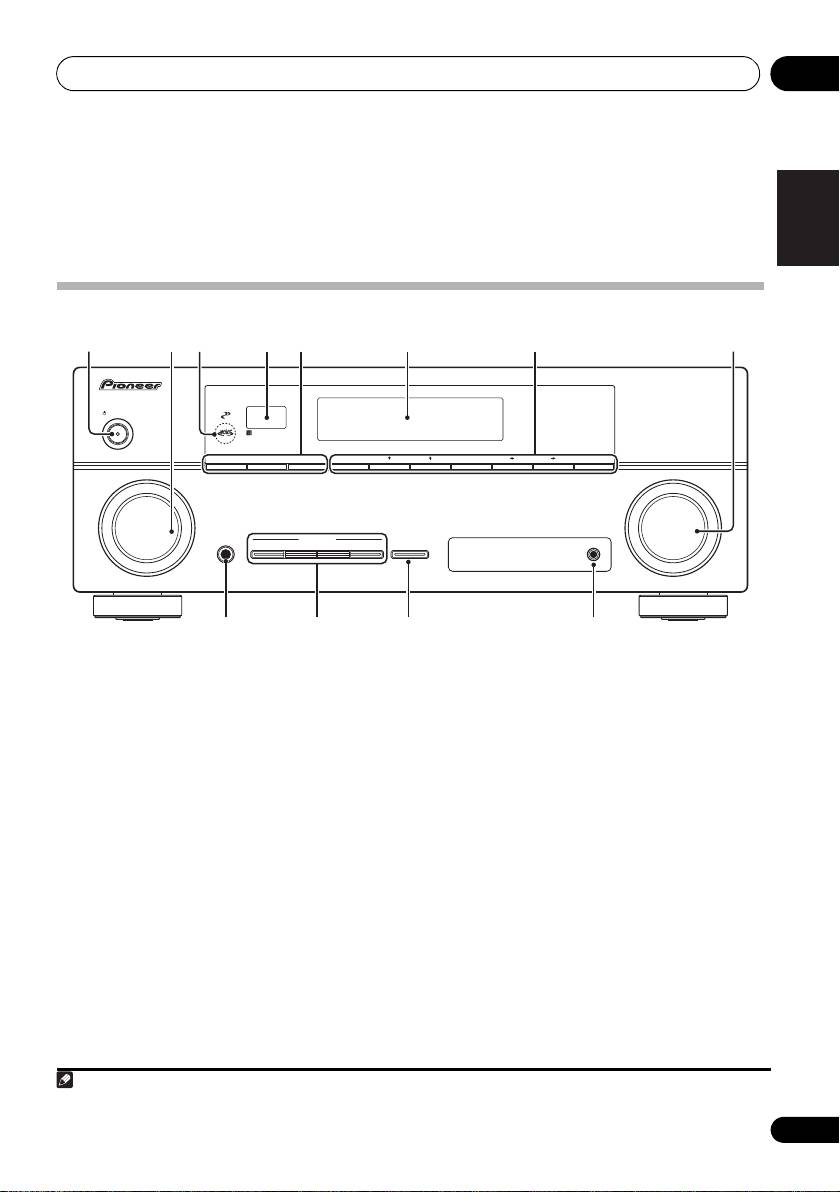
Front panel
1 27854 6
3
AUDIO/ VIDEO MULTI-CHANNEL RECEIVER
VSX
-520
CONTROL
PHASE
STANDBY/ON
SPEAKERS
DIMMER DISPLAY BAND TUNE TUNER EDIT PRESET ENTER
INPUT
MASTER
SELECTOR
VOLUME
PHONES
LISTENING MODE
AUTO/DIRECT STEREO/ ALC STANDARD
ADV SURROUND SOUND RETRIEVER
MCACC SETUP MIC
9 1110 12
1
STANDBY/ON
DIMMER
Dims or brightens the display. The
2
INPUT SELECTOR
dial
brightness can be controlled in four steps.
Selects an input source.
DISPLAY
3
MCACC
indicator
Switches the display of this unit. The
Lights when Acoustic Calibration EQ (page 34)
listening mode, sound volume, Pre Out
is on (Acoustic Calibration EQ is automatically
setting or input name can be checked by
set to on after the Auto MCACC Setup
1
selecting an input source.
(page 27)).
6 Character display
4 Remote sensor
See Display on page 11.
Receives the signals from the remote control
(see Operating range of remote control on
7 Tuner control buttons
page 10).
BAND
5
SPEAKERS
Switches between AM, FM ST (stereo) and
Use to change the speaker system on or
FM MONO radio bands (page 43).
off. When the SP OFF is selected, no sound
is output from the speakers connected to
TUNE /
this receiver.
Used to find radio frequencies (page 43).
Note
VSX-520_SYXCN_En.book 9 ページ 2010年4月12日 月曜日 午後7時13分
1 The Pre Out setting may or may not be displayed, depending on the input source you have selected.
Controls and displays02
TUNER EDIT
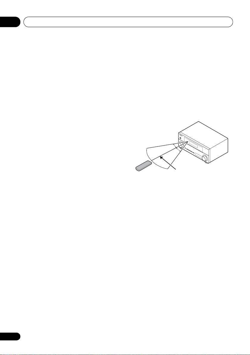
Operating range of remote control
Use with TUNE /, PRESET / and
The remote control may not work properly if:
ENTER to memorize and name stations for
• There are obstacles between the remote
recall (page 43, 44).
control and the receiver’s remote sensor.
PRESET /
• Direct sunlight or fluorescent light is
Use to select preset radio stations
shining onto the remote sensor.
(page 43).
• The receiver is located near a device that is
8
MASTER VOLUME
dial
emitting infrared rays.
9
PHONES
jack
• The receiver is operated simultaneously
Use to connect headphones. When the
with another infrared remote control unit.
headphones are connected, there is no sound
output from the speakers (page 38).
10 Listening mode buttons
AUTO/DIRECT
Switches between Auto surround mode
(Auto playback on page 30) and Stream
Direct playback. Stream Direct playback
bypasses the tone controls for the most
accurate reproduction of a source
(page 33).
STEREO/ALC
Switches between stereo playback, Auto
level control stereo mode (page 32) and
Front Stage Surround Advance modes
(page 32).
STANDARD
Press for Standard decoding and to switch
between the various 2 Pro Logic II, 2 Pro
Logic IIx, 2 Pro Logic IIz and NEO:6
options (page 30).
ADV SURROUND
Switches between the various surround
modes (page 31).
11
SOUND RETRIEVER
Press to restore CD quality sound to
compressed audio sources (page 33).
12
MCACC SETUP MIC
jack
Use to connect a microphone when
performing Auto MCACC setup.
10
En
30°
30°
7 m
VSX-520_SYXCN_En.book 10 ページ 2010年4月12日 月曜日 午後7時13分
Controls and displays 02
11
En
English
Français
Español
VSX-520_SYXCN_En.book 11 ページ 2010年4月12日 月曜日 午後7時13分
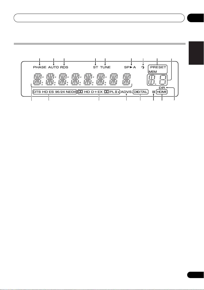
Display
1 2 3 4 5 6 7 8
9
10
11 12 13 14 14 1615
1PHASE
9 PRESET information or input signal
Lights when the Phase Control is switched on
indicator
(page 33).
Shows the preset number of the tuner or the
input signal type, etc.
2AUTO
Lights when the Auto Surround feature is
10 Character display
switched on (see Auto playback on page 30).
Displays various system information.
3RDS
11 DTS indicators
Lights when an RDS broadcast is received
DTS
(page 45).
Lights when a source with DTS encoded
4ST
audio signals is detected.
Lights when a stereo FM broadcast is being
HD
received in auto stereo mode.
Lights when a source with DTS-EXPRESS
5TUNE
or DTS-HD encoded audio signals is
Lights when a broadcast is being received.
detected.
6 Speaker indicator
ES
Shows if the speaker system is on or not
Lights to indicate DTS-ES decoding.
(page 9).
SP
A means the speakers are switched on.
96/24
Lights when a source with DTS 96/24
SP
means the speakers are switched off.
encoded audio signals is detected.
7 Sleep timer indicator
Lights when the receiver is in sleep mode
NEO:6
(page 13).
When one of the NEO:6 modes of the
receiver is on, this lights to indicate
8 Tuner preset indicators
NEO:6 processing (page 30).
PRESET
12 Dolby Digital indicators
Shows when a preset radio station is
registered or called.
2D
Lights when a Dolby Digital encoded signal
MEM
is detected.
Blinks when a radio station is registered.

VSX-520_SYXCN_En.book 12 ページ 2010年4月12日 月曜日 午後7時13分
Controls and displays02
2D+
Lights when a source with Dolby Digital
Plus encoded audio signals is detected.
2HD
Lights when a source with Dolby TrueHD
encoded audio signals is detected.
EX
Lights to indicate Dolby Digital EX
decoding.
2PLll(x)
Lights to indicate 2 Pro Logic II / 2 Pro
Logic IIx decoding. Light will go off during
2 Pro Logic IIz decoding (see Listening in
surround sound on page 30 for more on
this).
13 ADV.S.
Lights when one of the Advanced Surround
modes has been selected (see Using the
Advanced surround effects on page 31 for more
on this).
14 SIGNAL SELECT indicators
DIGITAL
Lights when a digital audio signal is
selected.
Blinks when a digital audio signal is
selected and if selected audio input is not
provided.
HDMI
Lights when an HDMI signal is selected.
Blinks when an HDMI signal is selected
and selected HDMI input is not provided.
15 Up Mix/DIMMER indicator
Lights when the Up Mix function is set to ON
(see page 35). Also, lights when DIMMER is set
to off.
16 DIR.
Lights when the DIRECT or PURE DIRECT
mode is switched on (page 33).
12
En
Controls and displays 02
13
En
English
Français
Español
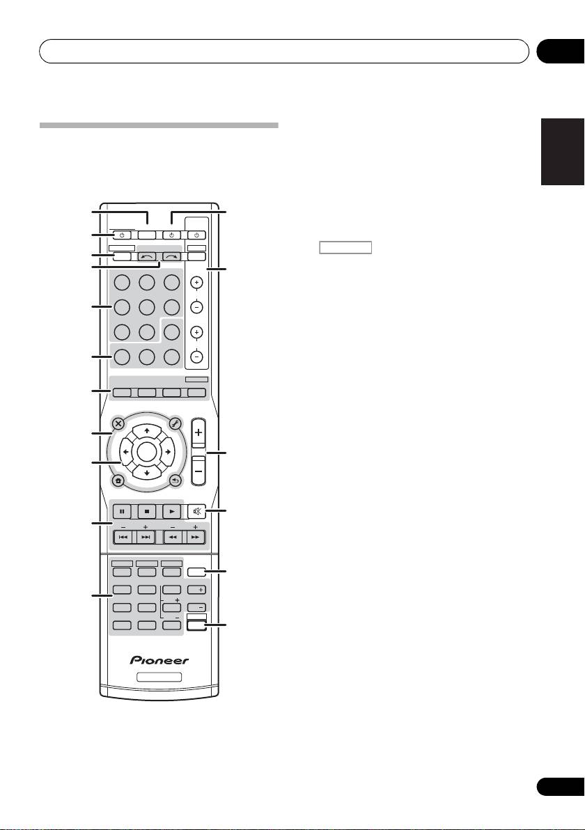
1
SLEEP
Press to change the amount of time
Remote control
before the receiver switches into standby (30
As for operating other devices, the remote
min – 60 min – 90 min – Off). You can check
control codes for the Pioneer products are
the remaining sleep time at any time by
preset. The settings cannot be changed.
pressing SLEEP once.
1
12
2
RECEIVER
TV
RECEIVER
SOURCESLEEP
CONTROL
Switches the receiver between standby and on.
2
RECEIVER
INPUT SELECT
DTV/TV
3
3
INPUT
Switches the remote to control the receiver
4
BD DVD
TV
13
(used to select the white commands above
the number buttons (MIDNIGHT, etc)). Also
DVR CD
CD-R
CH
use this button to set up surround sound
5
(page 39) or Audio parameters (page 35).
ADAPTER
TUNER
EQ
4 INPUT SELECT
PHASE
S.RETRIEVER SIGNAL SEL
VOL
Use to select the input source.
6
5 MULTI CONTROL buttons
AUTO/
STEREO/
BD MENU
DIRECT
A.L.C.
STANDARD
ADV SURR
Press to select control of other components.
7
6 Receiver control buttons
AUDIO
TUNER EDIT
MASTER
PARAMETER
TOOLS
VOLUME
MENU
TOP
T
U
N
E
MENU
EQ
8
T
P
Press to switch on/off Acoustic Calibration
E
R
S
E
E
ENTER
S
R
E
T
14
EQ setting (page 34).
P
9
HOME
PHASE
MENU
T
U
N
E
BAND
SETUP
RETURN
Press to switch on/off Phase Control
PTY SEARCH
MUTE
(page 33).
15
10
BASS
TRE
S. RETRIEVER
Press to restore CD quality sound to
compressed audio sources (page 33).
HDD
DVD
VCR
1
2
3
DISP
16
SIGNAL SEL
SB CH
CH SELECT
4
5
6
CH
Use to select an input signal (page 38).
11
MIDNIGHT
SPEAKERS
LEV
7
8
9
CH
7 Listening mode buttons
DIMMER
LEV
SHIFT
CLR
0
ENTER
17
+
10
AUTO/DIRECT
Switches between Auto surround mode
(Auto playback on page 30) and Stream
Direct playback. Stream Direct playback
RECEIVER
bypasses the tone controls for the most
accurate reproduction of a source
(page 33).
RECEIVER
VSX-520_SYXCN_En.book 13 ページ 2010年4月12日 月曜日 午後7時13分

Controls and displays02
STEREO/A.L.C.
Press TUNER first to access:
Switches between stereo playback, Auto
TUNER EDIT
level control stereo mode (page 32) and
Memorizes/names stations for recall
Front Stage Surround Advance modes
(page 43, 44).
(page 32).
PTY SEARCH
STANDARD
Use to search for RDS program types
Press for Standard decoding and to switch
(page 45).
between 2 Pro Logic II options (page 30).
BAND
ADV SURR
Switches between AM, FM ST (stereo) and
Switches between the various surround
FM MONO radio bands (page 43).
modes (page 31).
9
(
TUNE /
,
PRESET
/
),
Press BD first to access:
ENTER
BD MENU*
Use the arrow buttons when setting up your
Displays the disc menu of Blu-ray Discs.
surround sound system (page 39). Also used to
control BD/DVD menus/options.
8 System Setup and component control
buttons
Use the TUNE / buttons can be used to
The following button controls can be accessed
find radio frequencies (page 43) and the
after you have selected the corresponding
PRESET / buttons can be used to select
MULTI CONTROL button (BD, DVD, etc.).
preset radio stations (page 44).
Press first to access:
10 Component control buttons
The main buttons (, , etc.) are used to
AUDIO PARAMETER
control a component after you have selected it
Use to access the Audio options (page 35).
using the input source buttons.
SETUP
The controls above these buttons can be
Press to access the System Setup menu
accessed after you have selected the
(page 39).
corresponding input source button (BD, DVD,
DVR or CD). These buttons also function as
RETURN
described below.
Confirm and exit the current menu screen.
Press first to access:
Press BD, DVD or DVR first to access:
BASS –/+
TOP MENU
1
Use to adjust Bass
Displays the disc ‘top’ menu of a BD/DVD.
TRE –/+
HOME MENU
1
Use to adjust Treble
Displays the HOME MENU screen.
11 Number buttons and other component
RETURN
controls
Confirm and exit the current menu screen.
Use the number buttons to directly select the
tracks on a CD or tuner. There are other
MENU
buttons that can be accessed after the
Displays the TOOLS menu of Blu-ray Disc
button is pressed. (For example
player.
MIDNIGHT, etc.)
14
En
RECEIVER
Note
RECEIVER
1 The tone controls are disabled when the listening mode is set to DIRECT or PURE DIRECT.
RECEIVER
VSX-520_SYXCN_En.book 14 ページ 2010年4月12日 月曜日 午後7時13分

Controls and displays 02
15
En
English
Français
Español
HDD*, DVD*, VCR*
DTV/TV*
These buttons switch between the hard
Switches between the DTV and analog TV
disk, DVD and VCR controls for HDD/DVD/
input modes for Pioneer TVs.
VCR recorders.
14
MASTER VOLUME
+/–
SB CH
Use to set the listening volume.
Press to select ON, AUTO, OFF the
15
MUTE
surround back channel.
Mutes/unmutes the sound.
CH SELECT
16
DISP
Press repeatedly to select a channel, then
Switches the display of this unit. The listening
use LEV +/– to adjust the level (page 41).
mode, sound volume, Pre Out setting or input
name can be checked by selecting an input
LEV +/–
1
source.
Use to adjust the channel levels.
17
SHIFT
MIDNIGHT
Press to access the ‘boxed’ commands (above
Switches to Midnight or Loudness
the buttons) on the remote. These buttons are
listening (page 35).
marked with an asterisk (* ) in this section.
SPEAKERS
Use to change the speaker system on or
off. When the SP OFF is selected, no sound
is output from the speakers connected to
this receiver.
DIMMER
Dims or brightens the display. The
brightness can be controlled in four steps.
12
SOURCE
Turns on or off the power of the Pioneer DVD/
DVR units when BD, DVD, DVR or CD is
selected using the MULTI CONTROL buttons.
13
TV CONTROL
buttons
These buttons can control only be used with
Pioneer TVs.
Use to turn on/off the power of the TV.
INPUT
Use to select the TV input signal.
CH +/–
Use to select channels.
VOL +/–
Use to adjust the volume on your TV.
Note
VSX-520_SYXCN_En.book 15 ページ 2010年4月12日 月曜日 午後7時13分
1 The Pre Out setting may or may not be displayed, depending on the input source you have selected.
Connecting your equipment03
Chapter 3:
Connecting your equipment
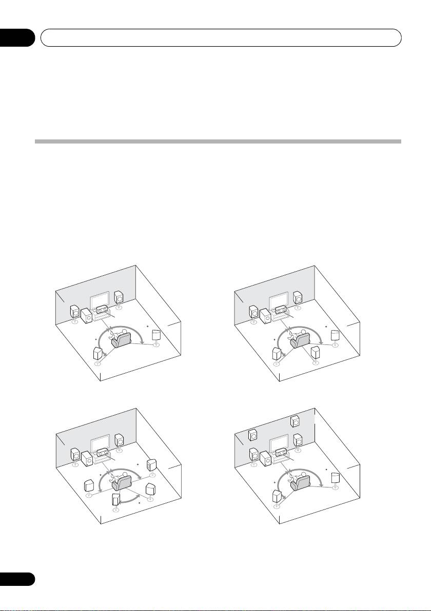
Placing the speakers
By connecting the left and right front speakers (L/R), the center speaker (C), the left and right
surround speakers (SL/SR), and the subwoofer (SW), a 5.1 ch surround system can be enjoyed.
Further, by using an external amplifier, you can connect the left and right surround back speakers
(
SBL
/
SBR
) and the left and right front height speaker (
FHL
/
FHR
) to boost your system up to a 7.1 ch
surround system.
• You can also connect one surround back speaker (SB) and enjoy a 6.1 ch surround system.
To achieve the best possible surround sound, install your speakers as shown below.
a. This layout is available only when the additional amplifier is connected to the unit and the surround back
or front height speakers are connected to the amplifier. For details, see Connect the surround back or front height
speakers on page 19.
16
En
R
R
L
L
C
C
SW
120
SW
120
120
120
SR
SR
SB
SL
SL
FHR
R
FHL
R
L
L
C
C
SR
90
SW
SW
120
90
120
SBR
SR
SL
60
SBL
SL
5.1 channel surround system:
6.1 channel surround
a
(Surround back) system:
7.1 channel surround
7.1 channel surround
a
a
(Surround back) system:
(Front height) system:
VSX-520_SYXCN_En.book 16 ページ 2010年4月12日 月曜日 午後7時13分

Connecting your equipment 03
17
En
English
Français
Español
VSX-520_SYXCN_En.book 17 ページ 2010年4月12日 月曜日 午後7時13分
Hints on the speaker placement
• Try not to place the surround speakers
farther away from the listening position
Where you put your speakers in the room has a
than the front and center speakers. Doing
big effect on the quality of the sound. The
so can weaken the surround sound effect.
following guidelines should help you to get the
best sound from your system.
• Place the left and right front height
speakers at least one meter directly above
• The subwoofer can be placed on the floor.
the left and right front speakers.
Ideally, the other speakers should be at
about ear-level when you’re listening to
them. Putting the speakers on the floor
CAUTION
(except the subwoofer), or mounting them
very high on a wall is not recommended.
• Make sure that all speakers are securely
installed. This not only improves sound
• For the best stereo effect, place the front
quality, but also reduces the risk of
speakers 2 m to 3 m apart, at equal
damage or injury resulting from speakers
distance from the TV.
being knocked over or falling in the event
• If you’re going to place speakers around
of external shocks such as earthquakes.
your CRT TV, use shielded speakers or
place the speakers at a sufficient distance
from your CRT TV.
Important
• If you’re using a center speaker, place the
• To connect the surround back or front
front speakers at a wider angle. If not, place
height speakers, an additional amplifier is
them at a narrower angle.
required. Connect the additional amplifier
to the PRE OUT SURR BACK/FRONT
• Place the center speaker above or below
HEIGHT outputs of this unit and connect
the TV so that the sound of the center
the surround back or front height speakers
channel is localized at the TV screen. Also,
to the additional amplifier (see Connect the
make sure the center speaker does not
surround back or front height speakers on
cross the line formed by the leading edge
page 19).
of the front left and right speakers.
The Pre Out setting must be set if the above
• It is best to angle the speakers towards the
connections are performed. Select
listening position. The angle depends on
SURR.BACK if the surround back speaker
the size of the room. Use less of an angle
is connected and HEIGHT if the front
for bigger rooms.
height speaker is connected (If neither the
• Surround and surround back speakers
surround back speaker nor the front height
should be positioned 60 cm to 90 cm higher
speaker is connected, either setting will
than your ears and titled slight downward.
suffice) (see The Pre Out Setting on
Make sure the speakers don’t face each
page 42).
other. For DVD-Audio, the speakers should
be more directly behind the listener than for
home theater playback.
• If the surround speakers cannot be set
directly to the side of the listening position
with a 7.1-channel system, the surround
effect can be enhanced by turning off the
Up Mix function (see Setting the Up Mix
function on page 35).
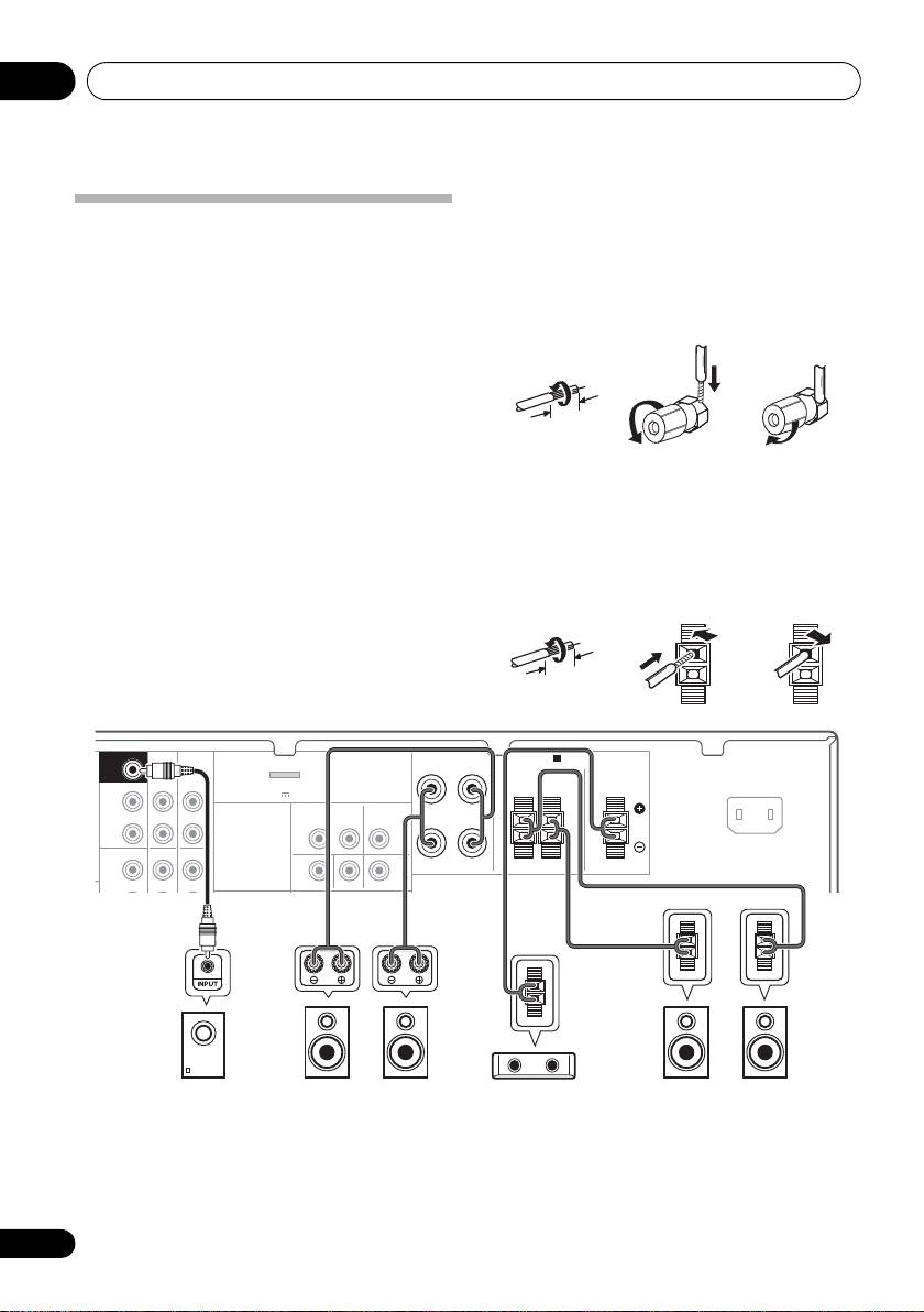
Connecting your equipment03
Bare wire connections
Front speaker terminals:
Connecting the speakers
The receiver will work with just two stereo
1 Twist exposed wire strands together.
speakers (the front speakers in the diagram)
2 Loosen terminal and insert exposed wire.
but using at least three speakers is
recommended, and a complete setup is best
3 Tighten terminal.
for surround sound.
Make sure you connect the speaker on the
123
right to the right (R) terminal and the speaker
on the left to the left (L) terminal. Also make
sure the positive and negative (+/–) terminals
on the receiver match those on the speakers.
Center and surround speaker terminals:
If you’re not using a subwoofer, change the
front speaker setting (see Speaker setting on
1 Twist exposed wire strands together.
page 40) to LARGE.
2 Push open the tabs and insert exposed
Be sure to complete all connections before
wire.
connecting this unit to the AC power source.
3 Release the tabs.
18
En
10 mm
12 3
10 mm
FRONT
RL
CD-R/TAPE
DVR/VCR
SURROUND CENTER
SURR BACK /
FRONT
RL
HEIGHT
L
(
Single
)
OUT
R
PRE OUT
CD
CD-R/TAPE
DVR/VCR
L
IN IN
MONITOR OUT
DVD IN BD IN
E
SUBWOOFER
PRE OUT
SPEAKERS
A
ADAPTER PORT
AC IN
(
OUTPUT 5 V 100 mA MAX
)
VIDEO
DVR/VCR
TV/SAT
OUT IN
IN
SW
L
RSLSR
C
Powered subwoofer
Center speaker
Surround speakersFront speakers
VSX-520_SYXCN_En.book 18 ページ 2010年4月12日 月曜日 午後7時13分
Connecting your equipment 03
19
En
English
Français
Español
CAUTION
Making cable connections
• These speaker terminals carry
Make sure not to bend the cables over the top
HAZARDOUS LIVE voltage. To prevent
of this unit (as shown in the illustration). If this
the risk of electric shock when connecting
happens, the magnetic field produced by the
or disconnecting the speaker cables,
transformers in this unit may cause a
disconnect the power cord before touching
humming noise from the speakers.
any uninsulated parts.
• Make sure that all the bare speaker wire is
twisted together and inserted fully into the
speaker terminal. If any of the bare speaker
wire touches the back panel it may cause
the power to cut off as a safety measure.
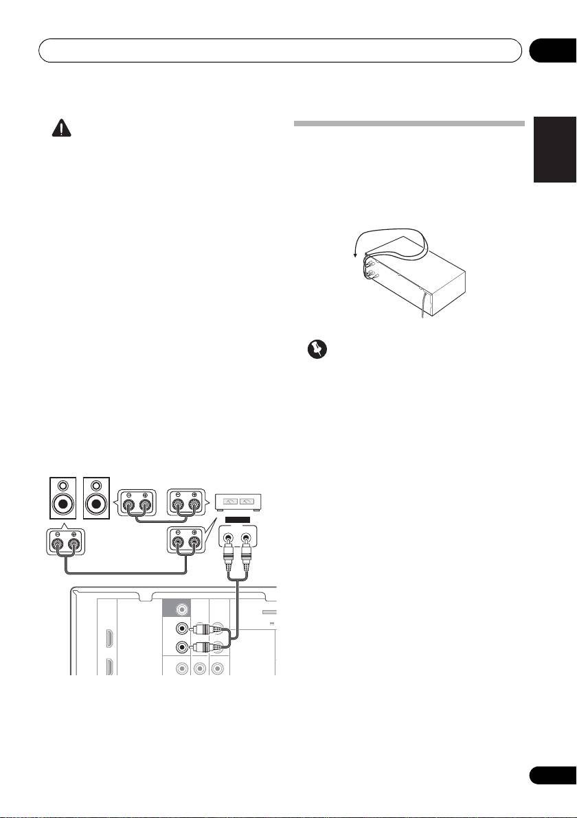
Connect the surround back or front
height speakers
Connect the PRE OUT outputs of the unit and
Important
additional amplifier to add a surround back or
front height speaker.
• Before making or changing connections,
switch off the power and disconnect the
• If the surround back speaker or the front
power cord from the AC outlet.
height speaker is connected, set the Pre
Out setting (see The Pre Out Setting on
• Before unplugging the power cord, switch
page 42).
the power into standby.
• You can use the additional amplifier on the
surround back channel pre-outs for a
single speaker as well. In this case plug the
amplifier into the left (L (Single)) terminal
only.
SUBWOOFER
PRE OUT
CD-R/TAPE
DVR/VCR
SURR BACK /
ADAPTER
FRONT
(
BD
HEIGHT
OUTPUT 5 V 1
L
(
Single
)
OUT
R
DVD
PRE OUT
CD
CD-R/TAPE
DVR/VCR
L
SBL/FHL SBR/FHR
ANALOG
INPUT
LR
Surround back or
front height speakers
Surround back or
front height
channel amplifier
VSX-520_SYXCN_En.book 19 ページ 2010年4月12日 月曜日 午後7時13分
Connecting your equipment03
HDMI cables
• Input of multi-channel linear PCM digital
audio signals (192 kHz or less) for up to 8
Both video and sound signals can be transmitted
channels
simultaneously with one cable. If connecting the
player and the TV via this receiver, for both
4
•
Input of the following digital audio formats:
1
connections, use HDMI cables.
– Dolby Digital, Dolby Digital Plus, DTS,
High bitrate audio (Dolby TrueHD, DTS-HD
Master Audio), DVD-Audio, CD, SACD
(DSD signal), Video CD, Super VCD
HDMI, the HDMI Logo and High-Definition
Multimedia Interface are trademarks or
registered trademarks of HDMI Licensing, LLC in
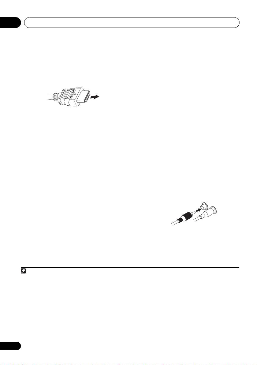
Be careful to connect the terminal in the
the United States and other countries.
proper direction.
“x.v.Color” and x.v.Color logo are trademarks of
About HDMI
Sony Corporation.
The HDMI connection transfers
uncompressed digital video, as well as almost
Analog audio cables
every kind of digital audio that the connected
Use stereo RCA phono cables to connect
component is compatible with, including DVD-
analog audio components. These cables are
Video, DVD-Audio, SACD, Dolby Digital Plus,
typically red and white, and you should
Dolby TrueHD, DTS-HD Master Audio (see
connect the red plugs to R (right) terminals
below for limitations), Video CD/Super VCD
and white plugs to L (left) terminals.
and CD.
This receiver incorporates High-Definition
®
Multimedia Interface (HDMI
) technology.
This receiver supports the functions described
2
below through HDMI connections.
• Digital transfer of uncompressed video
(contents protected by HDCP (1080p/24,
1080p/60, etc.))
3
• 3D signal transfer
3
• Deep Color signal transfer
3
• x.v.Color signal transfer
20
En
Note
1 • Set the HDMI parameter in Setting the Audio options on page 35 to THRU (THROUGH) and set the input signal in Choosing
the input signal on page 38 to HDMI, if you want to hear HDMI audio output from your TV (no sound will be heard from this
receiver).
• If the video signal does not appear on your TV, try adjusting the resolution settings on your component or display. Note that
some components (such as video game units) have resolutions that may not be displayed. In this case, use a (analog)
composite connection.
• When the video signal from the HDMI is 480i, 480p, 576i or 576p, Multi Ch PCM sound and HD sound cannot be received.
®
®
2 • Use a High Speed HDMI
cable. If HDMI cable other than a High Speed HDMI
cable is used, it may not work properly.
• When an HDMI cable with a built-in equalizer is connected, it may not operate properly.
3 Signal transfer is only possible when connected to a compatible component.
HDMI cable
VSX-520_SYXCN_En.book 20 ページ 2010年4月12日 月曜日 午後7時13分
Analog audio cables
Right (red)
Left (white)
4 • HDMI format digital audio transmissions require a longer time to be recognized. Due to this, interruption in the audio may
occur when switching between audio formats or beginning playback.
• Turning on/off the device connected to this unit's HDMI OUT terminal during playback, or disconnecting/connecting the
HDMI cable during playback, may cause noise or interrupted audio.
