Pioneer DEH-9300SD: instruction
Class: Auto, Moto equipment and Transportation
Type:


Manual for Pioneer DEH-9300SD

<QRD3072-A> <>
<KOKZX> <10I00000>
Printed in Thailand
Imprimé en Thaïlande
<
QRD3072-A/N
> EW
Installation Manual
Manuel d’installation
Manuale d’installazione
Manual de instalación
Installationsanleitung
Installatiehandleiding
Руководство по установке
CD RDS RECEIVER
AUTORADIO CD RDS
SINTOLETTORE CD RDS
REPRODUCTOR DE CD CON RECEPTOR RDS
CD RDS-EMPFÄNGER
CD RDS-ONTVANGER
CD RDS ПРИЕМНИК
DEH-9300SD
<QRD3072-A> <2>
Installation English Installation English
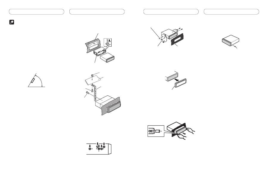
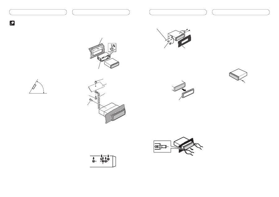
2. Tighten two screws on each side.
Dashboard or Console
Mounting bracket
Tapping screw (5 mm × 8 mm)
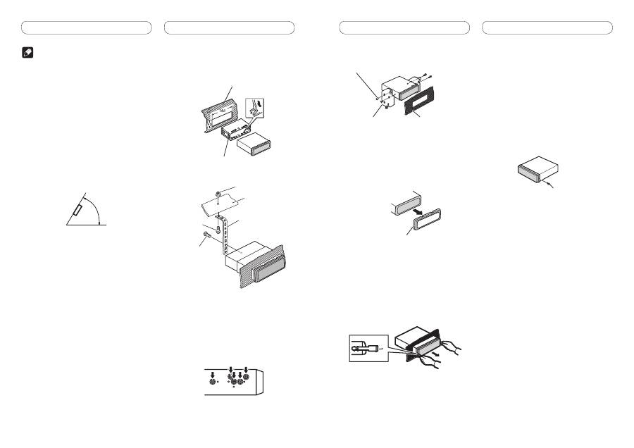
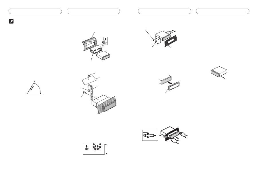
Removing the unit
1. Extend top and bottom of the trim
ring outwards to remove the trim
ring. (When reattaching the trim ring,
point the side with the groove down.)
Trim ring
• Releasing the front panel allows easier access
to the trim ring.
2. Insert the supplied extraction keys
into both sides of the unit until they
click into place.
3. Pull the unit out of the dashboard.
Removing and re-attaching the
front panel
You can remove the front panel to protect your
unit from theft.
Press the detach button and push the front
panel upward and pull it toward you.
For details, refer to operation manual.
Fastening the front panel
If you do not plan to detach the front panel,
the front panel can be fastened with supplied
screw.
Screw
Note
•
Check all connections and systems before final
installation.
•
Do not use unauthorized parts. The use of
unauthorized parts may cause malfunctions.
•
Consult with your dealer if installation requires
drilling of holes or other modifications of the
vehicle.
•
Do not install this unit where:
—
it may interfere with operation of the vehicle.
—
it may cause injury to a passenger as a result
of a sudden stop.
•
The semiconductor laser will be damaged if it
overheats. Install this unit away from hot places
such as near the heater outlet.
•
Optimum performance is obtained when the unit is
installed at an angle of less than 60°.
60°
DIN front/rear-mount
This unit can be properly installed either from
“Front” (conventional DIN Front-mount) or
“Rear” (DIN Rear-mount installation, utilizing
threaded screw holes at the sides of unit
chassis). For details, refer to the following
installation methods.
• Use commercially available parts when
installing.
DIN Front-mount
1. Insert the mounting sleeve into the
dashboard.
For installation in shallow spaces, use the
supplied mounting sleeve. If there is enough
space, use the mounting sleeve that came with
the vehicle.
2. Secure the mounting sleeve by using
a screwdriver to bend the metal tabs
(90°) into place.
Dashboard
Mounting sleeve
3. Install the unit as illustrated.
Screw (M4
×
8)
Screw
Metal strap
Nut
Firewall or
metal support
• Make sure that the unit is installed securely
in place. An unstable installation may cause
skipping or other malfunctions.
DIN Rear-mount
1. Determine the appropriate position
where the holes on the bracket and
the side of the unit match.

<QRD3072-A> <3>
Installation Français
2. Serrez deux vis de chaque côté.
Tableau de bord ou
console
Support de montage
Vis taraudeuse (5 mm × 8 mm)
Enlèvement de l’appareil
1. Étirez le haut et le bas de l’anneau de
garniture vers l’extérieur pour retirer
la garniture. (Quand vous remontez
l’anneau de garniture, pointez le côté
avec la rainure vers le bas.)
Anneau de garniture
• Relâcher la face avant permet d’accéder plus
facilement à l’anneau de garniture.
2. Insérez les clés d’extraction fournies
dans les deux côtés de l’appareil
jusqu’à ce qu’elles s’enclenchent en
place.
3. Tirez l’appareil hors du tableau de
bord.
Retrait et remontage de la face
avant
Vous pouvez retirer la face avant pour protéger
l’appareil contre le vol.
Appuyez sur la touche de retrait, puis poussez
la face avant vers le haut et tirez-la vers vous.
Pour plus de détails, reportez-vous au mode
d’emploi.
Fixation du panneau avant
Si vous ne prévoyez pas de détacher le
panneau avant, il peut être fixé avec la vis
fournie.
Vis
Installation Français
Remarque
• Vérifiez toutes les connexions et tous les
systèmes avant l’installation finale.
• N’utilisez aucune pièce non autorisée. L’utilisation
de pièces non autorisées peut causer un mauvais
fonctionnement.
• Consultez votre revendeur si l’installation
nécessite que vous perciez des trous ou effectuiez
d’autres modifications du véhicule.
• N’installez pas l’appareil dans un endroit où:
— il peut gêner la conduite du véhicule.
— il peut causer des blessures à un passager à
la suite d’un arrêt brutal.
• Le laser à semi-conducteur sera endommagé en
cas de surchauffe. Installez cet appareil à l’écart
des endroits chauds tels que près de la sortie du
chauffage.
• Des performances optimales peuvent être
obtenues quand l’appareil est installé avec un
angle de moins de 60°.
60°
Montage avant/arrière DIN
Cet appareil peut être installé correctement
par “l’avant” (montage avant conventionnel
DIN) ou par “l’arrière” (montage par l’arrière
DIN, en utilisant les trous taraudés de chaque
côté du châssis de l’appareil). Pour les détails,
reportez-vous aux méthodes d’installation
suivantes.
• Utilisez des pièces disponibles dans le
commerce lors de l’installation.
Montage frontal DIN
1. Insérez le manchon de montage dans
le tableau de bord.
Lors de l’installation de cet appareil dans un
espace peu profond, utilisez le manchon de
montage fourni. Si l’espace est suffisant,
utilisez le manchon de montage fourni avec le
véhicule.
2. Fixez le manchon de montage en
utilisant un tournevis pour courber
les pattes métalliques (90°) en place.
Tableau de bord
Manchon de montage
3. Installez l’appareil comme indiqué
sur la figure.
Vis (M4
×
8)
Vis
Attache en métal
Écrou
Pare-feu ou support
métallique
• Assurez-vous que l’appareil est correctement
mis en place. Toute installation instable
peut entraîner des sauts ou autres
dysfonctionnements.
Montage arrière DIN
1. Déterminez la position appropriée où
les trous sur le support et sur le côté
de l’appareil se correspondent.

<QRD3072-A> <>
Installazione Italiano Installazione Italiano
Nota
• Prima dell’installazione finale vi raccomandiamo
di verificare tutti i sistemi coinvolti e le relative
connessioni.
• Non fate mai uso di parti non autorizzate. Esse
potrebbero infatti dar luogo a malfunzionamenti.
• Qualora l’installazione richieda l’esecuzione di fori
oppure di modifiche al veicolo, rivolgetevi innanzi
tutto al vostro rivenditore.
• Non installate questa unità ove:
— possa interferire con la guida del veicolo.
— possa causare il ferimento dei passeggeri in
caso di brusca frenata.
• Il laser a semiconduttore si potrebbe danneggiare
in caso di surriscaldamento. Installate pertanto
l’unità lontano dai punti ad elevata temperatura
quali, ad esempio, gli effusori del sistema di
riscaldamento del veicolo.
• Le prestazioni migliori si ottengono quando
s’installa l’unità secondo un angolo di ampiezza
inferiore a 60°.
60°
Installazione DIN frontale/ posteriore
L’unità può essere correttamente installata sia
“frontalmente” (normale installazione DIN
frontale) sia “posteriormente” (installazione
DIN posteriore impiegando i fori filettati ubicati
sui lati del telaio). Le sezioni che seguono
offrono informazioni dettagliate sui due
metodi d’installazione.
• Durante l’installazione utilizzare componenti
disponibili in commercio.
Montaggio DIN frontale
1. Inserire il supporto di montaggio nel
cruscotto.
Se l’unità viene installata in uno spazio poco
profondo, utilizzare il supporto di montaggio
fornito in dotazione. Se dietro l’unità vi è
spazio sufficiente, utilizzare il supporto di
montaggio già predisposto con il veicolo.
2. Assicurare il supporto di montaggio
utilizzando un cacciavite per piegare
le linguette metalliche (90°) in
posizione.
Cruscotto
Supporto di montaggio
3. Installare l’unità come illustrato.
Vite (M4
×
8)
Vite
Striscia metallica
Dado
Protezione
antifiamma o
supporto metallico
• Accertarsi che l’unità sia installata
saldamente in posizione. Un’installazione
instabile potrebbe causare salti audio o altri
malfunzionamenti.
Montaggio DIN posteriore
1. Determinare la posizione appropriata,
in modo che i fori sulla staffa e sul
lato dell’unità corrispondano.
2. Serrare con due viti su ciascun lato.
Cruscotto o console
Staffa di montaggio
Vite autofilettante (5 mm × 8 mm)
Rimozione dell’unità
1. Estendere verso l’esterno la
parte superiore e inferiore della
guarnizione per rimuoverla. (Quando
si riapplica la guarnizione, orientare
verso il basso il lato provvisto di
scanalatura.)
Guarnizione
• La rimozione del pannello anteriore permette
di accedere facilmente alla guarnizione.
2. Inserire le chiavi di estrazione,
fornite in dotazione, in entrambi i lati
dell’unità fino a che non scattano in
posizione.
3. Estrarre l’unità dal cruscotto.
Rimozione e reinserimento del
frontalino
È possibile rimuovere il frontalino per
proteggere l’unità dai furti.
Premere il tasto di rimozione e spingere il
frontalino verso l’alto tirandolo verso l’esterno.
Per ulteriori dettagli, vedere il manuale
d’istruzioni.
Fissaggio del pannello anteriore
Qualora non intendiate separare il pannello
anteriore, esso può essere perennemente
fissato con la vite fornita in dotazione.
Vite
<QRD3072-A> <>
Instalación Español
2. Apriete los dos tornillos en cada lado.
Salpicadero o consola
Soporte de montaje
Tornillo con rosca cortante (5 mm × 8 mm)
Retirada de la unidad
1. Extienda hacia afuera la parte
superior e inferior del anillo de
guarnición para retirarlo. (Al volver
a colocar el anillo de guarnición,
oriente el lado que tiene una ranura
hacia abajo.)
Anillo de guarnición
• Libere el panel delantero para acceder más
fácilmente al anillo de guarnición.
2. Inserte en ambos lados de la unidad
las llaves de extracción provistas
hasta que se escuche un ligero
chasquido.
3. Extraiga la unidad del salpicadero.
Retirada y colocación del panel
delantero
Puede extraer el panel delantero para proteger
la unidad contra robo.
Pulse el botón de soltar, empuje el panel
delantero hacia arriba y tire de él hacia sí.
Si desea más información, consulte el manual
de instrucciones.
Fijación del panel delantero
Si no planea extraer el panel delantero, se
puede fijar el panel delantero con el tornillo
suministrado.
Tornillo
Instalación Español
Nota
• Verifique todas las conexiones y sistemas antes de
la instalación final.
• No utilice piezas no autorizadas. El uso de piezas
no autorizadas puede causar un fallo de
funcionamiento.
• Consulte su revendedor si se requiere taladrar
agujeros o hacer otras modificaciones del
vehículo para la instalación.
• No instale esta unidad donde:
— pu
eda interferir con la operación del vehículo.
— pueda causar lesiones a un pasajero en el caso
de un
a parada brusca.
• El láser semiconductor se dañará si se
sobrecalienta. Instale esta unidad alejada de
lugares calientes como cerca de la salida del
calentador.
• Se obtiene el rendimiento óptimo cuando se instala
la u
nidad en un ángulo inferior a 60°.
60
°
Montaje delantero/trasero DIN
Se puede instalar esta unidad apropiadamente
mediante el montaje “delantero” (montaje
delantero DIN convencional) o montaje
“trasero” (montaje trasero DIN utilizando
los agujeros de tornillo roscados en los lados
del bastidor de la unidad). Para los detalles,
consulte los siguientes métodos de instalación.
• En la instalación, emplee piezas disponibles
en el mercado.
Montaje delantero DIN
1. Inserte el manguito de montaje en el
salpicadero.
Si realiza la instalación en un espacio poco
profundo, utilice el manguito de montaje
suministrado. Si hay suficiente espacio, utilice
el manguito de montaje que viene con el
vehículo.
2. Fije el manguito de montaje
utilizando un destornillador para
doblar las pestañas metálicas (90°) y
colocarlas en su lugar.
Salpicadero
Manguito de montaje
3. Instale la unidad según la ilustración.
Tornillo (M4
×
8)
Tornillo
Correa metálica
Tuerca
Muro cortafuego o
soporte de metal
• Asegúrese de que la unidad esté firmemente
instalada en su lugar. Una instalación
inestable puede causar saltos en el audio o un
mal funcionamiento de la unidad.
Montaje trasero DIN
1. Determine la posición correcta, de
modo que los agujeros del soporte y
del lateral de la unidad coincidan.
<QRD3072-A> <>
Einbau Deutsch Einbau Deutsch
Hinweise
• Überprüfen Sie alle Anschlüsse und Systeme,
bevor Sie das Gerät endgültig einbauen.
• Verwenden Sie keine unautorisierten Teile. Die
Verwendung von unautorisierten Teilen kann zu
Funktionsstörungen führen.
• Wenden Sie sich an Ihren Fachhändler, wenn zum
Einbau des Geräts Löcher gebohrt oder andere
Veränderungen an Ihrem Auto
vorgenommen wenden müssen.
• Bauen Sie das Gerät nicht an einer Stelle ein, wo:
— es den Fahrer beim Fahren behindert.
— es den Beifahrer bei plötzlichem Bremsen
verletzen kann.
• Der Halbleiterlaser wird bei Überhitzung
beschädigt. Bauen Sie das Gerät daher nicht an
einer Stelle ein, wo es heiß wird, z. B. in der Nähe
einer Heizungsauslassöffnung.
• Die optimale Leistung wird erzielt, wenn der
Einbauwinkel nicht mehr als 60° beträgt.
60°
DIN-Front-/Rückmontage
Dieses Gerät kann entweder an der
“Vorderseite” (herkömmlicher DIN Einbau an
der Vorderseite) oder an der “Rückseite” (DIN
Einbau an der Rückseite mit Hilfe der Löcher
für die Gewindeschrauben, die sich an der
Seite des Geräte-Chassis befinden) eingebaut
werden. Einzelheiten entnehmen Sie bitte den
folgenden Einbaumethoden.
• Verwenden Sie für die Montage im Handel
erhältliches Zubehör.
DIN-Frontmontage
1. Führen Sie den Montagerahmen in
das Armaturenbrett ein.
Verwenden Sie den mitgelieferten
Montagerahmen, wenn bei der Installation
wenig Platz zur Verfügung steht. Bei
ausreichendem Platz kann der mit dem
Fahrzeug mitgelieferte Montagerahmen
verwendet werden.
2. Befestigen Sie den Montagerahmen
mithilfe eines Schraubendrehers: Die
Metallklammern sind in eine sichere
Position (90°) zu biegen.
Armaturenbrett
Montagerahmen
3. Installieren Sie das Gerät wie in der
Abbildung gezeigt.
Schraube (M4
×
8)
Schraube
Metallbügel
Mutter
Firewall oder
Metallstütze
• Stellen Sie sicher, dass das Gerät fest
angebracht ist. Ein instabiler Einbau kann
zum Aussetzen von Tönen führen oder andere
Funktionsstörungen verursachen.
DIN-Rückmontage
1. Bestimmen Sie die geeignete
Position, damit die Löcher an der
Klammer und den Geräteseiten
ordnungsgemäß ausgerichtet sind.
2. Ziehen Sie auf jeder Seite zwei
Schrauben fest.
Armaturenbrett oder
Konsole
Montageklammer
Blechschraube (5 mm × 8 mm)
Entfernen des Geräts
1. Ziehen Sie den Einpassungsring oben
und unten nach außen, um ihn zu
entfernen. (Um den Einpassungsring
wieder anzubringen, drücken Sie die
Seite mit der Nute nach unten.)
Einpassungsring
• Bei entriegelter Bedienfläche lässt sich der
Einpassungsring einfacher erreichen.
2. Führen Sie die mitgelieferten
Extraktionsschlüssel an beiden
Geräteseiten ein, bis sie in der
richtigen Position einrasten.
3. Ziehen Sie das Gerät aus dem
Armaturenbrett.
Abnehmen und
Wiederanbringen der Frontplatte
Sie können die Frontplatte zum Schutz vor
Diebstahl abnehmen.
Drücken Sie die Taste zum Entriegeln der
Frontplatte und schieben Sie sie nach oben und
auf Sie zu.
Details finden Sie in der Bedienungsanleitung.
Befestigung der Frontplatte
Falls Sie nicht beabsichtigen, die Frontplatte
abzunehmen, kann sie mit der mitgelieferten
Schraube befestigt werden.
Schraube
<QRD3072-A> <7>
Installatie Nederlands
2. Draai aan elke kant twee schroeven
vast.
Dashboard of console
Bevestigingsbeugel
Zelftappende schroef (5 mm × 8 mm)
Het toestel verwijderen
1. Verwijder de sierlijst door deze aan
de boven- en onderkant naar buiten
te trekken. (Als u de sierlijst weer
bevestigt, houdt u de kant met de
groef naar onderen.)
Sierlijst
• De sierlijst is gemakkelijker bereikbaar als u
het voorpaneel verwijdert.
2. Steek de meegeleverde
uittreksleutels in de beide kanten van
het toestel totdat ze op hun plaats
klikken.
3. Trek het toestel uit het dashboard.
Het voorpaneel verwijderen en
terug bevestigen
U kunt het voorpaneel verwijderen om het
toestel tegen diefstal te beveiligen.
Druk op de knop om het voorpaneel los te
maken, duw het naar boven en trek het naar
u toe.
Raadpleeg de handleiding voor meer
informatie.
Vastzetten van het voorpaneel
Als u het voorpaneel niet wilt kunnen
verwijderen, kunt u het vastzetten met de
daartoe meegeleverde schroef.
Schroef
Installatie Nederlands
Opmerking
• Controleer alle aansluitingen en systemen voor de
uiteindelijke installatie.
• Gebruik geen ongeautoriseerde onderdelen.
Gebruik van niet-goedgekeurde onderdelen kan
leiden tot storingen.
• Raadpleeg uw dealer als u voor de installatie
gaten moet boren of andere wijzigingen aan het
voertuig zelf moet aanbrengen.
• Installeer dit toestel in geen geval op een locatie
waar:
— het de besturing van het voertuig kan
hinderen.
— het een passagier zou kunnen verwonden bij
een noodstop.
• De halfgeleider laser zal kapot gaan als deze
oververhit raakt. Installeer dit toestel niet in de
buurt van zeer warme plekken, zoals bij een
verwarmingsrooster.
• De optimale prestaties worden verkregen wanneer
het toestel geïnstalleerd wordt onder een hoek van
minder dan 60º.
60°
DIN Voor/achter montage
Dit toestel kan op de juiste manier worden
vastgemaakt aan de voorkant (conventionele
DIN montage) of aan de achterkant
(DIN achtermontage, met behulp van de
schroefgaatjes aan de zijkanten van het chassis
van het toestel). Voor details verwijzen we u
naar de volgende installatiemethoden.
• Gebruik voor installatie in de handel
verkrijgbare onderdelen.
DIN-voormontage
1. Schuif de montagebehuizing in het
dashboard.
Gebruik voor installatie in een ondiepe
ruimte de meegeleverde montagebehuizing.
Als er voldoende ruimte is, gebruikt u de
montagebehuizing die met het voertuig
geleverd werd.
2. Zet de montagebehuizing vast door
met een schroevendraaier de metalen
lipjes op hun plaats te buigen (90°).
Dashboard
Montagebehuizing
3. Installeer het toestel zoals
aangegeven.
Schroef (M4
×
8)
Schroef
Metalen strip
Moer
Brandschot of
metalen steun
• Controleer of het toestel stevig op zijn plaats
is gemonteerd. Het toestel functioneert
wellicht niet naar behoren als het niet goed is
bevestigd.
DIN-achtermontage
1. Bepaal de juiste positie waar de
gaten in de beugel en in de zijde van
het toestel op een lijn liggen.
<QRD3072-A> <>
Установка Pycckий Установка Pycckий
Примечание
• Проверьте все соединения и системы перед
окончательной установкой.
• Не используйте неразрешенные детали.
Использование неразрешенных деталей может
стать причиной неисправной работы.
• Проконсультируйтесь с вашим дилером, если
установка требует просверливания отверстий
или других модификаций вашего транспортного
средства.
• Не устанавливайте устройство там, где:
— оно может служить препятствием работы
транспортного средства.
— оно может стать причиной ранения
пассажира в результате внезапной
остановки.
• Полупроводниковый лазер будет поврежден,
если он перегреется. Устанавливайте данное
устройство вдали от горячих мест, таких как
рядом с выпуском нагревателя.
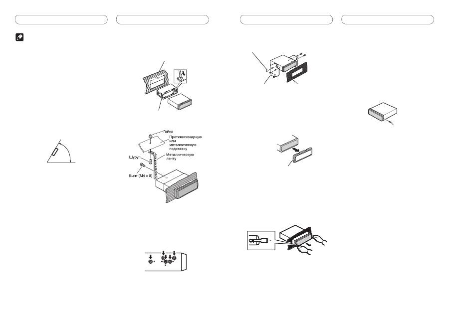
• Оптимальное изображение не получается, когда
устройство установлено под углом меньше чем
60°.
60°
Переднее/Заднее крепление
по стандарту DIN
Крепление данного устройства можно
выполнять как “спереди” (стандартное
переднее крепление DIN), так и “сзади”
(заднее крепление DIN с использованием
резьбовых отверстий для винтов,
расположенных по бокам рамы устройства).
Более подробная информация приведена
ниже в иллюстрированном описании методов
установки.
• При установке используйте детали,
имеющиеся в продаже.
Переднее крепление стандарта
DIN
1. Вставьте монтажную обойму в
переднюю панель.
При установке в недостаточно глубоком
гнезде используйте монтажную обойму,
входящую в комплект поставки устройства.
При наличии достаточного пространства
за устройством применяется монтажная
обойма, поставляемая вместе с автомобилем.
2. Закрепите монтажную обойму,
подогнув с помощью отвертки
металлические язычки (90°) на
место.
Приборная панель
Монтажная обойма
3. Установите устройство, как
показано на рисунке.
• Убедитесь, что устройство надежно
закреплено на месте. Неустойчивая установка
устройства может привести к его выпадению
или другим неполадкам в работе.
Заднее крепление стандарта DIN
1. Совместите отверстия на
кронштейне и боковыхпанелях
устройства.
2. Затяните по два винта с каждой
стороны.
Приборная панель или
консольConsole
Монтажный кронштейн
Самонарезающий винт (5 мм × 8 мм)
Демонтаж устройства
1. Выдвиньте верхнюю и нижнюю
часть декоративной рамки наружу,
чтобы снять ее. (При установке
рамки ее сторона с канавкой
должна быть направлена вниз.)
Декоративная рамка
• Снятие передней панели облегчает доступ к
декоративной рамке.
2. Вставьте прилагаемые
экстракторы с обеихстор он
устройства до щелчка.
3. Вытяните устройство из
приборной панели автомобиля.
Снятие и установка передней
панели
В целях защиты от кражи переднюю панель
можно снять.
Нажмите на кнопку снятия панели и потяните
панель вверх и на себя.
Подробнее см. в Руководстве по
эксплуатации.
Закрепление передней панели
Если вы не планируете отсоединять
переднюю панель, то она может быть
закреплена с помощью поставляемого винта.
Винт
<QRD3072-A> <>
26. Power amp
(sold separately)
27. Connect with RCA cables
(sold separately)
28. System remote control
26. Power amp
(sold separately)
26. Power amp
(sold separately)
24. To front output
23. To rear output
31. Rear speaker
29. Subwoofer
30. Front speaker
31. Rear speaker
29. Subwoofer
30. Front speaker
25. To subwoofer output
32. Perform these connections when
using the optional amplifier.
2*
1*
3*
4*
9.
Note
Depending on the kind of vehicle,
the function of 2* and 4* may be
different. In this case, be sure to
connect 1* to 4* and 3* to 2*.
10. Connect leads of the
same color to each other.
11. Yellow (2*)
Back-up (or
accessory)
13. Red (4*)
Accessory
(or back-up)
12. Yellow (1*)
Connect to the constant
12 V supply terminal.
14. Red (3*)
Connect to terminal controlled by
ignition switch (12 V DC).
22. Speaker leads
White:
Front left
White/black: Front left
Gray:
Front right
Gray/black: Front right
Green:
Rear left
or subwoofer
Green/black: Rear left
or subwoofer
Violet:
Rear right
or subwoofer
Violet/black: Rear right
or subwoofer
19. Blue/white
Connect to system control
terminal of the power amp (max.
300 mA 12 V DC).
20. Blue/white (6*)
Connect to auto-antenna relay
control terminal (max. 300 mA
12 V DC).
16. Black (chassis ground)
Connect to a clean, paint-free metal location.
The pin position of the ISO
connector will differ depending
on the type of vehicle. Connect
5* and 6* when Pin 5 is an
antenna control type. In another
type of vehicle, never connect
5* and 6*.
21. Blue/white (5*)
17. ISO connector
Note
In some vehicles, the ISO connector may be
divided into two. In this case, be sure to
connect to both connectors.
18. Yellow/black
If you use an equipment with Mute
function, wire this lead to the Audio Mute
lead on that equipment. If not, keep the
Audio Mute lead free of any connections.
8.
Notes
• Change the initial setting of this unit (refer to the
operation manual). The subwoofer output of this unit is
monaural.
• When using a subwoofer of 70 W (2
Ω
), be sure to
connect with Violet and Violet/black leads of this unit.
Do not connect anything with Green and Green/black
leads.
15. Orange/white
Connect to lighting switch terminal.
1. This product
7. Antenna
jack
6. Fuse (10 A)
5. Wired remote input
Hard-wired remote
control adaptor can
be connected (sold
separately).
2. Rear output
4. Subwoofer output
3. Front output
<QRD3072-A> <0>
Connecting the units English Connecting the units English
Note
• When this unit is installed in a vehicle without
ACC (accessory) position on the ignition switch,
red cable must be wired to the terminal that can
detect the operation of the ignition key. Otherwise,
battery drain may result.
ACC ON
S
TA
RT
O
FF
ON
S
TA
RT
O
FF
ACC position
No ACC position
• Use this unit in other than the following
conditions could result in fire or malfunction.
— Vehicles with a 12-volt battery and negative
grounding.
— Speakers with 50 W (output value) and 4 ohm
to 8 ohm (impedance value).
• To prevent short-circuit, overheating or
malfunction, be sure to follow the directions
below.
— Disconnect the negative terminal of the
battery before installation.
— Secure the wiring with cable clamps or
adhesive tape. To protect the wiring, wrap
adhesive tape around them where they lie
against metal parts.
— Place all cables away from moving parts, such
as gear shift and seat rails.
— Place all cables away from hot places, such as
near the heater outlet.
— Do not pass the yellow cable through a hole
into the engine compartment to connect to a
battery.
— Cover any disconnected cable connectors with
insulating tape.
— Do not shorten any cables.
— Never cut the insulation of the power cable of
this unit in order to share the power to other
equipment. Current capacity of the cable is
limited.
— Use a fuse of the rating prescribed.
— Never wire the speaker negative cable directly
to ground.
— Never band together multiple speaker’s
negative cables.
• Control signal is output through blue/white cable
when this unit is powered on. Connect it to an
external power amp’s system remote control or
the vehicle’s auto-antenna relay control terminal
(max. 300 mA, 12 V DC). If the vehicle is equipped
with a glass antenna, connect it to the antenna
booster power supply terminal.
• Never connect blue/white cable to external power
amp’s power terminal. Also, never connect
it to the power terminal of the auto antenna.
Otherwise, battery drain or malfunction may
result.
• Black cable is ground. This cable and other
product’s ground cable (especially, high-current
products such as power amp) must be wired
separately. Otherwise, fire or malfunction may
result if they are accidentally detached.
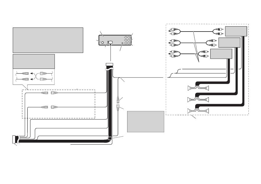
Connection Diagram
1. This product
2. Rear output
3. Front output
4. Subwoofer output
5. Wired remote input
Hard-wired remote control adaptor can be
connected (sold separately).
6. Fuse (10 A)
7. Antenna jack
8. Notes
• Change the initial setting of this unit (refer
to the operation manual). The subwoofer
output of this unit is monaural.
• When using a subwoofer of 70 W (2
Ω
), be
sure to connect with Violet and Violet/black
leads of this unit. Do not connect anything
with Green and Green/black leads.
9. Note
Depending on the kind of vehicle, the function
of 2* and 4* may be different. In this case, be
sure to connect 1* to 4* and 3* to 2*.
10. Connect leads of the same color to each other.
11. Yellow (2*)
Back-up (or accessory)
12. Yellow (1*)
Connect to the constant 12 V supply terminal.
13. Red (4*)
Accessory (or back-up)
14. Red (3*)
Connect to terminal controlled by ignition
switch (12 V DC).
15 Orange/white
Connect to lighting switch terminal.
16. Black (chassis ground)
Connect to a clean, paint-free metal location.
17. ISO connector
Note
In some vehicles, the ISO connector may
be divided into two. In this case, be sure to
connect to both connectors.
18. Yellow/black
If you use an equipment with Mute function,
wire this lead to the Audio Mute lead on that
equipment. If not, keep the Audio Mute lead
free of any connections.
19. Blue/white
Connect to system control terminal of the
power amp (max. 300 mA 12 V DC).
20. Blue/white (6*)
Connect to auto-antenna relay control terminal
(max. 300 mA 12 V DC).
21. Blue/white (5*)
The pin position of the ISO connector will differ
depending on the type of vehicle. Connect 5*
and 6* when Pin 5 is an antenna control type.
In another type of vehicle, never connect 5*
and 6*.
22. Speaker leads
White: Front left
+
White/black: Front left
*
Gray: Front right
+
Gray/black: Front right
*
Green: Rear left
+
or subwoofer
+
Green/black: Rear left
*
or subwoofer
*
Violet: Rear right
+
or subwoofer
+
Violet/black: Rear right
*
or subwoofer
*
23. To rear output
24. To front output
25. To subwoofer output
26. Power amp (sold separately)
27. Connect with RCA cables (sold separately)
28. System remote control
29. Subwoofer
30. Front speaker
31. Rear speaker
32. Perform these connections when using the
optional amplifier.

<QRD3072-A> <>
Connexions des appareils Français Connexions des appareils Français
Remarque
• Si cet appareil est installé dans un véhicule sans
position ACC (accessoire) sur le commutateur
d’allumage, le câble rouge doit être connecté
à une borne qui peut détecter la position du
commutateur d’allumage. Sinon, la batterie risque
de se décharger.
ACC ON
S
TA
RT
O
FF
ON
S
TA
RT
O
FF
Position ACC
Pas de position ACC
• Utiliser cet appareil dans d’autres conditions
que les conditions suivantes peut entraîner un
incendie ou un mauvais fonctionnement.
— Véhicule avec une batterie de 12 volts et une
mise à la masse négative.
— Enceintes de 50 W (valeur de sortie) et de 4
ohms à 8 ohms (valeur d’impédance).
• Pour éviter tout court-circuit, surchauffe ou
mauvais fonctionnement, assurez-vous de suivre
les instructions ci-dessous.
— Déconnectez la borne négative de la batterie
avant l’installation.
— Fixez solidement les câbles avec des serre-
câbles ou du ruban adhésif. Pour protéger
le câblage, entourez-le de ruban adhésif à
l’endroit où il est en contact avec des pièces
métalliques.
— Tenez tous les câbles à l’écart des parties
mobiles, telles que le levier de vitesse et les
rails des sièges.
— Tenez tous les câbles à l’écart des endroits
chauds, tels que les sorties du chauffage.
— Ne faites pas passer le câble jaune par un
trou dans le compartiment du moteur pour le
connecter à la batterie.
— Recouvrez tous les câbles non connectés avec
du ruban isolant.
— Ne raccourcissez aucun câble.
— Ne coupez jamais l’isolant du câble
d’alimentation de cet appareil afin de partager
l’alimentation avec un autre appareil. La
capacité électrique du câble est limitée.
— Utilisez un fusible de la valeur donnée.
— Ne connectez jamais le câble négatif des
enceintes directement à la masse.
— N’attachez jamais ensemble plusieurs câbles
négatifs de plusieurs enceintes.
• Le signal de commande est sorti par le câble
bleu/blanc quand cet appareil est sous
tension. Connectez-le à la télécommande
d’un système d’amplification extérieur ou à la
prise de commande du contrôle de relais de
l’antenne automatique (max. 300 mA, 12 V CC).
Si le véhicule est équipée d’une antenne de
vitre, connectez-la à la prise d’alimentation de
l’amplificateur d’antenne.
• Ne connectez jamais le câble bleu/blanc à la prise
d’alimentation d’un amplificateur extérieur. Et ne
le connectez jamais à la prise d’alimentation de
l’antenne automatique. Sinon, la batterie risque
de se décharger ou un mauvais fonctionnement
peut se produire.
• Le câble noir est pour la masse. Ce câble et
les câbles de masse des autres produits (en
particulier les appareils à haute intensité tels
que les amplificateurs) doivent être câblés
séparément. Sinon, ils peuvent entraîner un
incendie ou un mauvais fonctionnement s’ils se
détachent.
Diagramme de connexion
1. Cet appareil
2. Sortie arrière
3. Sortie avant
4. Sortie de caisson de grave
5. Entrée de télécommande câblée
Un adaptateur de télécommande câblée peut
être connecté (vendu séparément).
6. Fusible (10 A)
7. Prise d’antenne
8. Remarques
• Change le réglage initial de cet appareil
(reportez-vous au mode d’emploi). La sortie
de caisson de grave de cet appareil est
monophonique.
• Lors de l’utilisation d’un caisson de grave de
70 W (2
Ω
), assurez-vous de le raccorder aux
câbles Violet et Violet/noir de cet appareil. Ne
connectez rien aux câbles Vert et Vert/noir.
9. Remarque
En fonction du type de véhicule, la fonction de
2* et de 4* peut différer. Dans ce cas, assurez-
vous de connecter 1* à 4* et 3* à 2*.
10. Connectez les câbles de la même couleur les
uns aux autres.
11. Jaune (2*)
Secours (ou accessoire)
12. Jaune (1*)
Connectez à une prise d’alimentation
constante 12 V.
13. Rouge (4*)
Accessoire (ou secours)
14. Rouge (3*)
Connectez à une prise commandée par le
commutateur d’allumage (12 V CC).
15. Orange/blanc
Connectez à la prise du commutateur
d’éclairage.
16. Noire (masse au châssis)
Connectez à une section métallique propre et
sans peinture.
17. Connecteur ISO
Remarque
Dans certains véhicule, le connecteur ISO peut
être divisé en deux. Dans ce cas, assurez-vous
de faire la connexion aux deux connecteurs.
18. Jaune/noir
Si vous utilisez un appareil muni d’une
fonction de mise en sourdine, connectez ce
conducteur au conducteur de sourdine audio
de cet appareil. Sinon, laisser le fil de mise en
sourdine audio sans aucune connexion.
19. Bleu/blanc
Connectez à la prise de commande du système
de l’amplificateur de puissance (max. 300 mA
12 V CC).
20. Bleu/blanc (6*)
Connectez à la prise du contrôle de relais de
l’antenne automatique (max. 300 mA, 12 V CC).
21. Bleu/blanc (5*)
La position des broches du connecteur ISO
diffère en fonction du type de véhicule.
Connectez 5* et 6* quand la broche 5
correspond à la commande de l’antenne. Dans
les autres cas, ne connectez jamais 5* et 6*.
22. Câbles d’enceinte
Blanc: Avant gauche
+
Blanc/noir: Avant gauche
*
Gris: Avant droit
+
Gris/noir: Avant droit
*
Vert: Arrière gauche
+
ou caisson de grave
+
Vert/noir: Arrière gauche
*
ou caisson de grave
*
Violet: Arrière droit
+
ou caisson de grave
+
Violet/noir: Arrière droit
*
ou caisson de grave
*
23. À la sortie arrière
24. À la sortie avant
25. À la sortie du caisson de grave
26. Amplificateur de puissance (vendu séparément)
27. Connectez aux câbles cinch (RCA) (vendus
séparément)
28. Télécommande du système
29. Caisson de grave
30. Enceinte avant
31. Enceinte arrière
32. Réalisez ces connexions lors de l’utilisation de
l’amplificateur en option.

<QRD3072-A> <2>
Collegamento delle unità Italiano Collegamento delle unità Italiano
Nota
• Qualora l’unità venga installata in un veicolo la
cui chiavetta di accensione è sprovvista della
posizione ACC (accessori), il cavo rosso deve
essere collegato al terminale in grado di rilevare la
rotazione della chiavetta stessa.
In caso contrario la batteria si scaricherebbe.
ACC ON
S
TA
RT
O
FF
ON
S
TA
RT
O
FF
Posizione ACC
Assenza di posizione ACC
• L’impiego dell’unità in condizioni diverse
dalle seguenti potrebbe dar luogo a incendi o
malfunzionamenti:
— Veicoli provvisti di batteria da 12 V con messa
a terra sul negativo.
— Altoparlanti da 50 W (uscita) e da 4 ohm a
8 ohm (impedenza).
• Per impedire il verificarsi di cortocircuiti, di
surriscaldamento o di malfunzionamenti
raccomandiamo di osservare le seguenti
istruzioni.
— Prima di procedere con l’installazione
scollegate il terminale negativo della batteria.
— Bloccate i cavi con apposite fascette o con
del nastro adesivo. Per proteggere i cavi che
scorrono contro le parti metalliche del veicolo
avvolgeteli inoltre con del nastro adesivo.
— Allontanate tutti i cavi da qualsiasi parte in
movimento quali, ad esempio, la leva del
cambio e le guide dei sedili.
— Allontanate tutti i cavi da punti ad elevata
temperatura quali, ad esempio, gli effusori del
sistema di riscaldamento del veicolo.
— Per collegare il cavo giallo alla batteria non
fatelo passare per un foro ricavato nella
struttura di separazione dal vano del motore.
— Proteggete con del nastro adesivo tutti i
connettori non usati.
— Non accorciate alcun cavo di collegamento.
— Non tagliate la guaina d’isolamento del cavo
di alimentazione di questa unità in modo
da prelevare corrente per alimentare altri
apparecchi. La capacità di corrente di questo
cavo è infatti limitata.
— Usate solo un fusibile della capacità prescritta.
— Non collegate mai direttamente a terra il cavo
negativo degli altoparlanti.
— Non raggruppate fra loro il cavo negativo di
più altoparlanti.
• Quando l’unità è accesa il segnale di controllo
è posto in uscita attraverso il cavo blu/bianco.
Collegatelo al telecomando di un amplificatore
di potenza esterno o al terminale di controllo del
relé dell’antenna automatica del veicolo (massimo
300 mA e 12 V CC). Se il veicolo è provvisto di
un’antenna da vetro collegatela al terminale di
alimentazione del relativo booster.
• Non collegate il cavo blu/bianco al terminale
di alimentazione dell’amplificatore di potenza
esterno. Non collegatelo inoltre al terminale di
alimentazione dell’antenna.
In caso contrario la batteria si scaricherebbe
oppure si potrebbero verificare dei
malfunzionamenti.
• Il cavo nero va usato solo per la messa a terra.
Questo cavo e il cavo di messa a terra di altri
apparecchi (in particolare quelli ad alta corrente
quali gli amplificatori di potenza) devono essere
collegati separatamente.
In caso contrario, qualora si scolleghino
accidentalmente, si potrebbero verificare incendi
o malfunzionamenti.
Schema di collegamento
1. Questo apparecchio
2. Uscita posteriore
3. Uscita anteriore
4. Uscita del subwoofer
5. Ingresso del telecomando a filo
Qui si collega l’adattatore del telecomando a
filo (venduto a parte).
6. Fusibile (10 A)
7. Presa d’antenna
8. Note
• Cambiare l’impostazione iniziale di questa
unità (far riferimento al manuale d’istruzioni).
L’uscita subwoofer di questa unità è di tipo
mono.
• Se s’impiega un subwoofer da 70 W (2
Ω
) è
necessario collegarlo con i cavi viola e viola/
nero di questa unità. Nulla deve invece essere
collegato con i cavi verde e verde/nero.
9. Nota
A seconda del tipo di veicolo le funzione di 2*
e di 4* potrebbe differire. In tal caso collegare
1* a 4* e 3* a 2*.
10. Collegare fra loro i cavi di uguale colore.
11. Giallo (2*)
Retromarcia (o per accessori)
12. Giallo (1*)
Da collegare al terminale costantemente
alimentato a 12 V.
13. Rosso (4*)
Accessori (o retromarcia)
14. Rosso (3*)
Da collegare al terminale controllato dalla
chiavetta di accensione (12 V CC).
15. Arancione/bianco
Collegare al terminale dell’interruttore
d’illuminazione.
16. Nero (messa a terra sulla carrozzeria)
Da collegare in un punto metallico pulito e non
verniciato.
17. Connettore ISO
Nota
In alcuni veicoli il connettore ISO potrebbe
essere separato in due. In tal caso è necessario
collegare entrambi.
18. Giallo/nero
Questo cavo deve essere collegato al cavo di
silenziamento audio dell’eventuale apparecchio
provvisto della funzione di silenziamento,
qualora sia effettivamente utilizzato. In caso
contrario non lo si deve collegare.
19. Blu/bianco
Da collegare al terminale di controllo di sistema
dell’amplificatore di potenza (massimo 300 mA
12 V CC).
20. Blu/bianco (6*)
Da collegare al terminale di controllo del relé
dell’antenna automatica (massimo 300 mA
12 V CC).
21. Blu/bianco (5*)
La posizione dei contatti del connettore ISO
può differire in funzione del tipo di veicolo.
Collegare 5* e 6* qualora il contatto 5 sia del
tipo per controllo dell’antenna. In altri tipi di
veicolo 5* e 6* non devo mai essere collegati.
22. Cavi altoparlanti
Bianco: anteriore sinistro
+
Bianco/nero: anteriore sinistro
*
Grigio: anteriore destro
+
Grigio/nero: anteriore destro
*
Verde: posteriore sinistro
+
o subwoofer
+
Verde/nero: posteriore sinistro
*
o subwoofer
*
Viola: posteriore destro
+
o subwoofer
+
Viola/nero: posteriore destro
*
o subwoofer
*
23. All’uscita posteriore
24. All’uscita anteriore
25. All’uscita del subwoofer
26. Amplificatore di potenza (venduto a parte)
27. Da collegare con i cavi RCA (venduti a parte)
28. Telecomando del sistema
29. Subwoofer
30. Diffusore anteriore
31. Diffusore posteriore
32. Questi collegamenti devono essere eseguiti
quando s’impiega l’amplificatore opzionale.
<QRD3072-A> <3>
Conexión de las unidades Español Conexión de las unidades Español
Nota
• Cuando se instale esta unidad en un vehículo
sin la posición ACC (accesorio) en el interruptor
de encendido, se debe conectar el cable rojo al
terminal que puede detectar la operación de la
llave de encendido.
De lo contrario, la batería puede descargarse.
ACC ON
S
TA
RT
O
FF
ON
S
TA
RT
O
FF
Posición ACC
Sin posición ACC
• El uso de esta unidad en condiciones diferentes
de las siguientes podría causar un fuego o fallo de
funcionamiento.
— Vehículos con una batería de 12 voltios y
puesta a tierra negativa.
— Altavoz con 50 W (valor de salida) y de 4
ohmios a 8 ohmios (valor de impedancia).
• Para prevenir cortocircuitos, sobrecalentamiento
o fallo de funcionamiento, asegúrese de seguir las
instrucciones a continuación.
— Desenchufe el terminal negativo de la batería
antes de la instalación.
— Fije el cableado con abrazaderas de cable o
con cinta adhesiva. Para proteger el cableado,
envuélvalo con cinta adhesiva donde el
cableado se apoya sobre piezas metálicas.
— Posicione todos los cables alejados de las
piezas móviles, como el cambio de marchas y
rieles de los asientos.
— Posicione todos los cables alejados de
lugares calientes como cerca de la salida del
calentador.
— No pase el cable amarillo a través de un
agujero en el compartimiento del motor para
conectar la batería.
— Cubra cualquier conector de cable
desconectado con cinta de aislamiento.
— No acorte ningún cable.
— No corte nunca el aislamiento del cable de
alimentación de esta unidad para compartir
la energía con otro equipo. La capacidad de
corriente del cable es limitada.
— Utilice un fusible con la capacidad
especificada.
— No conecte nunca el cable negativo de altavoz
directamente a la puesta a tierra.
— No junte nunca múltiples cables negativos de
altavoz.
• La señal de control se emite a través del cable
azul/blanco cuando se enciende esta unidad.
Conéctelo a un terminal de control de sistema de
amplificador de potencia externo o al terminal de
control de relé de antena automática del vehículo
(máx. 300 mA, 12 V CC). Si el vehículo está
equipado con una antena de vidrio, conéctelo al
terminal de suministro de potencia de refuerzo de
la antena.
• No conecte nunca el cable azul/blanco al
terminal de alimentación de un amplificador
de potencia externo. Igualmente, no conéctelo
nunca al terminal de alimentación de la antena
automática.
De lo contrario, puede ocurrir la descarga de la
batería o un fallo de funcionamiento.
• El cable negro es para la puesta a tierra. Se debe
conectar este cable y el cable de puesta a tierra
de otro producto (especialmente de productos de
alta corriente como un amplificador de potencia)
separadamente. De lo contrario, puede ocurrir un
fuego o fallo de funcionamiento si los cables se
sueltan accidentalmente.
Diagrama de conexión
1. Este producto
2. Salida trasera
3. Salida delantera
4. Salida de altavoz de subgraves
5. Entrada remota cableada
Se puede conectar el adaptador de control
remoto cableado (vendido separadamente).
6. Fusible (10 A)
7. Toma de antena
8. Notas
• Cambie el ajuste inicial de esta unidad
(refiérase al manual de operación). La salida
de altavoz de subgraves de esta unidad es
monofónica.
• Cuando utilice un altavoz de subgraves de
70 W (2
Ω
), asegúrese de conectarlo con
los hilos Violeta y Violeta/negro de esta
unidad. No conecte nada con los hilos Verde
y Verde/negro.
9. Nota
Dependiendo del tipo de vehículo, la función
de 2* y 4* puede ser diferente. En este caso,
asegúrese de conectar 1* a 4* y 3* a 2*.
10. Conecte los hilos del mismo color a cada otro.
11. Amarillo (2*)
Reserva (o accesorio)
12. Amarillo (1*)
Conecte el terminal de suministro de 12 V
constante.
13. Rojo (4*)
Accesorio (o reserva)
14. Rojo (3*)
Conecte al terminal controlado por del
interruptor de encendido (12 V CC).
15. Anaranjado/blanco
Conecte al terminal de interruptor de
iluminación.
16. Negro (masa de la carrocería)
Conecte a un punto de metal limpio, libre de
pintura.
17. Conector ISO
Nota
En algunos vehículos, puede que el conector
ISO esté dividido en dos. En este caso,
asegúrese de conectar a ambos conectores.
178.
Amarillo/negro
Si se utiliza un equipo con función de
silenciamiento, conecte este conductor con el
conductor de silenciamiento de audio en tal
equipo. Si no, mantenga el silenciamiento de
audio libre de cualquier conexión.
19. Azul/blanco
Conecte al terminal de control de sistema del
amplificador de potencia (máx. 300 mA 12 V
CC).
20. Azul/blanco (6*)
Conecte al terminal de control de relé de
antena automática (máx. 300 mA 12 V CC).
21. Azul/blanco (5*)
La posición de los contactos del conector ISO
difiere dependiendo del tipo del vehículo.
Conecte 5* y 6* cuando el contacto 5 es del
tipo de control de antena. En otros tipos de
vehículo, no conecte nunca 5* y 6*.
22. Hilos de altavoz
Blanco: Izquierda delantera
+
Blanco/negro: Izquierda delantera
*
Gris: Derecha delantera
+
Gris/negro: Derecha delantera
*
Verde: Izquierda trasera
+
o altavoz de subgraves
+
Verde/negro: Izquierda trasera
*
o altavoz de subgraves
*
Violeta: Derecha trasera
+
o altavoz de subgraves
+
Violeta/negro: Derecha trasera
*
o altavoz de subgraves
*
23. A la salida trasera
24. A la salida delantera
25. A la salida del altavoz de subgraves
26. Amplificador de potencia (vendido
separadamente)
27. Conecte los cables RCA (vendidos
separadamente)
28. Control remoto de sistema
29. Altavoz de subgraves
30. Altavoz delantero
31. Altavoz trasero
32. Realice estas conexiones cuando utilice el
amplificador opcional.

<QRD3072-A> <>
Anschließen der Geräte Deutsch Anschließen der Geräte Deutsch
Hinweise
• Wenn dieses Gerät in einem Auto eingebaut wird,
das auf dem Zündschalter keine ACC (Zubehör)-
Position hat, sollte die rote Leitung des Geräts
an eine Klemme angeschlossen werden, die die
Position des Zündschalters erfassen kann.
Anderenfalls kann die Autobatterie entleert
werden.
ACC ON
S
TA
RT
O
FF
ON
S
TA
RT
O
FF
ACC-Position
Keine ACC-Position
• Wenn das Gerät nicht unter den folgenden
Bedingungen eingebaut wird, kann ein Brand
oder eine Funktionsstörung auftreten.
— Fahrzeuge mit einer 12-Volt-Batterie und
negativer Erdung.
— Lautsprecher mit 50 W (Ausgangsleistung)
und 4 Ohm bis 8 Ohm (Impedanz).
• Um Kurzschlüsse, eine Überhitzung oder
Funktionsstörung zu verhindern, befolgen Sie bitte
die folgenden Hinweise:
— Trennen Sie die negative Klemme der Batterie
vor dem Einbau ab.
— Sichern Sie die Leitungen mit Kabelklemmen
oder Klebeband. Zum Schutz der Leitungen
sollten sie an Stellen, wo sie Metallteile
berühren, mit Klebeband umwickelt werden.
— Verlegen Sie alle Leitungen so, dass keine
beweglichen Teile, wie die Gangschaltung und
die Sitzschienen, berühren.
— Verlegen Sie alle Kabel so, dass sie von heißen
Stellen, wie etwa der Heizungsauslassöffnung
entfernt sind.
— Führen Sie die gelbe Leitung zum Anschluss
an die Batterie nicht durch ein Loch in den
Motorraum ein.
— Umwickeln Sie abgetrennte Leitungen mit
Isolierband.
— Verkürzen Sie keine Kabel.
— Führen Sie niemals anderen Geräten
Strom zu, indem Sie die Isolierung der
Stromversorgungsleitung dieses Geräts
durchschneiden und davon Strom abzapfen.
Die Strombelastbarkeit der Leitung ist
begrenzt.
— Verwenden Sie eine Sicherung mit dem
vorgeschriebenen Nennwert.
— Schließen Sie das negative Lautsprecherkabel
nie direkt an die Erdung an.
— Bündeln Sie nie die negativen Kabeln
mehrerer Lautsprecher.
• Das Steuersignal wird über das blaue/
weiße Kabel ausgegeben, wenn dieses
Gerät eingeschaltet wird. Schließen Sie
es an eine System-Fernbedienung eines
externen Leistungsverstärkers oder an die
Autoantennenrelais-Steuerungsklemme
des Fahrzeugs an (max. 300 mA, 12 V
Gleichspannung). Wenn das Fahrzeug
mit einer Fensterantenne ausgestattet ist,
schließen Sie es an die Antennenverstärker-
Stromversorgungsklemme an.
• Schließen Sie das blaue/weiße Kabel nie an
die Leistungsklemme des Verstärkers an.
Außerdem darf das blaue/weiße Kabel nicht
an die Leistungsklemme der Auto-Antenne
angeschlossen werden. Ein solcher Anschluss
könnte zu einer Belastung der Batterie führen und
Funktionsstörungen verursachen.
• Das schwarze Kabel ist das Erdungskabel. Dieses
Kabel ist getrennt von der Erde von Hochstrom-
Geräten, wie z. B. Leistungsverstärkern, zu
erden. Anderenfalls besteht die Gefahr einer
Beschädigung der Geräte oder eines Brandes,
falls die Erdungsstelle versehentlich abgetrennt
wird.
Anschlussdiagramm
1. Dieses Produkt
2. Hinterer Ausgang
3. Vorderer Ausgang
4. Subwoofer-Ausgang
5. Buchse für die verdrahtete Fernbedienung
Hier kann ein Drahtfernbedienungsadapter
(getrennt erhältlich) angeschlossen werden.
6. Sicherung (10 A)
7. Antennebuchse
8. Hinweise
• Ändern Sie die Grundeinstellung dieses
Geräts (siehe Bedienungsanleitung). Der
Subwoofer-Ausgang dieses Geräts ist Mono.
• Bei Verwendung eines Subwoofers von 70 W
(2
Ω
) achten Sie darauf, den Anschluss an die
violetten und violetten/schwarzen Leitungen
dieses Geräts herzustellen. Stellen Sie keinen
Anschluss mit den grünen und grünen/
schwarzen Leitungen her.
9. Hinweis:
Je nach Art des Fahrzeugs besitzen 2* und 4*
u. U. unterschiedliche Funktionen. Verbinden
Sie in einem solchen Fall 1* mit 4* und 3* mit
2*.
10. Verbinden Sie Leitungen derselben Farbe
miteinander.
11. Gelb (2*)
Reserve (oder Zubehör)
12. Gelb (1*)
An eine Stromversorgung anschließen, die
immer Gleichstrom von 12 V führt.
13. Rot (4*)
Zubehör (oder Reserve)
14. Rot (3*)
An eine Stromversorgung anschließen, (12 V
Gleichspannung), die mit dem Zündschloss ein-/
ausgeschaltet wird.
15. Orangefarben/weiß
An die Lichtschalterklemme anschließen.
16. Schwarz (Erdung)
An ein sauberes Metallteil anschließen, das von
Farbe frei ist.
17. ISO-Anschluss
Hinweis:
Bei einigen Fahrzeugen kann der ISO-
Steckverbinder in zwei Hälften geteilt sein. In
diesem Fall ist der Anschluss unbedingt an
beiden Steckverbindern vorzunehmen.
18. Gelb/schwarz
Falls Sie ein Gerät mit Stummschaltfunktion
(Mute) verwenden, verdrahten Sie dieses
Kabel mit der Audio Mute-Leitung am
entsprechenden Gerät. Andernfalls die Audio
Mute-Leitung frei von Anschlüssen lassen.
19. Blau/weiß
An den Systemsteuerungs-Anschluss des
Leistungsverstärkers (max. 300 mA, 12 V
Gleichspannung) anschließen.
20. Blau/weiß (6*)
An die Autoantennenrelais-Steuerungsklemme
anschließen (max. 300 mA, 12 V
Gleichspannung).
21. Blau/weiß (5*)
Die Pin-Position des ISO-Anschlusses
hängt vom Fahrzeugtyp ab. 5* und 6*
anschließen, wenn es sich bei Pin 5 um einen
Antennensteuerungstyp handelt. Bei einem
anderen Fahrzeugtyp 5* und 6* niemals
anschließen.
22. Lautsprecherzuleitungen
Weiß: Vorne links
+
Weiß/Schwarz: Vorne links
*
Grau: Vorne rechts
+
Grau/Schwarz: Vorne rechts
*
Grün: Hinten links
+
oder Subwoofer
+
Grün/Schwarz: Hinten links
*
oder Subwoofer
*
Violett: Hinten rechts
+
oder Subwoofer
+
Violett/Schwarz: Hinten rechts
*
oder Subwoofer
*
23. Zum hinteren Ausgang
24. Zum vorderen Ausgang
25. Zum Subwoofer-Ausgang
26. Leistungsverstärker (getrennt erhältlich)
27. Mit RCA-Kabeln verbinden (getrennt erhältlich)
28. System-Fernbedienung
29. Subwoofer
30. Vorderer Lautsprecher
31. Hinterer Lautsprecher
32. Bei Gebrauch des optionalen Verstärkers diese
Anschlüsse vornehmen.

<QRD3072-A> <>
Aansluiten van de toestellen Nederlands Aansluiten van de toestellen Nederlands
Opmerking
• Wanneer dit toestel geïnstalleerd is in een
voertuig zonder ACC (accessoire) stand op
het contactslot, moet de rode draad worden
verbonden met een aansluiting die de stand van
de contactsleutel kan herkennen. Anders kan de
accu leeglopen.
ACC ON
S
TA
RT
O
FF
ON
S
TA
RT
O
FF
ACC stand
Geen ACC stand
• Gebruik van dit toestel onder andere dan de
volgende omstandigheden kan leiden tot brand of
storingen.
— Voertuigen met een negatief geaarde 12 V
accu.
— Luidsprekers van 50 W (uitgangsvermogen) en
4 Ohm tot 8 Ohm (impedantie).
• Om kortsluiting, oververhitting of andere
storingen te voorkomen moet u de onderstaande
instructies opvolgen.
— Koppel de negatieve pool van de accu los voor
u begint met de installatie.
— Zet alle bedrading vast met kabelklemmen of
isolatieband. Ter bescherming van de
bedrading dient u deze te omwikkelen met
isolatieband waar de bedrading met metalen
onderdelen in aanraking komt.
— Houd alle bedrading uit de buurt van
bewegende onderdelen, zoals de
versnellingspook en de stoelenrails.
— Houd de bedrading uit de buurt van zeer
warme plekken, zoals bij een
verwarmingsrooster.
— Leid de gele draad niet door een gat naar het
motorcompartiment om aan te sluiten op de
accu.
— Plak eventuele losse aansluitingen,
draadeinden of stekkers netjes af met
isolatieband.
— Maak de kabels niet korter.
— Tap in geen geval de stroomkabel voor dit
toestel af om andere apparatuur van stroom
te voorzien. Het vermogen van de draad is
beperkt.
— Gebruik een zekering met het voorgeschreven
vermogen.
— Sluit de negatieve luidsprekerdraden in geen
geval direct op aarde aan.
— Bundel de negatieve luidsprekerdraden in
geen geval samen.
• Via de blauw/witte draad wordt een stuursignaal
geproduceerd wanneer dit toestel is ingeschakeld.
Verbind deze met de systeemafstandsbediening
van een externe eindversterker, of met de
stuuraansluiting voor het relais van de antenne
van het voertuig (max. 300 mA, 12 V
gelijkstroom). Als het voertuig een ruitantenne
heeft, dient u deze draad te verbinden met de
stroomaansluiting van de
antennesignaalversterker (booster).
• Verbind de blauw/witte draad in geen geval met
de stroomaansluiting van een externe
eindversterker. Verbind deze draad ook in geen
geval met de stroomaansluiting zelf van de
antenne van de auto. Doet u dit toch, dan kan de
accu leeglopen of kunnen zich andere storingen
voordoen.
• De zwarte draad is de aarding. Deze draad en de
aardingen van andere apparatuur (in het bijzonder
producten met een hoog vermogen, zoals een
eindversterker), moeten onafhankelijk van elkaar
worden aangesloten. Doet u dit niet, dan kan er
brand ontstaan of kunnen zich storingen
voordoen wanneer de bedrading onbedoeld los
raakt.
Aansluitingsschema
1. Dit product
2. Achter-uitgang
3. Voor-uitgang
4. Subwoofer uitgang
5. Afstandsbediening met draad
Er kan een adapter voor een afstandsbediening
met draad worden aangesloten (los
verkrijgbaar).
6. Zekering (10 A)
7. Antenne-aansluiting
8. Opmerkingen
• Verander de basisinstelling van dit toestel
(zie bladzijde de Gebruiksaanwijzing). De
subwoofer weergave van dit toestel is in
mono.
• Bij gebruik van een subwoofer van 70 W
(2
Ω
), moet u erop letten dat u de aansluiting
verricht met de paarse en paars/zwarte
draden van dit toestel. Sluit niets aan op de
groene en groen/zwarte draden.
9. Opmerking
Afhankelijk van het soort voertuig is het
mogelijk dat de functies van 2* en 4*
verschillen. Let er in een dergelijk geval op dat
u 1* op 4* en 3* op 2* aansluit.
10. Sluit in het algemeen draden van dezelfde
kleur op elkaar aan.
11. Geel (2*)
Back-up (of accessoire)
12. Geel (1*)
Verbinden met de continue 12 V
stroomaansluiting.
13. Rood (4*)
Accessoire (of back-up)
14. Rood (3*)
Verbinden met een elektrische aansluiting die
aangestuurd wordt via het contactslot
(12 V gelijkstroom).
15. Oranje/wit
Verbinden met de aansluiting van de
verlichtingsschakelaar.
16. Zwart (chassis aarde)
Aansluiten op een schone, blank metalen plek.
17. ISO stekker
Opmerking
In sommige voertuigen kan de ISO stekker
in twee stukken gedeeld zijn. Sluit in een
dergelijk geval beide stekkers aan.
18. Geel/zwart
Als u apparatuur met een zg. Mute functie
(geluid uit/dempen) gebruikt, dient u
deze draad te verbinden met de audio-
dempingsdraad van de betreffende apparatuur.
Maakt u daarvan geen gebruik, laat de Audio
Mute dempingsaansluiting dan vrij, zonder
hierop iets aan te sluiten.
19. Blauw/wit
Verbinden met de
systeembedieningsaansluiting van de
eindversterker (max. 300 mA 12 V
gelijkstroom).
20. Blauw/wit (6*)
Verbinden met de stuuraansluiting van het
relais van de antenne van het voertuig (max.
300 mA 12 V gelijkstroom).
21. Blauw/wit (5*)
De penposities van de ISO stekker hangen
mede af van het type voertuig. Sluit 5* en 6*
aan wanneer pen 5 de antenne aanstuurt.
In andere typen voertuigen hoeft u 5* en 6*
helemaal niet aan te sluiten.
22. Luidsprekerdraden
Wit: Links voor
+
Wit/zwart: Links voor
*
Grijs: Rechts voor
+
Grijs/zwart: Rechts voor
*
Groen: Links achter
+
of subwoofer
+
Groen/zwart: Links achter
*
of subwoofer
*
Paars: Rechts achter
+
of subwoofer
+
Paars/zwart: Rechts achter
*
of subwoofer
*
23. Naar de achter-uitgang
24. Naar de voor-uitgang
25. Naar de subwoofer uitgang
26. Eindversterker (los verkrijgbaar)
27. Aansluiten met RCA (tulpstekker) kabels (los
verkrijgbaar)
28. Systeemafstandsbediening
29. Subwoofer
30. Voor-luidspreker
31. Achter-luidspreker
32. Voer deze verbindingen uit wanneer u de los
verkrijgbare versterker gebruikt.

<QRD3072-A> <>
Подключение устройств Pycckий Подключение устройств Pycckий
Примечание
• Когда данное устройство устанавливается
в транспортном средстве без ACC
(вспомогательные приборы) положения на
замке зажигания, красный кабель должен
быть подключен к клемме, которая может
обнаруживать работу замка зажигания. Иначе, в
результате батарея может разрядиться.
ACC ON
S
TA
RT
O
FF
ON
S
TA
RT
O
FF
АСС положение
АСС положение нет
• Использование данного устройства в иных,
чем следующие условия, может привести к
возгоранию или неправильному срабатыванию.
— Автомобиль с батареей с 12-вольт и
отрицательным заземлением.
— Динамики с 50 Вт (выходная величина) и от 4
ОМ до 8 ОМ (полное сопротивление).
• Чтобы предотвратить короткое замыкание,
перегрев или неправильное срабатывание
убедитесь, что следуете указаниям ниже.
— Отсоедините отрицательную клемму батареи
пред установкой.
— Закрепите провода кабельными зажимами
или липкой лентой. Для защиты проводов
следует обмотать их липкой летной в
тех местах, где они соприкасаются с
металлическими частями.
— Прокладывайте все кабели вдали от
двигающихся частей, таких как рычаг
переключения коробки передач или
направляющая для выдвижения сиденья.
— Прокладывайте все кабели вдали от
горячих мест, таких как рядом с выпуском
нагревателя.
— Не пропускайте желтый кабель через
отверстие в моторном отсеке, для того чтобы
подключить его к батарее.
— Защитите все неподключенные кабели
разъемами с изоляционной лентой.
— Не укорачивайте какие-либо кабели.
— Никогда не обрезайте изоляцию питающего
кабеля данного устройства, чтобы подключить
питание на другое оборудование. Пропускная
способность кабеля ограничена.
— Используйте плавкий предохранитель
заданного номинала.
— Никогда не подключайте отрицательный
кабель динамика напрямую к заземлению.
— Никогда не связывайте вместе различные
отрицательные кабели динамиков.
• Контрольный сигнал выходит по сине/белому
кабелю, когда данное устройство подключено
к электропитанию. Подключите его к системе
дистанционного управления внешнего усилителя
мощности или к клемме реле управления
автомобильной антенны (макс. 300 мА, 12 В
пост. ток). Если автомобиль снабжен стеклянной
антенной, подключите её к питающему терминалу
антенного усилителя.
• Никогда не подключайте сине/белый кабель
к питающему терминалу внешнего усилителя
мощности. Так же, никогда не подключайте его к
питающему терминалу автомобильной антенны.
Иначе, в результате батарея разрядится или
будет происходить неправильное срабатывание.
• Черный кабель – заземление. Этот кабель и
кабели заземления других изделий (особенно,
сильноточные изделия, такие как усилитель
мощности) должны быть проложены раздельно.
Иначе, в результате может произойти возгорание
или неправильное срабатывание, если они
внезапно отсоединятся.
Схема Соединений
1. Данное устройство
2. Задний выход
3. Передний выход
4. Выход низкочастотого динамика
5. Дистанционный монтажный вход
Адаптер жестко смонтированного
дистанционного управления может быть
подключен (продается отдельно).
6. Плавкий предохранитель (10 A)
7. Гнездо антенны
8. Примечание
• Измените исходные настройки данного
устройства (См. Руководство по
эксплуатации). Низкочастотный динамик
данного устройства обеспечивает
монофонический выходной сигнал.
• Когда используется Низкочастотный
динамик 70 Вт (2 Ω), будьте уверены, что
соединили с Фиолетовым и Фиолетово/
Черным проводами данного устройства.
Ничего не соединяйте с Зеленым и Зелено/
Черным проводами.
9. Примечание
В зависимости от типа автомобиля функции
2* и 4* могут быть различными. В этом случае,
убедитесь, что 1* подключили к 4*, а 3* к 2*.
10. Соедините провода одинакового цвета друг с
другом.
11. Желтый (2*)
Разрывный (или вспомогательный)
12. Желтый (1*)
Подключите к клемме постоянно подающей
12 В.
13. Красный (4*)
Вспомогательный (или разрывный)
14. Красный (3*)
Подключите к клемме, контролируемой
замком зажигания (12 В пост. ток).
15. Оранжевый/белый
Подключить к клемме выключателя
освещения.
16. Черный (заземление на массу)
Подключите к чистому, неокрашенному
металлическому участку.
17. ISO разъем
Примечание
В некоторых автомобилях ISO разъем
может быть разделен на два. В этом случае
убедитесь, что подключили оба разъема.
18. Желтый/черный
Если вы пользуетесь устройством, на
котором предусмотрена функция отключения
звука, подключите данный провод к
проводу отключения звука на устройстве. В
противном случае, не подключайте провод
отключения звука к другим соединениям.
19. Синий/белый
Подключите к клемме системы контроля
усилителя мощности (макс. 300 мА 12 В пост.
ток).
20. Синий/белый (6*)
Подключите к клемме реле управления
автомобильной антенны (макс. 300 мА 12 В
пост. ток).
21. Синий/белый (5*)
Расположение штырей ISO разъема может
быть различным в зависимости от типа
автомобиля. Соедините 5* и 6* когда штырь
5 это штырь типа управления антенны.
В других типах автомобилей никогда не
соединяйте 5* и 6*.
22. Провода динамиков
Белый: Передний левый
+
Белый/черный: Передний левый
*
Серый: Передний правый
+
Серый/черный: Передний правый
*
Зеленый: Задний левый
+
или
низкочастотный динамик
+
Зеленый/черный: Задний левый
*
или
низкочастотный динамик
*
Фиолетовый: Задний правый
+
или
низкочастотный динамик
+
Фиолетовый/черный: Задний правый
*
или низкочастотный
динамик
*
23. К заднему выходу
24. К переднему выходу
25. К выходу низкочастотного динамика
26. Усилитель мощности (продается отдельно)
27. Соедините с кабелями RCA (продаются
отдельно)
28. Система дистанционного управления
29. Низкочастотный динамик
30. Передний динамик
31. Задний динамик
32. Выполните данные подключения, когда
используется усилитель, который не входит в
состав обязательного оборудования.


