Pioneer S-8EX-QL: instruction
Class: Household, kitchen appliances, electronics and equipment
Type: Home Theater System
Manual for Pioneer S-8EX-QL
Table of contents
- Contents
- Before you start What’s in the box
- About the EX series Technology behind the S-8EX
- Crossover Networks
- Installation and Placement How to install
- Using the Pioneer Speaker Stand CP-7EX Choosing Where To Place The Speaker Systems
- Connections Connecting to an amplifier Connecting the cables
- Single-Wire Connections Bi-Wire Connections
- Bi-Amplification Connections Vertical Bi-Amping Horizontal Bi-Amping
- Other Information Using the foam plugs Attaching/Removing the Grille Cover
- Specifications
1
En
http://www.pioneer.co.uk
(or http://www.pioneer.eu)
S-8EX_EN.book 1 ページ 2008年7月16日 水曜日 午後2時20分
2
En
Thank you for buying this Pioneer product.
Please read through these operating instructions so you will know how to operate your model properly.
After you have finished reading the instructions, put them away in a safe place for future reference.
Contents
Before you start
What’s in the box
About the EX series
Technology behind the S-8EX
. . . . . . . . . . . . . . . . . . . . . . . . . . . . . 4
CST
. . . . . . . . . . . . . . . . . . . . . . . . . . . . . . . . . . . . . . . . . . . . . . . . 4
Ceramic Graphite Diaphragm
. . . . . . . . . . . . . . . . . . . . . . . . . . . . 4
Magnesium Alloy Diaphragm
. . . . . . . . . . . . . . . . . . . . . . . . . . . . 4
Bass Drivers
. . . . . . . . . . . . . . . . . . . . . . . . . . . . . . . . . . . . . . . . . 4
Bass Enclosure Construction
. . . . . . . . . . . . . . . . . . . . . . . . . . . . 4
Crossover Networks
. . . . . . . . . . . . . . . . . . . . . . . . . . . . . . . . . . . 5
Collaboration with Air Studios
. . . . . . . . . . . . . . . . . . . . . . . . . . . 5
Installation and Placement
How to install
. . . . . . . . . . . . . . . . . . . . . . . . . . . . . . . . . . . . . . . . . 6
When installing directly on the floor
. . . . . . . . . . . . . . . . . . . . . . . 6
Using the furnished speaker base
. . . . . . . . . . . . . . . . . . . . . . . . 6
Using the Pioneer Speaker Stand CP-7EX
. . . . . . . . . . . . . . . . . . . 7
Choosing Where To Place The Speaker Systems
. . . . . . . . . . . . . 7
Connections
Connecting to an amplifier
. . . . . . . . . . . . . . . . . . . . . . . . . . . . . . . .8
Connecting the cables
. . . . . . . . . . . . . . . . . . . . . . . . . . . . . . . . . . .8
Single-Wire Connections
. . . . . . . . . . . . . . . . . . . . . . . . . . . . . . . .9
Bi-Wire Connections
. . . . . . . . . . . . . . . . . . . . . . . . . . . . . . . . . . .9
Bi-Amplification Connections
. . . . . . . . . . . . . . . . . . . . . . . . . . .10
Other Information
Using the foam plugs
. . . . . . . . . . . . . . . . . . . . . . . . . . . . . . . . . . .11
Using foam plugs A only
. . . . . . . . . . . . . . . . . . . . . . . . . . . . . . .11
Using both foam plugs A and B
. . . . . . . . . . . . . . . . . . . . . . . . . .11
Attaching/Removing the Grille Cover
. . . . . . . . . . . . . . . . . . . . . . .11
Cleaning the speaker cabinet
. . . . . . . . . . . . . . . . . . . . . . . . . . . . .11
Specifications
. . . . . . . . . . . . . . . . . . . . . . . . . . . . . . . . . . . . . . . .12
For U.S. model
S001_En
Selecting fine audio equipment such as the unit
you’ve just purchased is only the start of your
musical enjoyment. Now it’s time to consider how
you can maximize the fun and excitement your
equipment offers. This manufacturer and the
Electronic Industries Association’s Consumer
Electronics Group want you to get the most out of
your equipment by playing it at a safe level. One that
lets the sound come through loud and clear without
annoying blaring or distortion-and, most importantly,
without affecting your sensitive hearing.
Sound can be deceiving. Over time your hearing
“comfort level” adapts to higher volumes of sound.
So what sounds “normal” can actually be loud and
harmful to your hearing. Guard against this by
setting your equipment at a safe level BEFORE your
hearing adapts.
To establish a safe level:
• Start your volume control at a low setting.
• Slowly increase the sound until you can hear it
comfortably and clearly, and without distortion.
Once you have established a comfortable sound
level:
• Set the dial and leave it there.
Taking a minute to do this now will help to prevent
hearing damage or loss in the future. After all, we
want you listening for a lifetime.
We Want You Listening For A Lifetime
Used wisely, your new sound equipment will
provide a lifetime of fun and enjoyment. Since
hearing damage from loud noise is often
undetectable until it is too late, this manufacturer
and the Electronic Industries Association’s
Consumer Electronics Group recommend you avoid
prolonged exposure to excessive noise. This list of
sound levels is included for your protection.
Decibel
Level Example
30
Quiet library, soft whispers
40 Living room, refrigerator, bedroom away from traffic
50
Light traffic, normal conversation, quiet office
60
Air conditioner at 20 feet, sewing machine
70
Vacuum cleaner, hair dryer, noisy restaurant
80 Average city traffic, garbage disposals, alarm clock
at two feet.
THE FOLLOWING NOISES CAN BE DANGEROUS
UNDER CONSTANT EXPOSURE
90 Subway, motorcycle, truck traffic, lawn mower
100 Garbage truck, chain saw, pneumatic drill
120 Rock band concert in front of speakers,
thunderclap
140 Gunshot blast, jet plane
180 Rocket launching pad
Information courtesy of the Deafness Research Foundation.
S-8EX_EN.book 2 ページ 2008年7月16日 水曜日 午後2時20分
3
En
English
Before you start
• The nominal impedance of this speaker system is 6
Ω
.
Connect the speaker system to an amplifier with a load
impedance ranging from 6
Ω
to 16
Ω
(a model with “6
Ω
–
16
Ω
” displayed on the speaker output terminals).
In order to prevent damage to the speaker system resulting
from input overload, please observe the following precautions:
• Do not supply power to the speaker system in excess of the
maximum permissible input.
• When using a graphic equalizer to emphasize loud sounds in
the high-frequency range, do not use excessive amplifier
volume.
• Do not try to force a low-powered amplifier to produce loud
volumes of sound (the amplifier’s harmonic distortion will be
increased, and you may damage the speaker).
Caution: installation
• When placing this unit, ensure that it is firmly secured and
avoid areas where it may be likely to fall and cause injury in the
event of a natural disaster (such as an earthquake).
• Do not attach these speakers to the wall or ceiling. They may
fall off and cause injury.
• Do not install your speakers overhead on the ceiling or wall. If
improperly attached, the speaker grille can fall and cause
damage or personal injury.
• Switch off and unplug your AV equipment and consult the
instructions when connecting up components. Make sure you
use the correct connecting cables.
Caution: in use
• Do not place the speaker on an unstable surface. It could
present a hazard if it falls, as well as damaging the equipment.
• Do not use the speaker to output distorted sound for long
periods of times. This can result in a fire hazard.
• Do not sit or stand on the speaker, or let children play on the
speaker.
• Do not put large or heavy objects on top of the speaker.
• Do not place magnetic objects such as screwdrivers or iron
parts near the tweeter or midrange. Since the speakers use
strong magnets, the objects may be attracted, causing injury
or damaging the diaphragm.
For U.S. model
For European model
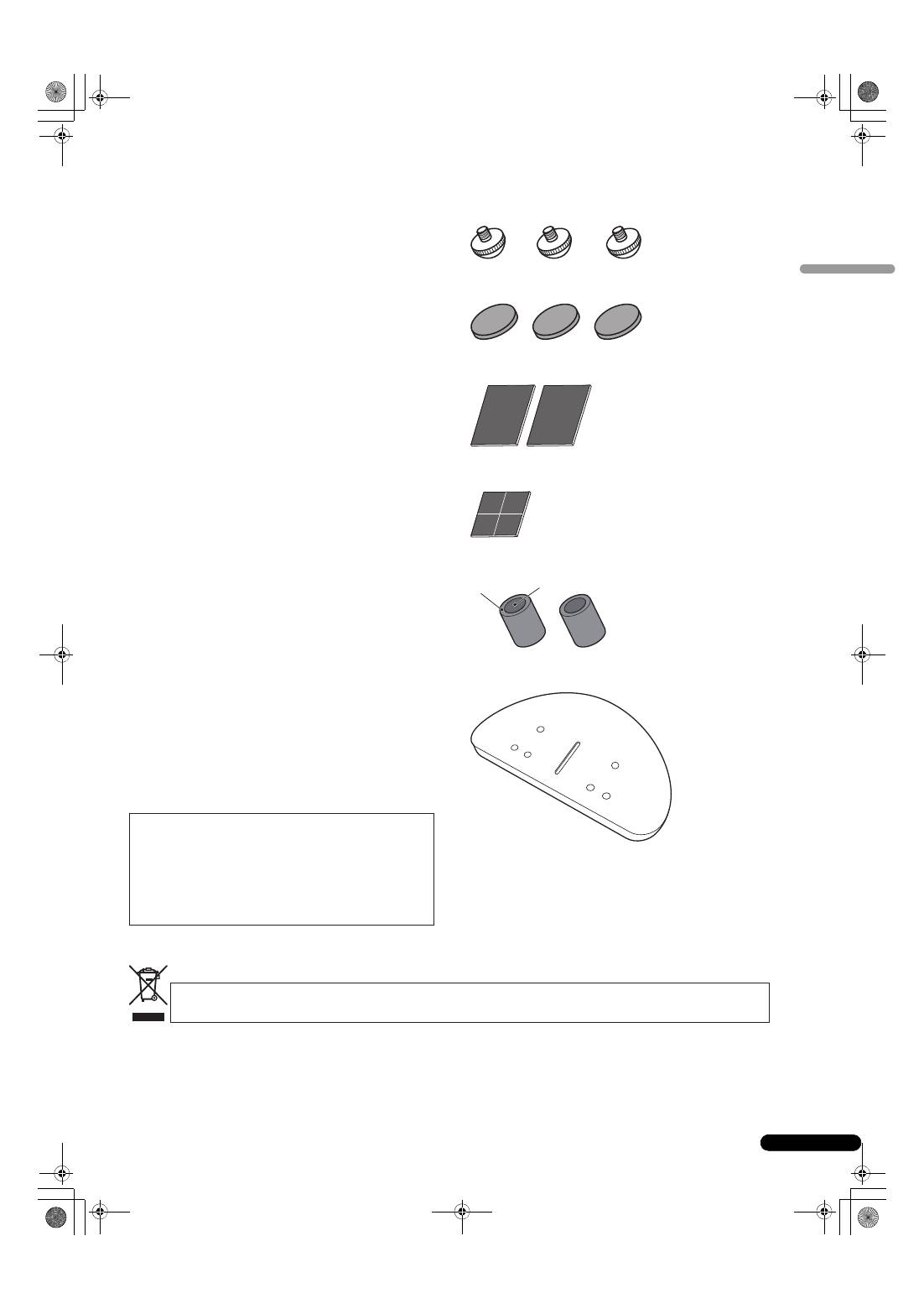
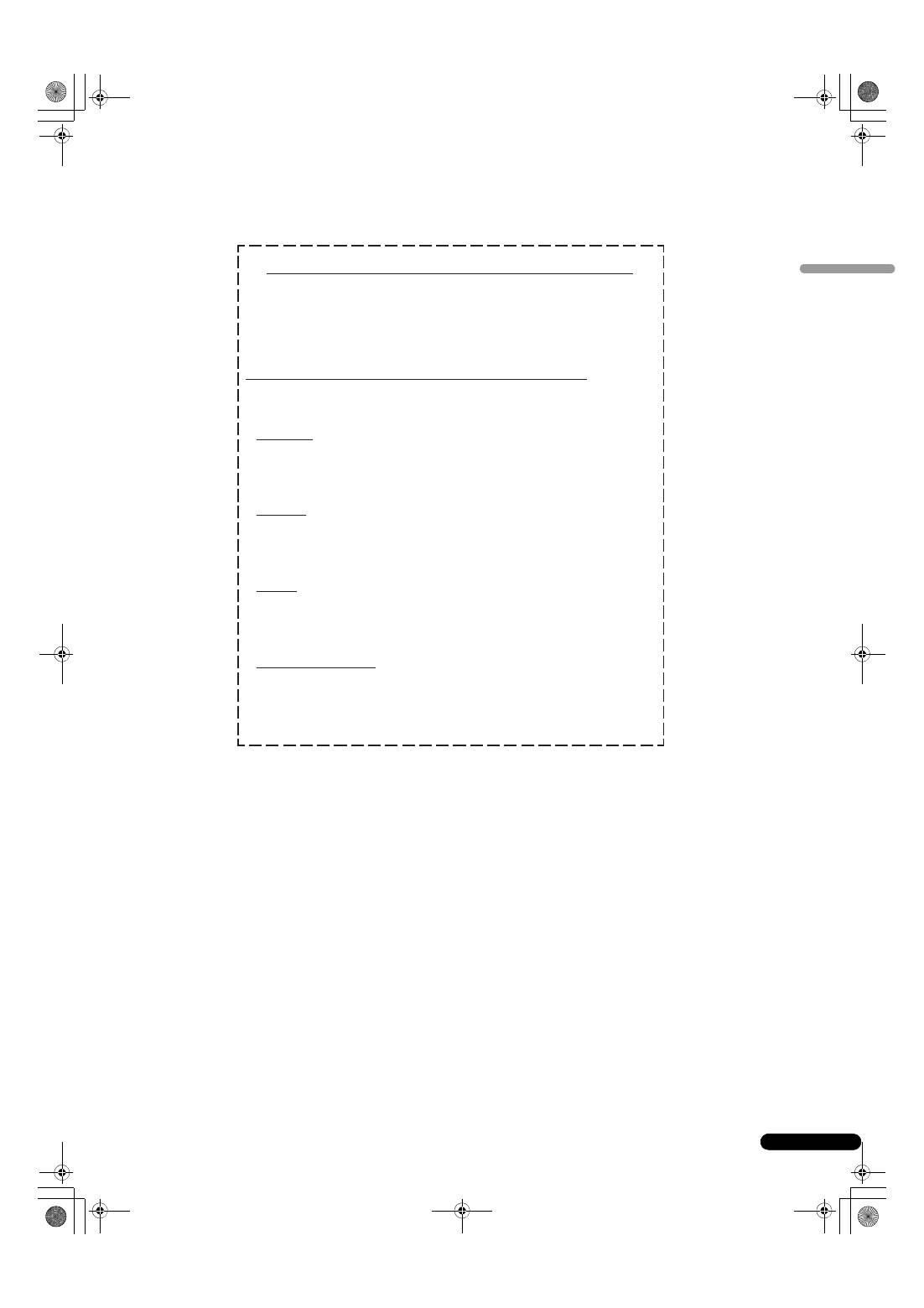
What’s in the box
Spikes x 3
Cork pads x 3
Large non-skid pads x 2
Small non-skid pads x 4
Foam plugs (A,B) x 2
Speaker base x 1
Washers x 2
Spring washer x 1
Screw (M5 x L40) x 1
Screws (M6 x L35) x 6
Grille x 1
Operating instructions
WARNING:
Handling the cord on this product or
cords associated with accessories sold with the
product will expose you to chemicals listed on
proposition 65 known to the State of California and
other governmental entities to cause cancer and
birth defect or other reproductive harm.
D36-P4_A_En
Wash hands after handling
If you want to dispose this product, do not mix it with general household waste. There is a separate collection system for used
electronic products in accordance with legislation that requires proper treatment, recovery and recycling.
Private households in the member states of the EU, in Switzerland and Norway may return their used electronic products free of charge to
designated collection facilities or to a retailer (if you purchase a similar new one).
For countries not mentioned above, please contact your local authorities for the correct method of disposal.
By doing so you will ensure that your disposed product undergoes the necessary treatment, recovery and recycling and thus prevent potential
negative effects on the environment and human health.
K058_A_En
A
B
S-8EX_EN.book 3 ページ 2008年7月16日 水曜日 午後2時20分
4
En
About the EX series
The EX series, incorporating the abundant technological know-how behind Pioneer’s flagship TAD speaker series, was developed
with the goal of creating the ultimate speaker possible in its price range.
The design and production of the EX series result from an international effort that represents the finest in Pioneer’s speaker technology.
Technology behind the S-8EX
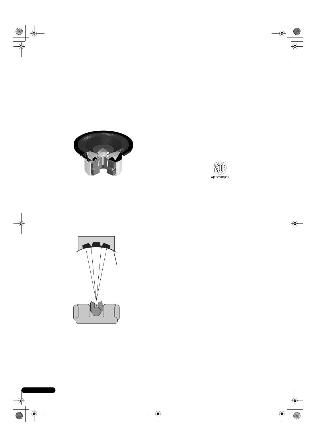
CST
The core driver of the system is the Coherent Source Transducer
(CST), which draws on the technology used in TAD. The tweeter
diaphragm is mounted concentrically within the apex of the
midrange cone and provides a point source of sound from
400 Hz to 100 kHz. The CST ensures a perfect spectral balance
between the direct and reflected sounds that arrive at the
listener’s ears, providing a more consistent sound throughout the
listening room and improved imaging capability.
Ceramic Graphite Diaphragm
The CST’s tweeter features a ceramic graphite diaphragm that
provides top-level strength and dampening characteristics that
are practically unrivaled by any other available materials currently
used in high-end audio speaker systems. Ceramic graphite’s
lightness and exceptional strength combine to create speakers
whose diaphragm resonance can be pushed far beyond their
audible range.
Magnesium Alloy Diaphragm
The CST’s midrange features a magnesium alloy diaphragm
whose characteristic lightness and high inner loss provide
excellent transience and minimal coloration of midrange sounds.
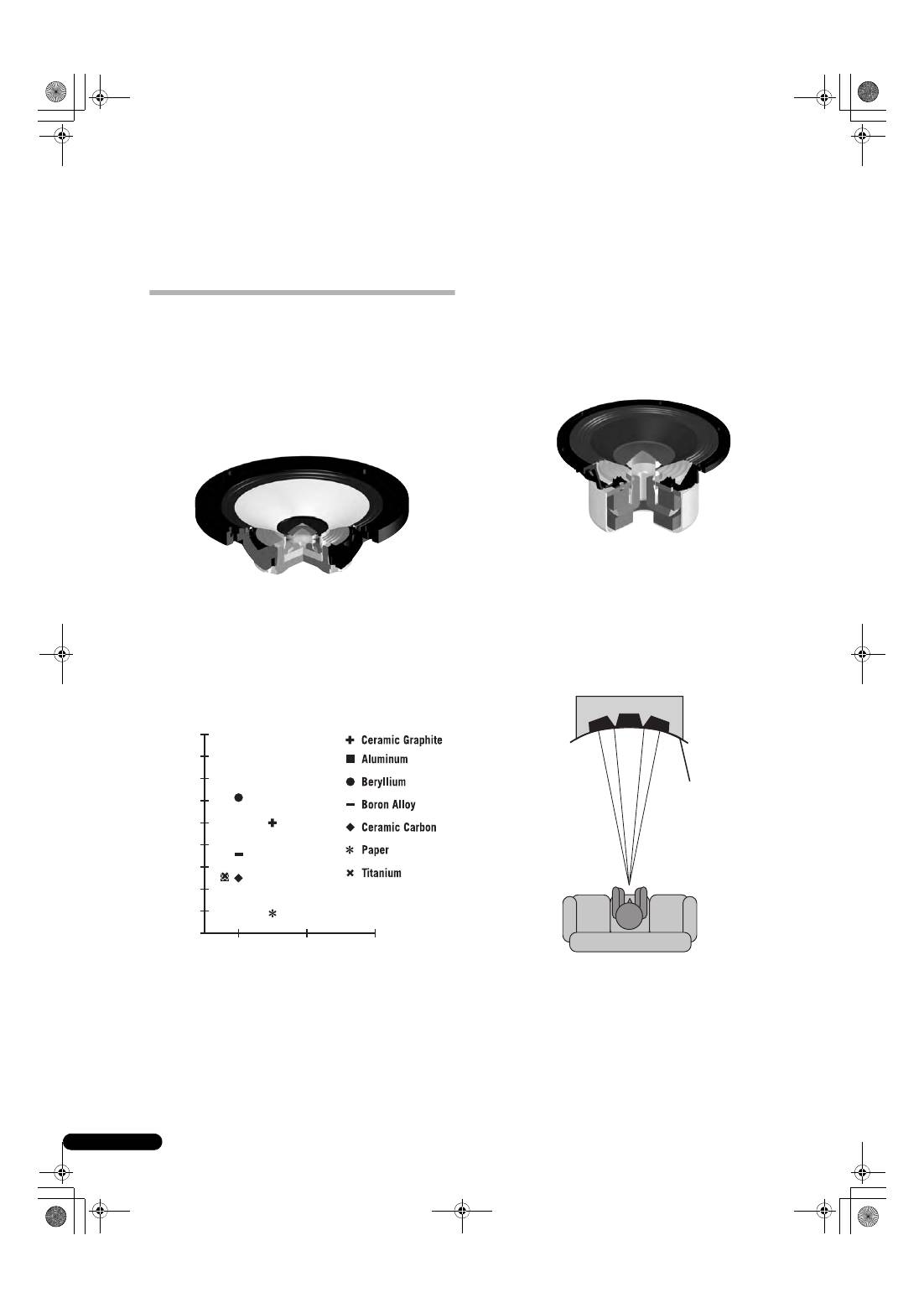
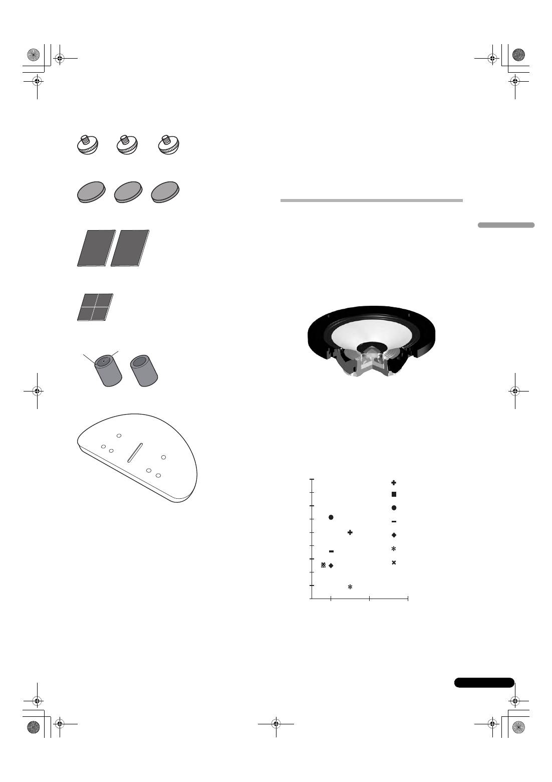
Bass Drivers
The bass driver pictured below serves as the foundation of the
S-8EX speaker system. The driver’s strength is the result of the
Aramid/Carbon composite material, originally created during the
development of the S-1EX, that is used in its diaphragm. Pioneer’s
exclusive LDMC magnetic circuit technology has been
incorporated in order to preserve linearity from low to high output
levels and minimize distortion.
Bass Enclosure Construction
The unique form of the S-8EX is based upon logical necessity. In
order to synchronize the arrival time of sound from the CST and
the two bass drivers, each driver is mounted upon a baffle that
serves to create a highly delicate curve known as the “precision
curve” (see illustration below). Made of up to 65 mm thick MDF
(Medium Density Fiberboard), this baffle is, moreover, strong
enough to contain the force of the drivers. Additionally, the bass
port has been carved out of an extremely thick block of MDF,
resulting in the reduction of wind noise for clear, deep bass.
18 000
Velocity (m/s)
Inner Loss
16 000
14 000
12 000
10 000
8 000
6 000
4 000
2 000
0.005
0.015
0.025
0
P
r
ecision cu
r
ve
S-8EX_EN.book 4 ページ 2008年7月16日 水曜日 午後2時20分
5
En
English
Crossover Networks
The crossover networks use only the finest components. Air cored
coils, noninductive resistors, and film capacitors in the signal path
are all carefully chosen and optimized for the CST driver to provide
the greatest transparency to the signal. The bass drivers use
silicon steel plate core inductors that minimize distortion and loss
during energy transfer. All components are connected directly to
their respective wiring materials, instead of a printed circuit-
board, allowing for minimal loss and maximum performance.
Collaboration with Air Studios
Since its establishment by George Martin in 1969, London,
England’s Air Studios has earned unequivocal respect from
scores of artists who recognize it as the world’s premier recording
studio. The Air Studios seal that was awarded to the S-8EX
indicates that these speakers are capable of producing the high-
quality sound demanded by the world’s top-class sound creators.
S-8EX_EN.book 5 ページ 2008年7月16日 水曜日 午後2時20分

6
En
Installation and Placement
How to install
Select a desired installation setup from the following.
When installing directly on the floor
Use the furnished spikes when installing the speaker directly on a
floor surface.
Installation
1
Twist the spikes into the threads of the three threaded
metal inserts (M6) embedded in the bottom of the speaker,
and screw down securely.
2
Set the cork pads in the positions where the points of the
three spikes will strike when the speaker is set down.
3
Set the speaker on top of the cork pads.
• As this unit weighs some 28 kg, it is very dangerous to try and
set the spike nut while tilting the speaker. Be sure to place the
unit on a soft area (such as a blanket) so that it does not
damage the floor, and carry out the installation with at least
two people.
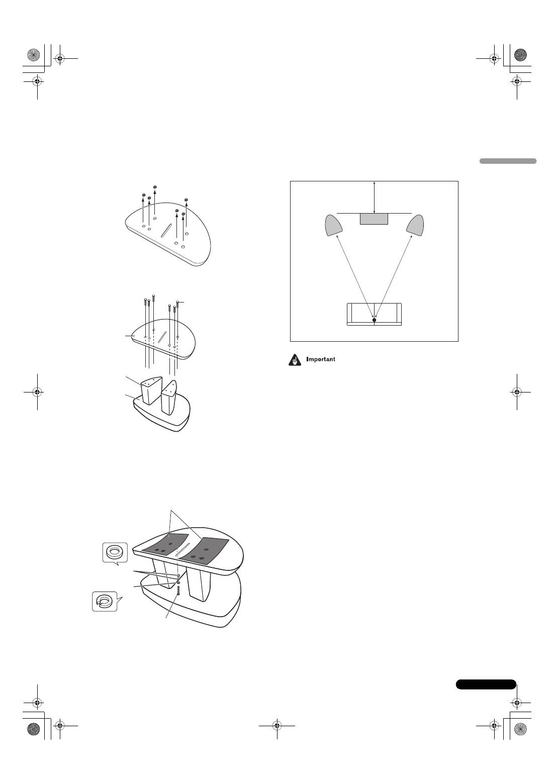
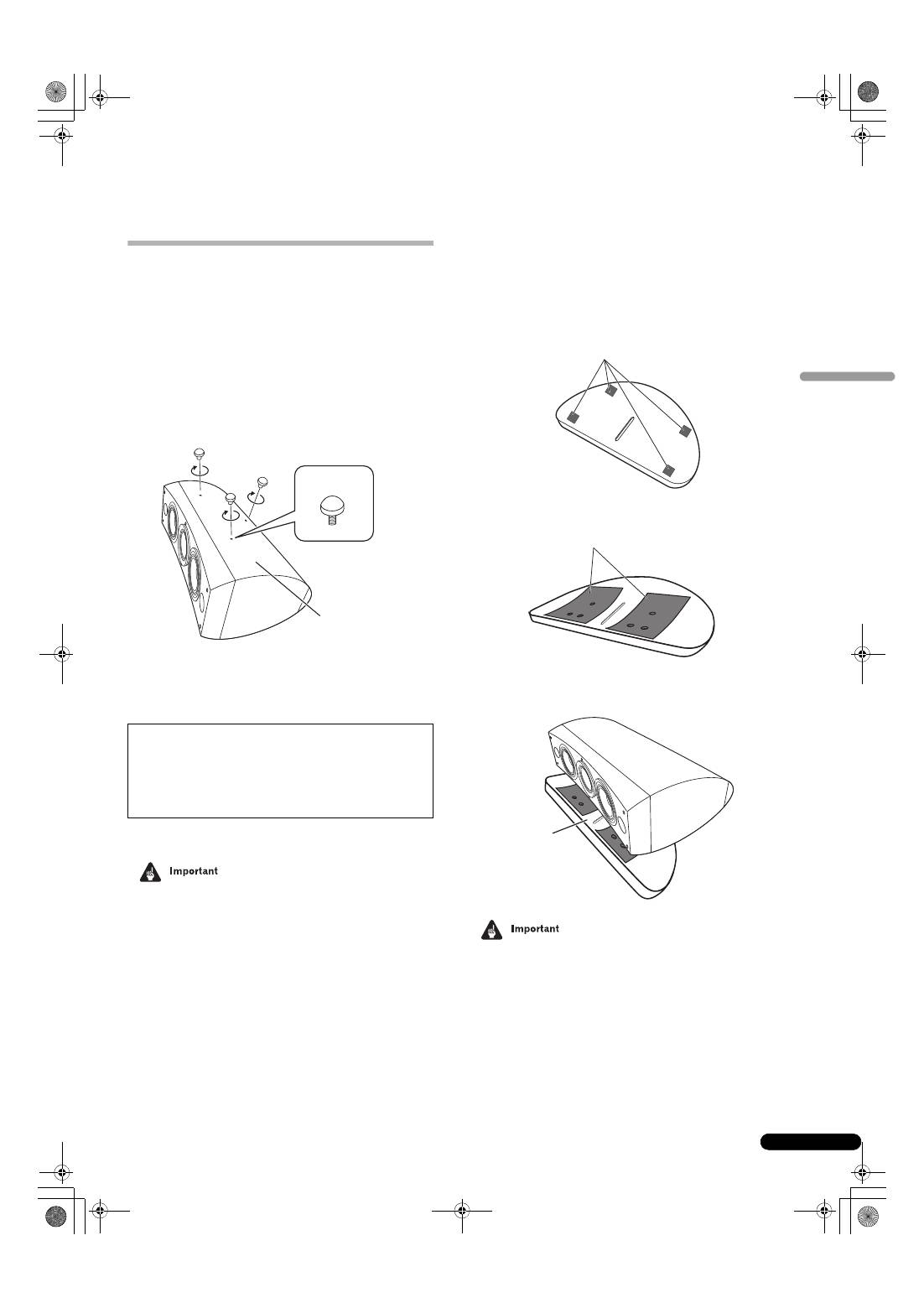
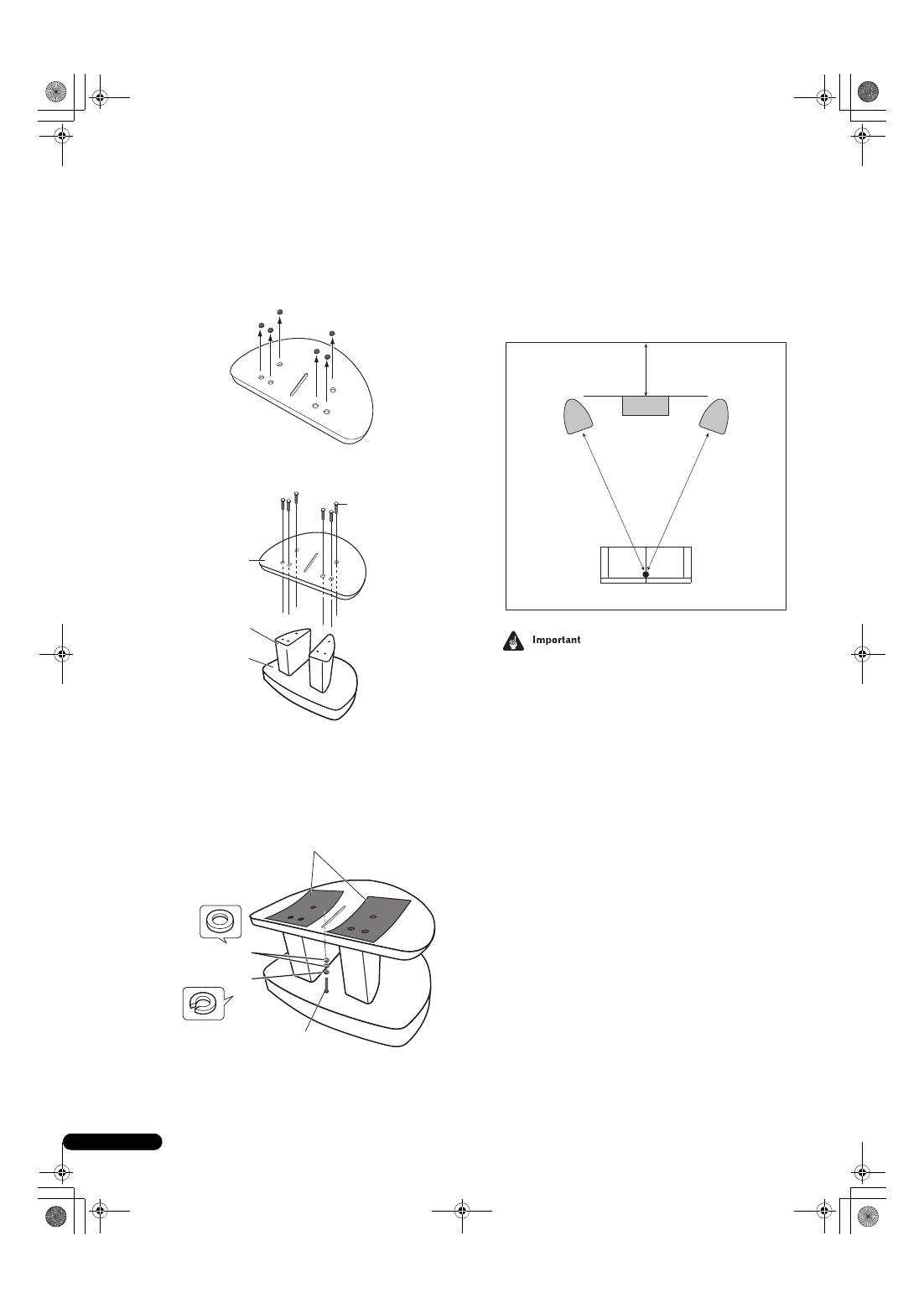
Using the furnished speaker base
When using the furnished speaker base, the use of the furnished
spikes is not required.
Installation
1
Affix the furnished non-skid pads (small) to the four
locations on the bottom of the base.
2
Affix the furnished non-skid pads (large) to the two
places on the top surface of the speaker base.
3
Place the speaker on top of the base.
Use of the furnished speaker base allows fine adjustment of
the speaker angle.
• When using the furnished speaker base, do not fix the speaker
in position with screws. The speaker may fall and cause injury.
If you do not use the cork pads when placing the
speakers, the spikes may cause damage to the floor. If
you plan on using the spikes we highly recommend to
use the cork pads.
Bottom of
speaker
Spike
Small non skid-
p
ads
La
r
ge non-skid
p
ads
S
p
eake
r
base
S-8EX_EN.book 6 ページ 2008年7月16日 水曜日 午後2時20分
7
En
English
Using the Pioneer Speaker Stand CP-7EX
To use the CP-7EX stand, the furnished speaker base needs to be
attached to the stand stems of the CP-7EX. Assemble the stands
as shown below.
Installation
1
Remove the packing material from the countersunk
screw holes in the speaker base.
2
Attach the speaker base to the stand stems of the CP-7EX.
Use only the furnished screws (M6 x L35).
3
Affix the non-skid pads (large).
4
Using the furnished screws (M5 x L40), spring washer and
washer, fasten the speaker to the stand.
To help ensure the speaker from falling, use only the provided
screws to fasten the speaker system to the speaker stand. For
details, consult the instructions provided with the CP-7EX
speaker stand.
Choosing Where To Place The Speaker Systems
Placement within the listening room will have a great impact upon
the total performance of the S-8EX speaker system in terms of
bass performance, tonal accuracy, and imaging. All rooms are
different and so this section is intended as a guide only.
Experimentation in your room will yield optimum results.
Use the graphic below as a guide to determine optimal speaker
placement.
.
• Do not place the speaker where it will be in direct sunlight, and
avoid positioning it near heaters and air conditioners. Doing
so may cause warping and discoloration of the speaker
cabinet and damage to the speaker.
• Pioneer assumes no liability whatsoever for damages
resulting from assembly, improper mounting, insufficient
reinforcement, misuse of the product, acts of nature, etc.
Sc
r
ews (M6 x L35)
S
p
eake
r
base
Stand stems
Stand base
CP-7EX
Sc
r
ew (M5 x L40)
La
r
ge non-skid
p
ads
Washe
r
s
S
pr
ing washe
r
Listening position
30 cm to 60 cm
Front
speaker
Center speaker
Front
speaker
S-8EX_EN.book 7 ページ 2008年7月16日 水曜日 午後2時20分
8
En
Connections
Connecting to an amplifier
This speaker does not include speaker cables used for connecting
to an amplifier. Take the following factors into consideration when
choosing speaker cables so that you can get the most from your
speaker system:
• Use heavy-gauge speaker cable if possible, and keep the
cables to the minimum necessary length.
• Cables have differing characteristics. Keep this in mind when
using any cable.
• Select cables with as little resistance as possible, and make
sure the cables to the speaker terminals and amp are firm and
secure.
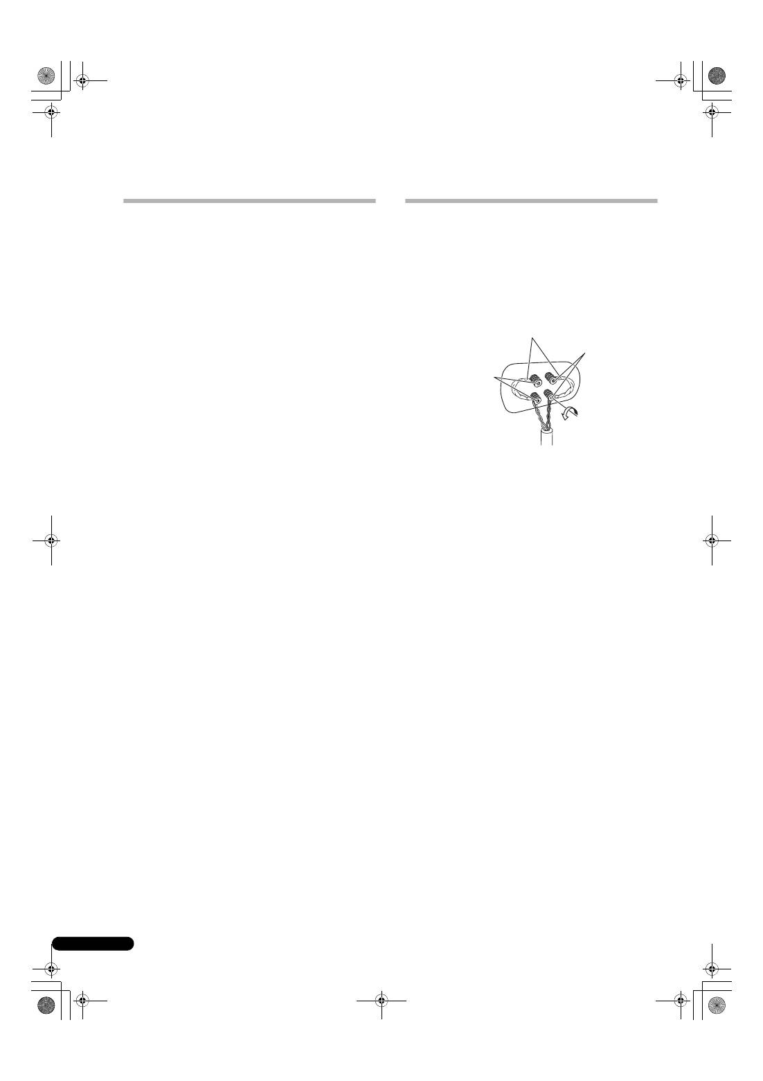
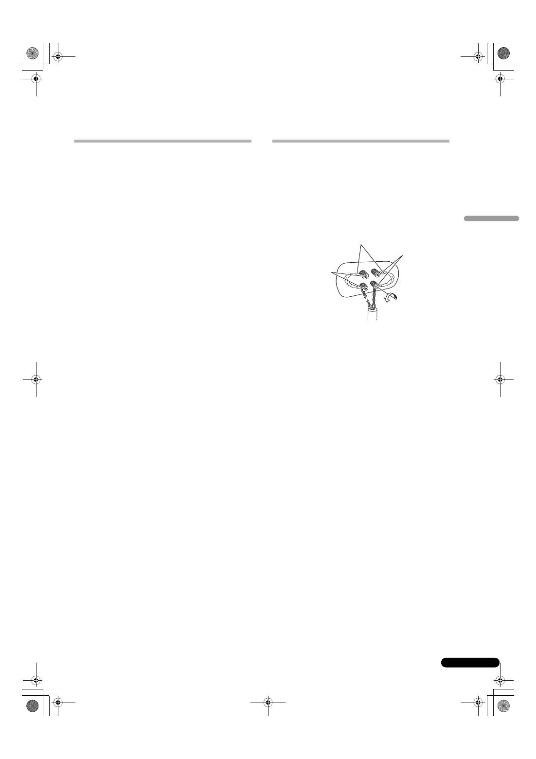
Connecting the cables
1
Switch off the power to your amplifier.
2
Connect the speaker cables to the input terminals (lower)
on the back of the speaker. For input terminal polarity, red is
positive (+) and black is negative (–).
3
Connect the other ends of the cables to the amp’s
speaker output terminals (for more details, refer to your amp
instruction manual).
• Grasp the cap knobs on the lower input terminals and rotate
them to the left (counter-clockwise), insert the speaker cable
wires into the holes in the terminal posts, then tighten the
knobs to secure the short bar as well as the wires.
• You can also connect the speaker’s terminals with a banana
plug. When using a banana plug, be sure to remove the cap at
the tip of the input terminal.
• After connecting the plugs, pull lightly on the cables to make
sure that the ends of the cables are securely connected to the
terminals. Poor connections can create noise and
interruptions in the sound.
• If the cables’ wires happen to be pushed out of the terminals,
allowing the wires to come into contact with each other, it
places an excessive additional load on the amp. This may
cause the amp to stop functioning, and may even damage the
amp.
CAUTION
These speaker terminals carry
HAZARDOUS LIVE
voltage
. To prevent the risk of electric shock when
connecting or disconnecting the speaker cables,
disconnect the power cord before touching any
uninsulated parts.
D3-4-2-2-3_A_En
Short bar connectors
Red terminal (+)
Black terminal
(–)
S-8EX_EN.book 8 ページ 2008年7月16日 水曜日 午後2時20分
9
En
English
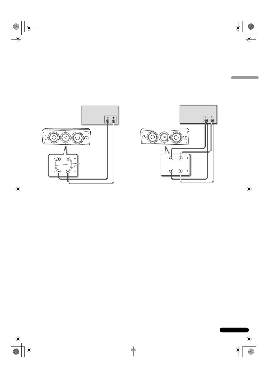
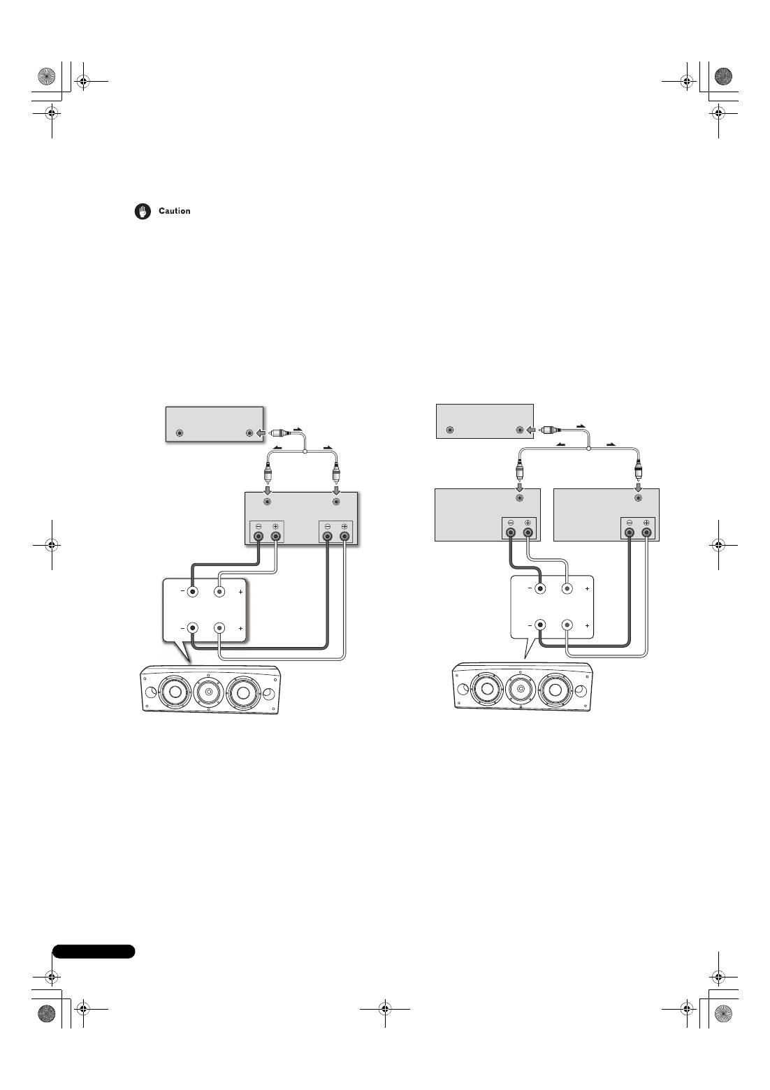
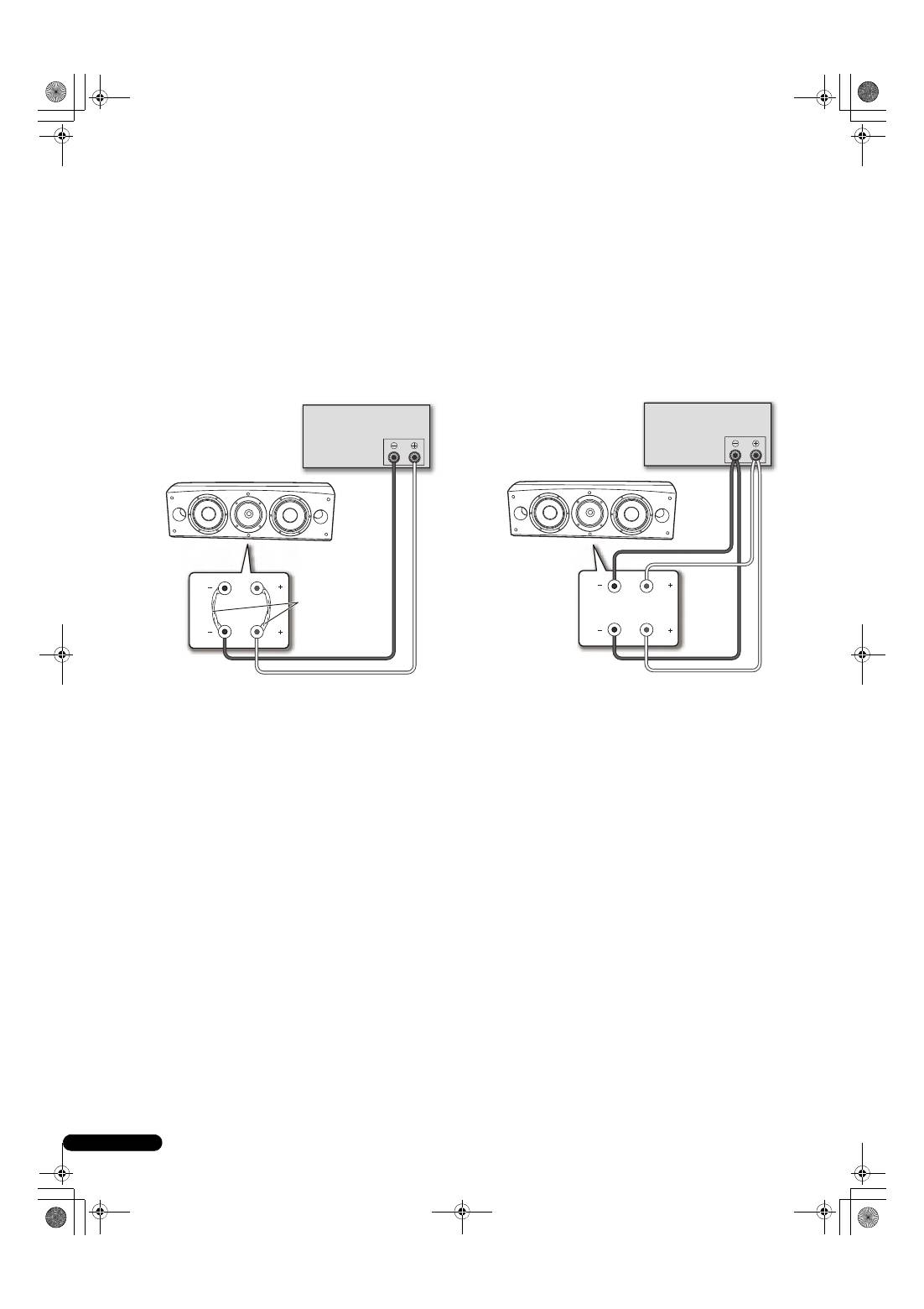
Single-Wire Connections
For single-wire connections, connect the mid-to-high- and low-
frequency sections of the crossover network with the shorting link
that was included with this unit, then connect the (+) wire from
your amplifier to either red binding post and the (–) wire from your
amplifier to either black binding post, as shown in below.
Bi-Wire Connections
In a bi-wiring connection, you independently plug in the speaker
systems running from the amp to their respective high- and low-
frequency plugs. This results in the CST driver and bass drivers
being independently connected directly to the amplifier, offering
you the freedom to optimize the cable type for each of the drivers.
Connect one set of wires to the bottom set of binding posts (bass
driver-specific network). Then connect a second set of wires to the
top binding posts (CST-specific network). Next, connect both sets
of wires to the appropriate terminals on your amplifier. Take care
to connect both (+) wires to the (+) amplifier terminals and both
(–) wires to the (–) amplifier terminals, as shown below.
SPEAKERS OUTPUT
Shorting link
connection
Speaker (rear): Input panel
Amplifier (rear)
(Only one channel shown)
Speaker
HF
HF
LF
LF
SPEAKERS OUTPUT
Speaker (rear): Input panel
Amplifier (rear)
(Only one channel shown)
Speaker
HF
HF
LF
LF
S-8EX_EN.book 9 ページ 2008年7月16日 水曜日 午後2時20分
10
En
Bi-Amplification Connections
Bi-Amplification allows the best performance when using dedicated amplifiers for low- and mid-to-high-frequency sections.
There are two possible configurations, commonly referred to as horizontal and vertical bi-amping.
Remove the shorting links before connecting speaker cables in bi-amplifications connections.
Failure to do so may result in damage to your amplifiers.
Vertical Bi-Amping
With this configuration, identical stereo amplifiers are used for
each speaker system. One channel of each amplifier drives the
low frequency section and the other channel drives the high
frequency section, as shown below.
Connect one set of wires and amplifier channel to the bottom set
of binding posts (bass driver-specific network).
Then connect a second set of wires and the other amplifier
channel to the top binding posts (CST-specific network).
Take care to connect both (+) wires to the (+) amplifier terminals
and both (–) wires to the (–) amplifier terminals.
Horizontal Bi-Amping
With this configuration, you may use different stereo amplifiers for
the low- and mid-to-high-frequency sections of the speaker system
(e.g., tube amplifiers for high frequency and solid state for low
frequency). Each channel of one amplifier drives the low-
frequency section of each speaker system and each channel of
the other amplifier drives the mid-to-high-frequency section, as
shown below.
This method requires that both amplifiers have the same gain;
otherwise an imbalance will be heard between the low- and mid-
to-high-frequency reproduction from the speaker system. If in
doubt, please consult your local dealer.
Speaker
SPEAKERS OUTPUT
INPUT
OUTPUT
INPUT
Ch.1
Ch.2
OUTPUT
Speaker (rear):
Input panel
(Only one channel shown)
Power amp
(rear)
(Commercially-
available Y-adaptor)
Pre-amp (rear)
HF
HF
LF
LF
SPEAKERS OUTPUT
INPUT
SPEAKERS OUTPUT
INPUT
OUTPUT
OUTPUT
Power amp (rear)
(Low frequency)
Power amp (rear)
(High frequency)
(Only one channel shown)
(Only one channel shown)
(Only one channel shown)
(Commercially-available
Y-adaptor)
Speaker (rear):
Input panel
Speaker
Pre-amp (rear)
HF
HF
LF
LF
S-8EX_EN.book 10 ページ 2008年7月16日 水曜日 午後2時20分
11
En
English
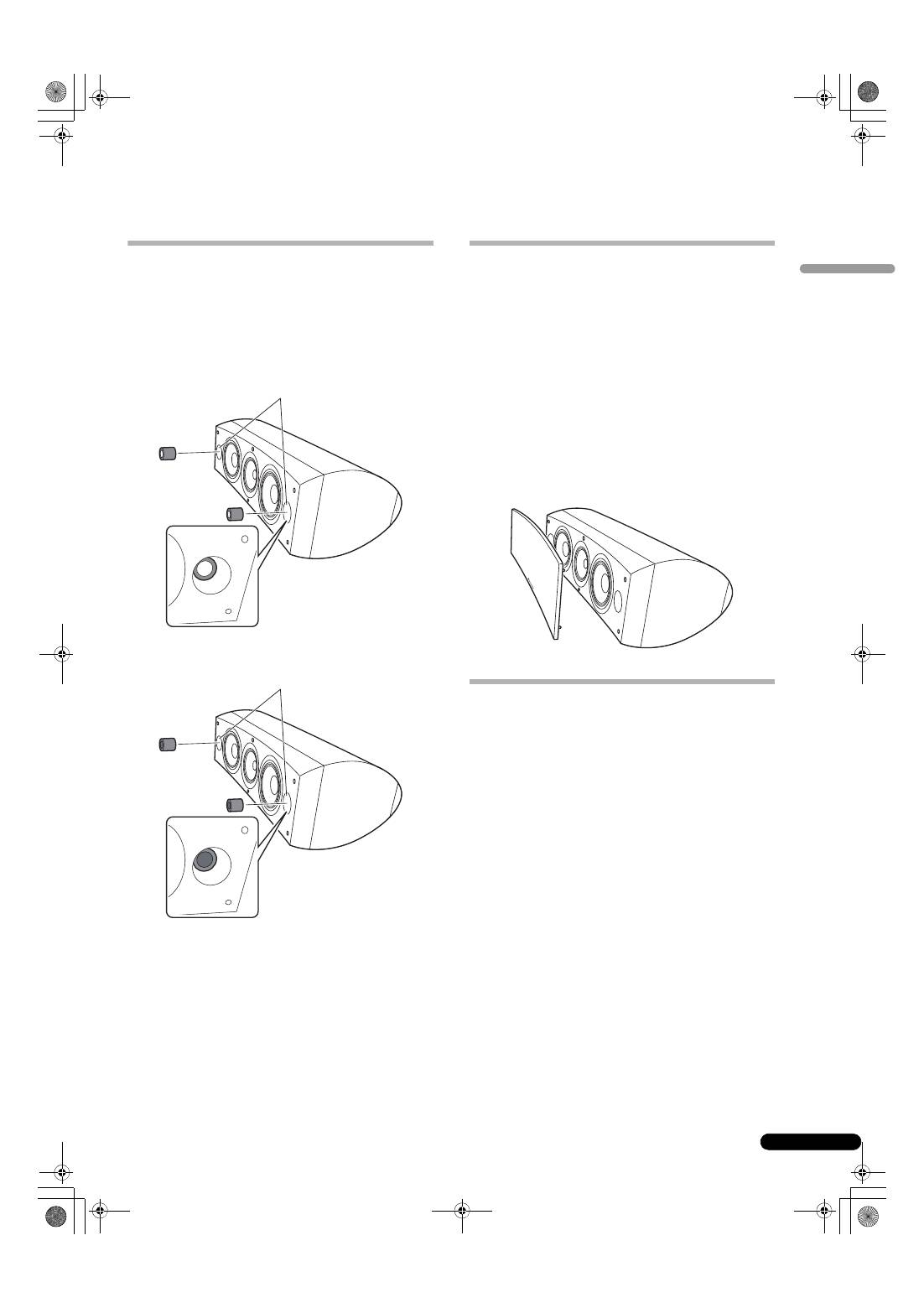
Other Information
Using the foam plugs
This unit is furnished with foam plugs that are useful for adjusting
the volume of bass sound. To use, place the foam plugs gently into
the bass reflex ports on either side of the speaker. Insert either
foam plug A alone, or both foam plugs A and B to achieve the
desired sound.
Using foam plugs A only
Using both foam plugs A and B
Attaching/Removing the Grille Cover
This speaker system comes with grille covers which may be
attached and removed by:
1
To attach the grille cover, line up the holes on the speaker
with the inserts on the grill, and press firmly.
2
To remove the grille cover, grasp the upper and lower
edges of the grille cover at the left side by your hands and
gently pull toward you to separate the left part of the grille
cover from the speaker.
3
Then move your hands to the middle of the grille cover
and again gently pull the upper and lower edges toward you
to separate the middle section.
4
Finally, grasp the upper and lower edges of the grille
cover at the right side and gently pull toward you to
separate the remaining part of the grille cover from the
speaker.
Cleaning the speaker cabinet
With normal use, wiping with a dry cloth should be sufficient to
keep the cabinet clean. If necessary, clean with a cloth dipped in
a neutral cleanser diluted five or six times with water, and wrung
out well. Do not use furniture wax or cleansers.
Never use thinners, benzine, insecticide sprays or other chemicals
on or near this unit since these will corrode the surfaces.
Bass
r
eflex
p
o
r
ts
Bass
r
eflex
p
o
r
ts
S-8EX_EN.book 11 ページ 2008年7月16日 水曜日 午後2時20分
12
En
Specifications
Enclosure . . . . . . . . . . . . . . . . . . . . . . . . Bass-reflex floorstanding type
(magnetically shielded)
Configuration . . . . . . . . . . . . . . . . . . . . . . . . . . . . . . . . . . . . . . . . . .3-way
Woofer . . . . . . . . . . . . . . . . . . . . . . . . . . . . . 16 cm (6
5
/
16
inch) cone x 2
Mid tweeter . . . . . . . . .14 cm (5
1
/
2
inch) cone/3 cm (1
3
/
16
inch) dome
Impedance . . . . . . . . . . . . . . . . . . . . . . . . . . . . . . . . . . . . . . . . . . . . . 6
Ω
Frequency response . . . . . . . . . . . . . . . . . . . . . . . . . . . .34 Hz to 100 kHz
Sensitivity . . . . . . . . . . . . . . . . . . . . . . . . . . . . . . . . . . . . 88.5 dB (2.83 V)
Maximum input power . . . . . . . . . . . . . . . . . . . . . . . . . . . . . . . . . . 160 W
Exterior dimensions . . . . . . . 723 (W) mm x 263 (H) mm x 387 (D) mm
28
1
/
2
(W) in. x 10
3
/
8
(H) in. x 15
1
/
4
(D) in.
Weight . . . . . . . . . . . . . . . . . . . . . . . . . . . . . . . . . . . . 28 kg (61 lbs 12 oz.)
Supplied accessories
Spikes . . . . . . . . . . . . . . . . . . . . . . . . . . . . . . . . . . . . . . . . . . . . . . . . . . . .3
Cork pads . . . . . . . . . . . . . . . . . . . . . . . . . . . . . . . . . . . . . . . . . . . . . . . . .3
Large non-skid pads . . . . . . . . . . . . . . . . . . . . . . . . . . . . . . . . . . . . . . . . .2
Small non-skid pads. . . . . . . . . . . . . . . . . . . . . . . . . . . . . . . . . . . . . . . . .4
Foam plugs (A,B) . . . . . . . . . . . . . . . . . . . . . . . . . . . . . . . . . . . . . . . . . . .2
Speaker base . . . . . . . . . . . . . . . . . . . . . . . . . . . . . . . . . . . . . . . . . . . . . .1
Washers . . . . . . . . . . . . . . . . . . . . . . . . . . . . . . . . . . . . . . . . . . . . . . . . . .2
Spring washer. . . . . . . . . . . . . . . . . . . . . . . . . . . . . . . . . . . . . . . . . . . . . .1
Screw (M5 x L40) . . . . . . . . . . . . . . . . . . . . . . . . . . . . . . . . . . . . . . . . . . .1
Screws (M6 x L35). . . . . . . . . . . . . . . . . . . . . . . . . . . . . . . . . . . . . . . . . . .6
Grille . . . . . . . . . . . . . . . . . . . . . . . . . . . . . . . . . . . . . . . . . . . . . . . . . . . . .1
Operating instructions
Specifications and design subject to possible modification
without notice, due to improvements.
Magnetic shielding
This speaker system is magnetically shielded. However,
depending on the installation location, color distortion may occur
if the speaker system is installed extremely close to the screen of
a television set.
If this happens, turn off the television, then turn it on again after
15 min to 30 min. If the problem persists, place the speaker system
away from the television set.
is a trademark placed on a product with Pioneer’s Phase
Control technology. This technology enables high-grade sound
reproduction through each component by improving overall
phase matching.
Published by Pioneer Corporation.
Copyright © 2008 Pioneer Corporation.
All rights reserved.
S-8EX_EN.book 12 ページ 2008年7月16日 水曜日 午後2時20分
13
En
English
AFTER-SALES SERVICE FOR PIONEER PRODUCTS
Please contact the dealer or distributor from where you purchased the
product for its after-sales service (including warranty conditions) or any
other information. In case the necessary information is not available,
please contact the Pioneer’s subsidiaries (regional service headquarters)
listed below:
PLEASE DO NOT SHIP YOUR PRODUCT TO THE COMPANIES at the
addresses listed below for repair without advance contact, for these
companies are not repair locations.
AMERICA
PIONEER ELECTRONICS SERVICE, INC.
P.O. BOX 1760, LONG BEACH, CA 90801-1760, U.S.A.
CUSTOMER SERVICE HOTLINE : 1 (800) 421-1404
EUROPE
PIONEER EUROPE NV
EUROPEAN SERVICE DIVISION
HAVEN 1087, KEETBERGLAAN 1, B-9120 MELSELE, BELGIUM
ASEAN
PIONEER ELECTRONICS ASIACENTRE PTE. LTD.
SERVICE DEPARTMENT
253, ALEXANDRA ROAD #04-01 SINGAPORE 159936
JAPAN AND OTHERS
PIONEER CORPORATION (HEAD OFFICE)
CUSTOMER SUPPORT CENTER
4-1, MEGURO 1-CHOME, MEGURO-KU, TOKYO 153-8654 JAPAN
S016_A_En
S-8EX_EN.book 13 ページ 2008年7月16日 水曜日 午後2時20分
2
Fr
Nous vous remercions d’avoir acheté ce produit Pioneer.
Veuillez lire attentivement ce mode d’emploi de manière à pouvoir utiliser votre modèle correctement.
Après avoir lu ces explications, conservez-les en lieu sûr pour éventuellement les consulter plus tard.
Sommaire
Avant de commencer
Contenu de l’emballage
A propos de la série EX
Technologies à l’appui du S-8EX
. . . . . . . . . . . . . . . . . . . . . . . . . . . 3
CST
. . . . . . . . . . . . . . . . . . . . . . . . . . . . . . . . . . . . . . . . . . . . . . . . 3
Diaphragme en graphite céramique
. . . . . . . . . . . . . . . . . . . . . . . 3
Diaphragme en alliage de magnésium
. . . . . . . . . . . . . . . . . . . . . 4
Haut-parleurs de graves
. . . . . . . . . . . . . . . . . . . . . . . . . . . . . . . . 4
Construction du boîtier des graves
. . . . . . . . . . . . . . . . . . . . . . . . 4
Circuits séparateurs de fréquences
. . . . . . . . . . . . . . . . . . . . . . . 4
Collaboration avec Air Studios
. . . . . . . . . . . . . . . . . . . . . . . . . . . 4
Installation et placement
Méthode d’installation
. . . . . . . . . . . . . . . . . . . . . . . . . . . . . . . . . . 5
Pour une installation directement sur le plancher
. . . . . . . . . . . . 5
Utilisation de la base d’enceinte fournie
. . . . . . . . . . . . . . . . . . . . 5
Utilisation du Socle d’enceinte Pioneer CP-7EX
. . . . . . . . . . . . . . 6
Choix d’un emplacement pour les enceintes acoustiques
. . . . . . 6
Connexions
Branchement à un amplificateur
. . . . . . . . . . . . . . . . . . . . . . . . . . 7
Câblage
. . . . . . . . . . . . . . . . . . . . . . . . . . . . . . . . . . . . . . . . . . . . . . 7
Mono-câblage
. . . . . . . . . . . . . . . . . . . . . . . . . . . . . . . . . . . . . . . . 8
Bi-câblage
. . . . . . . . . . . . . . . . . . . . . . . . . . . . . . . . . . . . . . . . . . 8
Câblage pour bi-amplification
. . . . . . . . . . . . . . . . . . . . . . . . . . . . 9
Autres informations
Utilisation des bouchons de mousse
. . . . . . . . . . . . . . . . . . . . . . . 10
Utilisation des bouchons de mousse A seulement
. . . . . . . . . . . 10
Utilisation des bouchons de mousse A et B
. . . . . . . . . . . . . . . . 10
Fixation et dépose du couvercle de grille
. . . . . . . . . . . . . . . . . . . . 10
Nettoyage du coffret de l’enceinte
. . . . . . . . . . . . . . . . . . . . . . . . . 10
Fiche technique
. . . . . . . . . . . . . . . . . . . . . . . . . . . . . . . . . . . . . . 11
Avant de commencer
• L’impédance nominale de ces enceintes acoustiques est de
6
Ω
. Raccordez ces enceintes à un amplificateur dont
l’impédance de charge va de 6
Ω
à 16
Ω
(un modèle pour
lequel “6
Ω
– 16
Ω
” est indiqué sur les bornes de sortie de
haut-parleurs).
Pour éviter d’endommager les enceintes par une surcharge à
l’entrée, observez les précautions suivantes :
• Ne fournissez pas aux enceintes acoustiques une puissance
électrique dépassant l’entrée maximale autorisée.
• Si vous utilisez un égaliseur graphique pour accentuer les
sons dans la plage des hautes fréquences, n’élevez pas trop le
volume de l’amplificateur.
• N’essayez pas de pousser un amplificateur de faible
puissance à produire un volume sonore élevé, car la distorsion
harmonique de l’amplificateur en serait accentuée et vous
pourriez endommager les haut-parleurs.
Précautions installation
• Lors de l’installation de l’appareil, veillez à ce qu’il soit
fermement immobilisé et évitez les endroits d’où il pourrait
tomber et provoquer des blessures lors d’une catastrophe
naturelle, telle qu’un séisme.
• Ne fixez pas les enceintes sur une paroi ou au plafond, car
elles pourraient tomber et provoquer des blessures.
• N’installez pas les enceintes en hauteur, au plafond ou sur
une paroi. Si elle est mal installée, la grille des haut-parleurs
pourrait tomber et provoquer des dégâts, voire des blessures
à des personnes.
• Mettez votre système audiovisuel hors tension et débranchez-
le, puis consultez le mode d’emploi avant de brancher des
composants. Prenez soin d’utiliser correctement les cordons
de raccordement.
Précautions à l’emploi
• Ne placez pas l’enceinte sur une surface instable, car en
tombant, elle pourrait entraîner des blessures et être
endommagée.
• N’utilisez pas les enceintes pour produire des sons distordus
pendant une longue période, car ceci pourrait provoquer un
incendie.
• Ne montez pas et ne vous asseyez pas sur les enceintes et ne
laissez pas des enfants jouer sur celles-ci.
• Ne posez pas d’objets lourds ou volumineux sur le dessus des
enceintes.
• Ne placez pas d’objets magnétiques tels que des tournevis ou
des pièces en fer près du tweeter ou du médium. Comme ces
haut-parleurs utilisent des aimants puissants, ces objets
pourraient être attirés, provoquant des dégâts aux haut-
parleurs ou endommageant leur diaphragme.
K058_A_Fr
Si vous souhaitez vous débarrasser de cet appareil, ne le mettez pas à la poubelle avec vos ordures ménagères. Il existe un système de
collecte séparé pour les appareils électroniques usagés, qui doivent être récupérés, traités et recyclés conformément à la législation.
Les habitants des états membres de l’UE, de Suisse et de Norvège peuvent retourner gratuitement leurs appareils électroniques usagés aux
centres de collecte agréés ou à un détaillant (si vous rachetez un appareil similaire neuf).
Dans les pays qui ne sont pas mentionnés ci-dessus, veuillez contacter les autorités locales pour savoir comment vous pouvez vous débarrasser
de vos appareils.
Vous garantirez ainsi que les appareils dont vous vous débarrassez sont correctement récupérés, traités et recyclés et préviendrez de cette façon
les impacts néfastes possibles sur l’environnement et la santé humaine.
S-8EX_FR.book 2 ページ 2008年7月16日 水曜日 午後2時21分
3
Fr
Français
Contenu de l’emballage
Pointes de découplage x 3
Cales en liège x 3
Grands coussinets antidérapants x 2
Petits coussinets antidérapants x 4
Bouchons de mousse (A, B) x 2
Base d’enceinte x 1
Rondelles x 2
Rondelle à ressort x 1
Vis (M5 x L40) x 1
Vis (M6 x L35) x 6
Grille x 1
Mode d’emploi
A propos de la série EX
Tirant parti du riche savoir-faire technologique qui a permis
de créer la série-phare d’enceintes acoustiques TAD de
Pioneer, la série EX a été mise au point afin de proposer ce
qu’il y a de mieux dans cette catégorie de prix.
Le design et la production de la série EX résultent d’un effort
international qui a fait converger la quintessence des
technologies de Pioneer dans le domaine des haut-parleurs.
Technologies à l’appui du S-8EX
CST
L’excitateur électrostatique au cœur du système est le
Transducteur de Source Cohérent (CST) qui repose sur les
technologies utilisées dans la série TAD. Le diaphragme du
tweeter est installé de façon concentrique au sommet du cône du
médium et il fournit une source ponctuelle de sons, allant de
400 Hz à 100 kHz. Le transducteur CST procure un équilibre
spectral parfait entre les sons directs et réfléchis qui parviennent
aux oreilles de l’auditeur. Il fournit ainsi un son plus homogène
dans toute la salle d’écoute et améliore l’image sonore.
Diaphragme en graphite céramique
Le tweeter du CST est muni d’un diaphragme en graphite
céramique qui procure des caractéristiques idéales de rigidité et
d’amortissement. Elles atteignent un niveau pratiquement
inégalable par les autres matériaux actuellement disponibles pour
les enceintes acoustiques haut de gamme. La légèreté et la
résistance exceptionnelles du graphite céramique s’associent
pour créer des haut-parleurs dont la résonance de diaphragme
peut être poussée bien au-delà de leur plage audible.
A
B
Graphite céramique
Aluminium
Beryllium
Alliage de boron
Carbone céramique
Papier
Titane
18 000
Vélocité (m/s)
Pertes internes
16 000
14 000
12 000
10 000
8 000
6 000
4 000
2 000
0,005
0,015
0,025
0
S-8EX_FR.book 3 ページ 2008年7月16日 水曜日 午後2時21分
4
Fr
Diaphragme en alliage de magnésium
Le haut-parleur médium du CST présente un diaphragme en
alliage de magnésium dont la légèreté et la forte perte interne
assurent une excellente transition et une coloration minimale des
sons de la plage moyenne.
Haut-parleurs de graves
Le haut-parleur de graves illustré ci-dessous sert de base à
l’enceinte acoustique S-8EX. La rigidité de sa membrane provient
du matériau composite en aramide/carbone, créé lors de la mise
au point du S-1EX et utilisé dans son diaphragme. La technologie
des circuits magnétiques LDMC, exclusive à Pioneer, a été
intégrée afin de réduire la distorsion et de préserver la linéarité à
tous les niveaux de sortie, des faibles aux puissants.
Construction du boîtier des graves
La forme unique du S-8EX a une fonction bien précise. Afin de
synchroniser les temps d’arrivée des sons provenant du CST et
des deux haut-parleurs de graves, chacun d’eux est installé sur un
baffle qui contribue à créer une courbe très délicate, appelée la
“courbe de précision” (cf. L’illustration ci-dessous). Réalisé en
MDF (Medium Density Fiberboard) d’une épaisseur allant jusqu’à
65 mm, ce baffle est par ailleurs suffisamment rigide pour
contenir la force des hautparleurs. De plus, le port des graves est
découpé dans un bloc extrêmement épais de MDF, ce qui réduit
les bruits de vent et fournit des graves profondes et claires.
Circuits séparateurs de fréquences
Les circuits séparateurs de fréquences n’utilisent que des
composants hors pair. Disposés sur le parcours des signaux, des
bobines à air, des résistances non inductives et des
condensateurs à film ont été choisis et optimisés avec soin de
sorte que le CST puisse procurer la plus grande transparence
possible aux signaux. Les haut-parleurs de graves font appel à des
inducteurs à noyau en plaque d’acier au silicium pour minimiser
la distorsion et les pertes pendant le transfert d’énergie. Tous les
composants sont reliés directement à leurs matériaux de câblage
respectifs et non pas à une carte de circuit imprimé, ce qui
autorise des pertes minimales et des performances maximales.
Collaboration avec Air Studios
Depuis leur fondation à Londres par George Martin en 1969, les Air
Studios d’Angleterre se sont acquis le respect sans aucun
équivoque d’une foule d’artistes qui les considèrent comme les
meilleurs studios d’enregistrement au monde. Le label “Air
Studios” décerné aux S-8EX prouve que ces enceintes
acoustiques sont capables de restituer la haute qualité sonore,
exigée par les ingénieurs du son les plus réputés du monde.
Coube de
pr
écision
S-8EX_FR.book 4 ページ 2008年7月16日 水曜日 午後2時21分
5
Fr
Français
Installation et placement
Méthode d’installation
Sélectionnez un mode d’installation en tenant compte de ce qui
suit.
Pour une installation directement sur le plancher
Utilisez les pointes de découplage fournie pour installer
directement l’enceinte sur un plancher.
Installation
1
Insérez les pointes dans le filetage des trois
encastrements métalliques filetés (M6), prévus sur le fond de
l’enceinte, et vissez les pointes à fond.
2
Fixez les cales de liège aux positions ou les pointes de
découplage feront contact lorsque l’enceinte sera posée à
plat.
3
Placez l’enceinte sur le dessus des coussinets de liège.
• Comme l’appareil pèse environ 28 kg, il est dangereux
d’essayer d’ajuster l’écrou de la pointe de découplage en
inclinant l’enceinte. Posez l’appareil sur une surface douce,
telle qu’une couverture, de sorte qu’elle n’abîme pas le
plancher et procédez à deux personnes au moins pour
effectuer l’installation.
Utilisation de la base d’enceinte fournie
A l’emploi du socle d’enceinte fourni, il n’est pas nécessaire
d’utiliser les pointes de découplage fournies.
Installation
1
Fixez les (petits) coussinets antidérapants fournis aux
quatre endroits sur le fond de la base.
2
Fixez les (grands) coussinets antidérapants fournis aux
deux endroits sur le dessus du socle d’enceinte.
3
Placez l’enceinte sur le dessus de la base.
L’emploi de la base d’enceinte fournie autorise un ajustement
précis de l’angle de l’enceinte.
• A l’emploi du socle d’enceinte fourni, n’immobilisez pas
l’enceinte avec les vis. L’enceinte pourrait tomber et causer
des blessures.
Si vous n’utilisez pas les cales de liège à l’installation
des enceintes, les pointes de découplage risquent
d’endommager le plancher. Si vous prévoyez
d’employer les pointes de découplage, nous
conseillons vivement d’utiliser leurs coussinets de
liège.
Fond d’enceinte
Pointe de
découplage
Petits coussinets antidé
r
a
p
ants
G
r
ands coussinets antidé
r
a
p
ants
Base
d’enceinte
S-8EX_FR.book 5 ページ 2008年7月16日 水曜日 午後2時21分
6
Fr
Utilisation du Socle d’enceinte Pioneer CP-7EX
Pour utiliser le socle CP-7EX, la base d’enceinte fournie doit être
fixée sur les tiges du socle CP-7EX. Assemblez le socle comme
illustré ci-dessous.
Installation
1
Enlevez le matériau d’emballage hors des trous de vis à
tête fraisée, prévus sur la base de l’enceinte.
2
Fixez la base d’enceinte sur les tiges du socle CP-7EX.
Utilisez uniquement les vis fournies (M6 x L35).
3
Fixez les (grands) coussinets antidérapants.
4
Au moyen des vis fournies (M5 x L40), de la rondelle à
ressort et de la rondelle, fixez l’enceinte sur le socle.
Pour éviter une chute de l’enceinte, utilisez uniquement les vis
fournies lorsque vous fixez l’enceinte sur son socle. Pour des
détails, consultez les instructions fournies avec le socle
d’enceinte CP-7EX.
Choix d’un emplacement pour les enceintes
acoustiques
L’emplacement des enceintes dans votre salle d’écoute aura une
grande répercussion sur les qualités d’ensemble de la S-8EX en
terme de performances des graves, d’image sonore et de
précision tonale. Tous les locaux sont différents et cette section ne
peut donc prétendre qu’à servir de guide. C’est en procédant à
diverses expérimentations que vous obtiendrez les meilleurs
résultats.
Utilisez le graphique suivant comme guide pour déterminer
l’emplacement idéal des enceintes.
.
• N’installez pas les enceintes en plein soleil et évitez de les
placer près d’appareils de chauffage ou de climatiseurs, car
ceci pourrait gondoler et décolorer le coffret des enceintes et
endommager leurs haut-parleurs.
• Pioneer n’assume aucune responsabilité en cas de dégâts
causés par un assemblage et un montage inadéquats, un
renforcement insuffisant, une erreur d’utilisation, des
catastrophes naturelles, etc.
Vis (M6 x L35)
Base
d’enceinte
Montants de socle
Base de socle
CP-7EX
Vis (M5 x L40)
G
r
ands coussinets antidé
r
a
p
ants
Rondelles
Rondelle à
r
esso
r
t
30 cm à 60 cm
Enceinte
avant
Enceinte
avant
Enceinte centrale
Position d’écoute
S-8EX_FR.book 6 ページ 2008年7月16日 水曜日 午後2時21分
7
Fr
Français
Connexions
Branchement à un amplificateur
Les câbles d’enceintes, nécessaires pour le branchement à un
ampli, ne sont pas fournis avec cette enceinte acoustique. Tenez
compte des facteurs suivants lorsque vous choisissez les câbles
d’enceinte, de manière à obtenir des performances idéales de vos
enceintes acoustiques :
• Si possible, utilisez des câbles d’enceinte de gros calibre et
d’une longueur minimale.
• Les câbles ont chacun des caractéristiques différentes. Tenez
compte de ce point lorsque vous les choisissez.
• Sélectionnez des câbles dont la résistance est la moindre
possible et veillez à ce que les connexions des câbles soient
solides sur les enceintes et sur l’amplificateur.
Câblage
1
Mettez l’amplificateur hors tension.
2
Branchez les câbles d’enceinte sur les bornes d’entrée
(inférieures) à l’arrière de l’enceinte. En ce qui concerne les
polarités des bornes, la rouge est positive (+) et la noire est
négative (–).
3
Raccordez l’autre bout des câbles sur les bornes de sortie
d’enceinte de l’amplificateur (pour plus d’informations,
consultez le mode d’emploi de votre amplificateur).
• Saisissez le bouton-capuchon sur les bornes d’entrée
inférieure et tournez-le vers la gauche (sens antihoraire),
insérez les fils du câble d’enceinte dans l’orifice du montant
de borne, puis tournez le bouton pour immobiliser les fiches
coupe-circuit et les fils.
• Vous pouvez également utiliser une fiche banane pour cette
connexion. Dans ce cas, vous devrez d’abord déposer le
capuchon présent sur le bouton de la borne d’entrée.
• Après avoir branché les câbles sur les bornes, tirez
légèrement sur ceux-ci pour vous assurer que leur extrémité
est parfaitement immobilisée sur les bornes. De mauvaises
connexions sont la source de parasites, voire d’interruption
des sons.
• Si les fils des câbles ressortent des bornes et s’ils entrent en
contact mutuellement, l’amplificateur subira une charge
additionnelle, ce qui peut l’obliger à s’arrêter, voire
l’endommager.
ATTENTION
Les bornes des haut-parleurs sont sous une
tension
ACTIVE DANGEREUSE
. Pour éviter tout risque de
décharge électrique lors du branchement et du
débranchement des câbles de haut-parleur, débranchez
le cordon d’alimentation avant de toucher des parties
non isolées.
D3-4-2-2-3_A_Fr
Connexion de fiche coupe-circuit
Borne rouge (+)
Borne noire
(–)
S-8EX_FR.book 7 ページ 2008年7月16日 水曜日 午後2時21分
8
Fr
Mono-câblage
Pour les connexions en mono-câblage, raccordez les sections
médium-hautes et basses fréquences du circuit séparateur de
fréquences au moyen d’une fiche coupe-circuit, fournie avec cet
appareil, puis raccordez le câble (+) de votre amplificateur à la
borne de connexion rouge et le câble (–) de votre amplificateur sur
la borne de connexion noire, comme illustré ci-après.
Bi-câblage
Lors d’une connexion en bi-câblage, vous branchez
indépendamment les enceintes, provenant de l’amplificateur, sur
leurs fiches haute fréquence et basse fréquence respectives. Le
CST et les haut-parleurs de graves sont ainsi indépendamment
raccordés directement sur l’amplificateur, ce qui vous laisse
l’occasion d’optimiser le type de câble pour chacun des haut-
parleurs. Raccordez un jeu de fils sur le jeu inférieur de bornes de
connexion (réseau spécifique des haut-parleurs de graves).
Raccordez ensuite le second jeu de câbles sur les bornes de
connexion supérieur (réseau spécifique CST). Ensuite, raccordez
les deux jeux de câbles sur les bornes adéquates de votre
amplificateur. Prenez bien soin de raccorder les deux câbles (+)
sur les bornes (+) de l’amplificateur et les deux câbles (–) sur les
bornes (–) de l’amplificateur, comme illustré ci-dessous.
SPEAKERS OUTPUT
Connexion
de fiche
coupe-circuit
Enceinte (arrière) : Panneau d’entrée
Amplificateur
(arrière)
(Seule une voie est indiquée)
Enceinte
HF
HF
LF
LF
SPEAKERS OUTPUT
Enceinte (arrière) : Panneau d’entrée
Amplificateur
(arrière)
(Seule une voie est indiquée)
Enceinte
HF
HF
LF
LF
S-8EX_FR.book 8 ページ 2008年7月16日 水曜日 午後2時21分
