Pioneer MVH-8300BT: instruction
Class: Auto, Moto equipment and Transportation
Type:

Manual for Pioneer MVH-8300BT

English
RDS MEDIA CENTER RECEIVER
AUTORADIO MULTIMEDIA RDS
Français Italiano
RICEVITORE MULTIMEDIALE CON RDS
RECEPTOR Y CENTRO DE COMUNICACIONES RDS
RDS-MULTIMEDIA-EMPFÄNGER
RDS MEDIA CENTER ONTVANGER
ЦИФРОВОЙ МЕДИА-РЕСИВЕР
MVH-8300BT
MVH-7300
Español
Deutsch
Nederlands
Installation Manual
Manuel d’installation
Manuale d’installazione
Manual de instalación
Installationsanleitung
Русский
Installatiehandleiding
Руководство по установке
<YRD5342-A> <1>
Connecting the units
Notes
WARNING
• This unit cannot be installed in a vehicle without
ACC (accessory) position on the ignition switch.
• To avoid the risk of accident and the potential
violation of applicable laws, no viewing of front
seat video should ever occur while the vehicle is
being driven.
• In some countries or states the viewing of images
on a display inside a vehicle even by persons
other than the driver may be illegal. Where such
regulations apply, they must be obeyed.
CAUTION
• PIONEER does not recommend that you
install or service your display yourself.
Installing or servicing the product may
expose you to risk of electric shock or other
hazards. Refer all installation and servicing
of your display to authorized Pioneer service
personnel.
•
Secure all wiring with cable clamps or
electrical tape. Do not allow any bare wiring
to remain exposed.
• Do not drill a hole into the engine
compartment to connect the yellow lead
of the unit to the vehicle battery. Engine
vibration may eventually cause the insulation
to fail at the point where the wire passes from
the passenger compartment into the engine
compartment. Take extra care in securing the
wire at this point.
•
Mak
e sure that wires will not interfere with
moving parts of the vehicle, such as the
gear shift, parking brake or seat sliding
mechanism.
• Do not shorten any leads. If you do, the
pr
otection circuit may fail to work properly.
WARNING
LIGHT GREEN LEAD AT POWER CONNECTOR
IS DESIGNED TO DETECT PARKED STATUS
AND MUST BE CONNECTED TO THE POWER
SUPPLY SIDE OF THE PARKING BRAKE SWITCH.
IMPROPER CONNECTION OR USE OF THIS
LEAD MAY VIOLATE APPLICABLE LAW AND MAY
RESULT IN SERIOUS INJURY OR DAMAGE.
2
<YRD5342-A> <2>
A
C
C
O
F
N
F
O
S
T
A
R
T
O
F
N
F
O
S
T
A
R
T
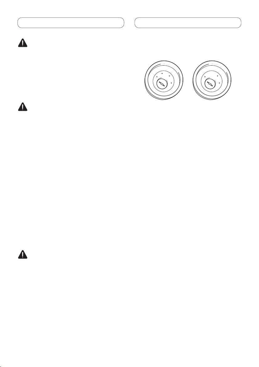
ACC position
No ACC position
• Use this unit in other than the following
conditions could result in fire or malfunction.
— Vehicles with a 12-volt battery and negative
grounding.
— Speakers with 50 W (output value) and 4 ohm
to 8 ohm (impedance value).
• To prevent short-circuit, overheating or
malfunction, be sure to follow the directions
below.
— Disconnect
the negative terminal of the
battery before installation.
— Secure the wiring with cable clamps or
adhesive tape. To protect the wiring, wrap
adhesive tape around them where they lie
against metal parts.
— Place all cables away from moving parts, such
as gear shift and seat rails.
— Place all cables away from hot places, such as
near the heater outlet.
— Do not pass the yellow cable through a hole
into the engine compartment to connect to a
battery.
— Cover
any disconnected cable connectors with
insulating tape.
— Do not shorten any cables.
— Never cut the insulation of the power cable of
this unit in order to share the power to other
equipment. Current capacity of the cable is
limited.
— Use
a fuse of the rating prescribed.
— Never wire the speaker negative cable directly
to ground.
— Never band together multiple speaker’s
negative cables.
• Control signal is output through blue/white cable
when this unit is powered on. Connect it to an
external power amp’s system remote control or
the vehicle’s auto-antenna relay control terminal
(max. 300 mA, 12 V DC). If the vehicle is equipped
with a glass antenna, connect it to the antenna
booster power supply terminal.

Connecting the units
English
• Never connect blue/white cable to external power
amp’s power terminal. Also, never connect
it to the power terminal of the auto antenna.
Otherwise, battery drain or malfunction may
result.
• Black
cable is ground. This cable and other
product’s ground cable (especially, high-current
products such as power amp) must be wired
separately. Otherwise, fire or malfunction may
result if they are accidentally detached.
3
<YRD5342-A> <3>
Connecting the units
Connecting the power cord
4
<YRD5342-A> <4>
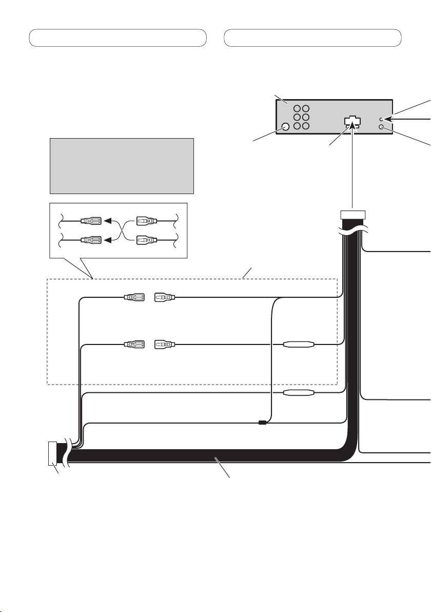
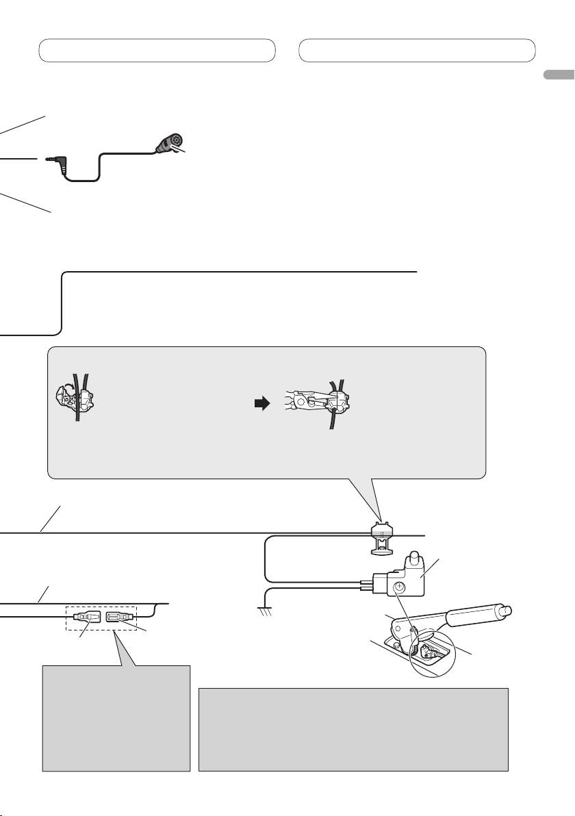
Microphone input
This product
(MVH-8300BT only)
4 m
Microphone
(MVH-8300BT only)
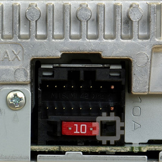
Note:
Antenna input
Fuse (10 A)
Depending on the kind of vehicle, the
Wired remote input
function of 2* and 4* may be different. In
Hard-wired remote control
this case, be sure to connect 1* to 4* and
adaptor can be connected (sold
3* to 2*.
separately).
2*
1*
Yellow/black
If you use equipment with Mute function, wire this lead to the
Audio Mute lead on that piece of equipment. If not, keep the
Audio Mute lead free of any connections.
4*
3*
Connect leads of the same
color to each other.
Connection method
1. Clamp the lead.
2. Clamp firmly with
needle-nosed pliers.
Yellow (2*)
Yellow (1*)
Back-up
Connect to the constant 12 V
(or accessory)
supply terminal.
Note:
· The position of the parking brake switch depends on the vehicle model. For details,
consult the vehicle Owner’s Manual or dealer.
Fuse resistor
Red (4*)
Red (3*)
Accessory
Connect to terminal controlled by
Light green
(or back-up)
ignition switch (12 V DC).
Used to detect the ON/OFF status of the parking brake. This lead
must be connected to the power supply side of the parking brake
switch.
Orange/white
Fuse resistor
Connect to lighting switch terminal.
Blue/white
Parking brake
Connect to system control terminal of the power
Power supply side
switch
Black (chassis ground)
amp (max. 300 mA 12 V DC).
Connect to a clean, paint-free metal location.
Ground side
Blue/white (6*)
ISO connector
Speaker leads
Blue/white (5*)
Connect to auto-antenna relay control terminal
Note:
White: Front left
(max. 300 mA 12 V DC).
In some vehicles, the ISO connector may be
White/black: Front left
divided into two. In this case, be sure to connect
Gray: Front right
The pin position of the ISO
to both connectors.
Gray/black: Front right
connector will differ depending
Notes:
Green: Rear left or subwoofer
on the type of vehicle. Connect
· Change the initial setting of this unit (refer to the Operation Manual).
Green/black: Rear left or subwoofer
5* and 6* when Pin 5 is an
The subwoofer output of this unit is monaural.
Violet: Rear right or subwoofer
antenna control type. In other
· When using a subwoofer of 70 W (2 Ω), be sure to connect with
Violet/black: Rear right or subwoofer
types of vehicles, never connect
Violet and Violet/black leads of this unit. Do not connect anything to
5* and 6*.
Green and Green/black leads.
English
Connecting the power cord
5
<YRD5342-A> <5>
Microphone input
This product
(MVH-8300BT only)
4 m
Microphone
(MVH-8300BT only)
Note:
Antenna input
Fuse (10 A)
Depending on the kind of vehicle, the
Wired remote input
function of 2* and 4* may be different. In
Hard-wired remote control
this case, be sure to connect 1* to 4* and
adaptor can be connected (sold
3* to 2*.
separately).
1*
2*
Yellow/black
If you use equipment with Mute function, wire this lead to the
Audio Mute lead on that piece of equipment. If not, keep the
Audio Mute lead free of any connections.
3*
4*
Connect leads of the same
color to each other.
Connection method
1. Clamp the lead.
2. Clamp firmly with
needle-nosed pliers.
Yellow (2*)
Yellow (1*)
Back-up
Connect to the constant 12 V
(or accessory)
supply terminal.
Note:
· The position of the parking brake switch depends on the vehicle model. For details,
consult the vehicle Owner’s Manual or dealer.
Fuse resistor
Red (4*)
Red (3*)
Accessory
Connect to terminal controlled by
Light green
(or back-up)
ignition switch (12 V DC).
Used to detect the ON/OFF status of the parking brake. This lead
must be connected to the power supply side of the parking brake
switch.
Orange/white
Fuse resistor
Connect to lighting switch terminal.
Blue/white
Parking brake
Connect to system control terminal of the power
Power supply side
switch
Black (chassis ground)
amp (max. 300 mA 12 V DC).
Connect to a clean, paint-free metal location.
Ground side
Blue/white (6*)
Speaker leads
ISO connector
Blue/white (5*)
Connect to auto-antenna relay control terminal
White: Front left
Note:
(max. 300 mA 12 V DC).
White/black: Front left
In some vehicles, the ISO connector may be
Gray: Front right
divided into two. In this case, be sure to connect
The pin position of the ISO
Gray/black: Front right
to both connectors.
connector will differ depending
Notes:
Green: Rear left or subwoofer
on the type of vehicle. Connect
· Change the initial setting of this unit (refer to the Operation Manual).
Green/black: Rear left or subwoofer
5* and 6* when Pin 5 is an
The subwoofer output of this unit is monaural.
Violet: Rear right or subwoofer
antenna control type. In other
· When using a subwoofer of 70 W (2 Ω), be sure to connect with
Violet/black: Rear right or subwoofer
types of vehicles, never connect
Violet and Violet/black leads of this unit. Do not connect anything to
5* and 6*.
Green and Green/black leads.
Connecting the units

Connecting the units
When connecting to separately sold power amp
6
<YRD5342-A> <6>
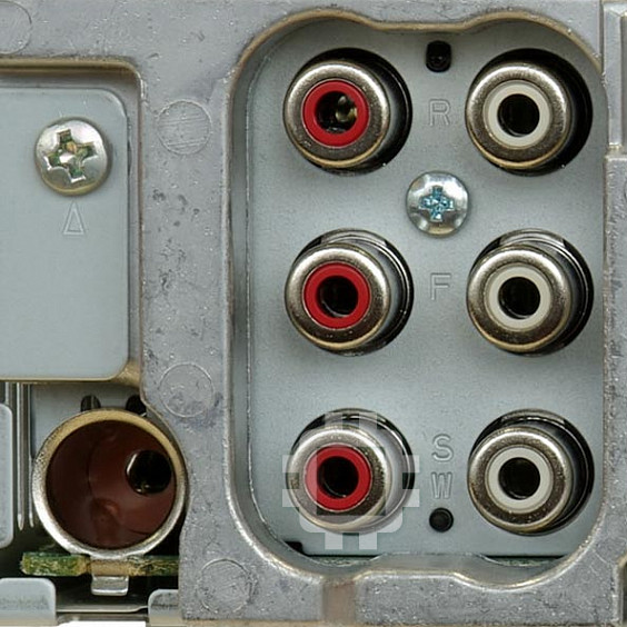
Rear output
Power amp
This product
(sold separately)
To rear output
Power amp
(sold separately)
To front output
Power amp
Front output
(sold separately)
Subwoofer output
To subwoofer
output
Connect with RCA cables
(sold separately)
Blue/white
Connect to system control
terminal of the power amp
(max. 300 mA 12 V DC).
System remote control
Blue/white (6*)
Blue/white (5*)
Connect to auto-antenna
relay control terminal
(max. 300 mA 12 V DC).
The pin position of the ISO connector will
differ depending on the type of vehicle.
Left Right
Connect 5* and 6* when Pin 5 is an
antenna control type. In other types of
vehicles, never connect 5* and 6*.
Subwoofer
Subwoofer
Front speaker Front speaker
Rear speaker
Rear speaker
Perform these connections when
using the optional amplifier.


