Pioneer FH-P80BT: instruction
Class: Auto, Moto equipment and Transportation
Type:

Manual for Pioneer FH-P80BT

English Español Deutsch Français Italiano Nederlands
MANUEL D’INSTALLATION
FH-P80BT
Pycckий
INSTALLATION MANUAL

Contents Connecting the units
Connecting the units ............................ 2
Note
Power cable connection .................................. 4
Connecting to separately sold power amp ...............
6
• When this unit is installed in a vehicle without
ACC (accessory) position on the ignition switch,
red cable must be wired to the terminal that can
Installation ............................................. 8
detect the operation of the ignition key. Otherwise,
battery drain may result.
Before installing this unit ............................... 8
Installation with the holder
and side bracket ........................................ 8
C
A
C
O
O
F
N
F
N
F
F
Installation using the screw holes
O
O
S
S
T
T
on the side of the unit ............................... 9
A
A
R
R
T
T
Installing the microphone ............................. 10
When installing the microphone
on the sun visor .........................................10
ACC position
No ACC position
When installing the microphone
on the steering column ........................... 10
• Use this unit in other than the following
conditions could result in fire or malfunction.
Adjusting the microphone angle .................. 11
— Vehicles with a 12-volt battery and negative
grounding.
— Speakers with 50 W (output value) and 4 ohm
to 8 ohm (impedance value).
• To prevent short-circuit, overheating or
malfunction, be sure to follow the directions
below.
— Disconnect the negative terminal of the
battery before installation.
— Secure the wiring with cable clamps or
adhesive tape. To protect the wiring, wrap
adhesive tape around them where they lie
against metal parts.
— Place all cables away from moving parts, such
as gear shift and seat rails.
— Place all cables away from hot places, such as
near the heater outlet.
— Do not pass the yellow cable through a hole
into the engine compartment to connect to a
battery.
— Cover any disconnected cable connectors with
insulating tape.
— Do not shorten any cables.
— Never cut the insulation of the power cable of
this unit in order to share the power to other
equipment. Current capacity of the cable is
limited.
— Use a fuse of the rating prescribed.
— Never wire the speaker negative cable directly
to ground.
— Never band together multiple speaker’s
negative cables.
2

Connecting the units
English
• Control signal is output through blue/white cable
when this unit is powered on. Connect it to an
external power amp’s system remote control or
the vehicle’s auto-antenna relay control terminal
(max. 300 mA, 12 V DC). If the vehicle is equipped
with a glass antenna, connect it to the antenna
booster power supply terminal.
• Never connect blue/white cable to external power
amp’s power terminal. Also, never connect
it to the power terminal of the auto antenna.
Otherwise, battery drain or malfunction may
result.
• IP-BUS connectors are color-coded. Be sure to
connect connectors of the same color.
• Black cable is ground. This cable and other
product’s ground cable (especially, high-current
products such as power amp) must be wired
separately. Otherwise, fire or malfunction may
result if they are accidentally detached.
3
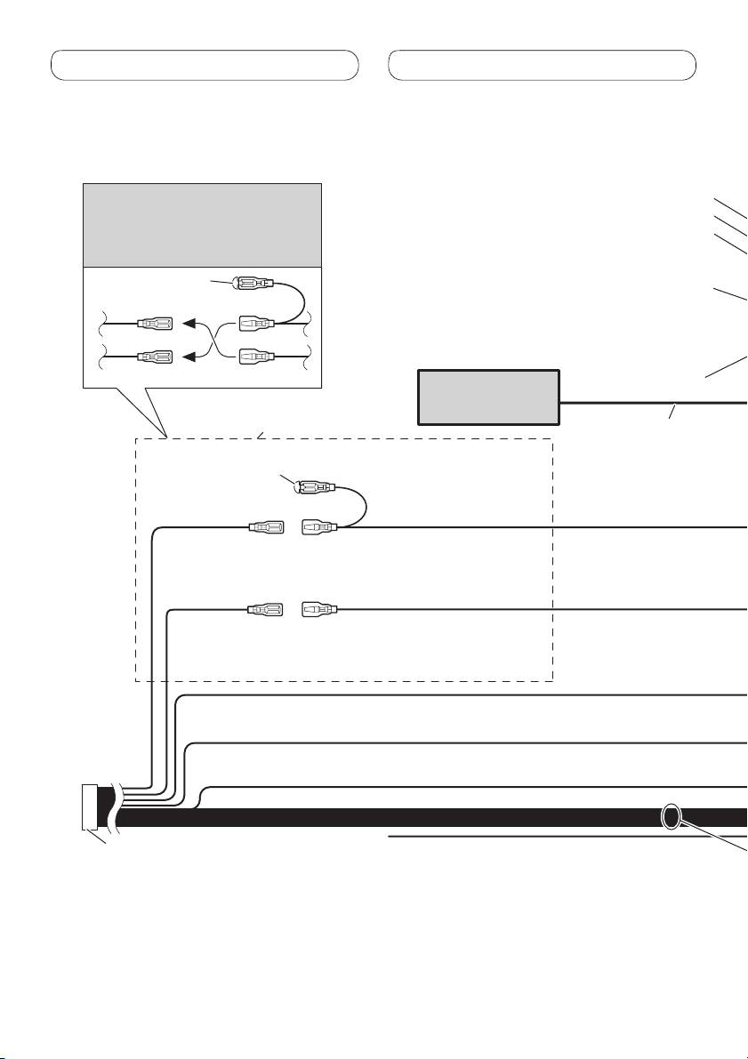
Connecting the units
Power cable connection
Note
Front output
Depending on the kind of vehicle,
Rear output
the function of 3* and 5* may be
Subwoofer output
different. In this case, be sure to
connect 2* to 5* and 4* to 3*.
1*
Antenna jack
3* 2*
4*5*
IP-BUS input (Blue)
Multi-CD player
Connect leads of the same
(sold separately)
color to each other.
IP-BUS cable
Cap (1*)
Do not remove cap if
this terminal is not in
use.
Yellow (3*)
Yellow (2*)
Back-up (or
Connect to the constant
accessory)
12 V supply terminal.
Red (5*)
Red (4*)
Accessory (or
Connect to terminal controlled by
back-up)
ignition switch (12 V DC).
Orange/white
Connect to lighting switch terminal.
Black (chassis ground)
Connect to a clean, paint-free metal location.
ISO connector
Yellow/black
Note
If you use an equipment with Mute
In some vehicles, the ISO connector
function, wire this lead to the Audio
may be divided into two. In this case,
Mute lead on that equipment. If not,
be sure to connect to both connectors.
keep the Audio Mute lead free of any
connections.
4
Table of contents
- Contents Connecting the units
- Connecting the units
- Connecting the units
- Connecting the units
- Installation
- Installation
- Installation
- Installation
- Contenido Conexión de las unidades
- Conexión de las unidades
- Conexión de las unidades
- Conexión de las unidades
- Instalación
- Instalación
- Instalación
- Instalación
- Inhalt Anschließen der Geräte
- Anschließen der Geräte
- Anschließen der Geräte
- Anschließen der Geräte
- Einbauverfahren
- Einbauverfahren
- Einbauverfahren
- Einbauverfahren
- Table des matières Connexions des appareils
- Connexions des appareils
- Connexions des appareils
- Connexions des appareils
- Installation
- Installation
- Installation
- Installation
- Indice Collegamento delle unità
- Collegamento delle unità
- Collegamento delle unità
- Collegamento delle unità
- Installazione
- Installazione
- Installazione
- Installazione
- Inhoud Aansluiten van de toestellen
- Aansluiten van de toestellen
- Aansluiten van de toestellen
- Aansluiten van de toestellen
- Installeren
- Installeren
- Installeren
- Installeren
- Содержание Подключение устройств
- Подключение устройств
- Подключение устройств
- Подключение устройств
- Установка
- Установка
- Установка
- Установка


