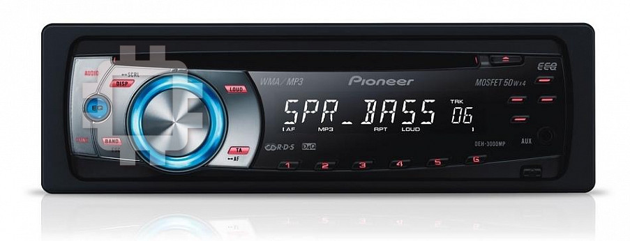
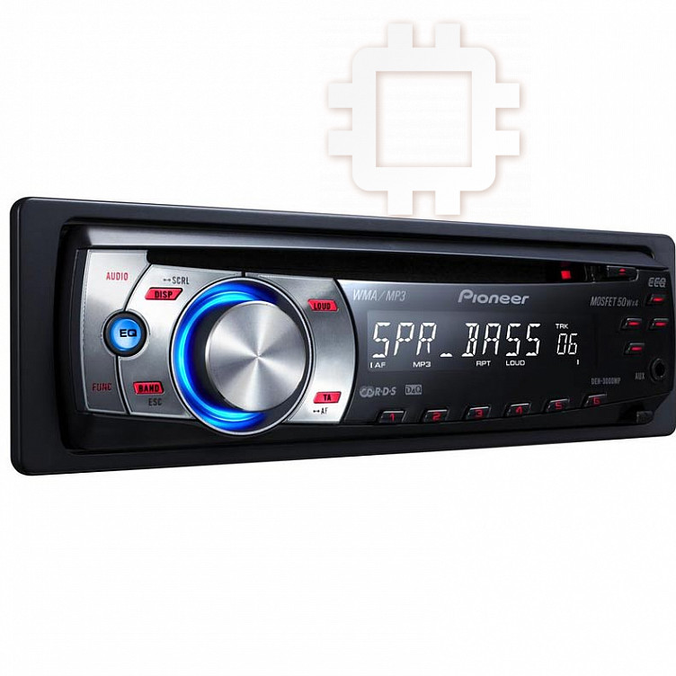
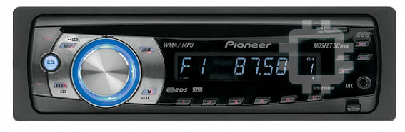
Pioneer DEH-3000MP: instruction
Class: Auto, Moto equipment and Transportation
Type:


Manual for Pioneer DEH-3000MP
MANUEL D’INST
ALLA
TION
INST
ALLA
TION MANUAL
DEH-3000MP
<YRD5137-A/N> 1
<KMMZX> <07H00000>
Printed in Thailand
Imprimé en Thaïlande
<YRD5137-A/N> EW
<YRD5137-A/N> 1
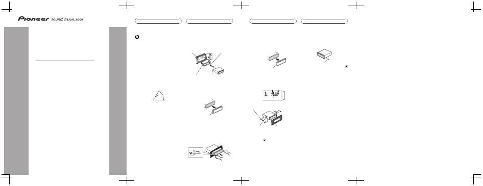
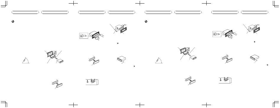
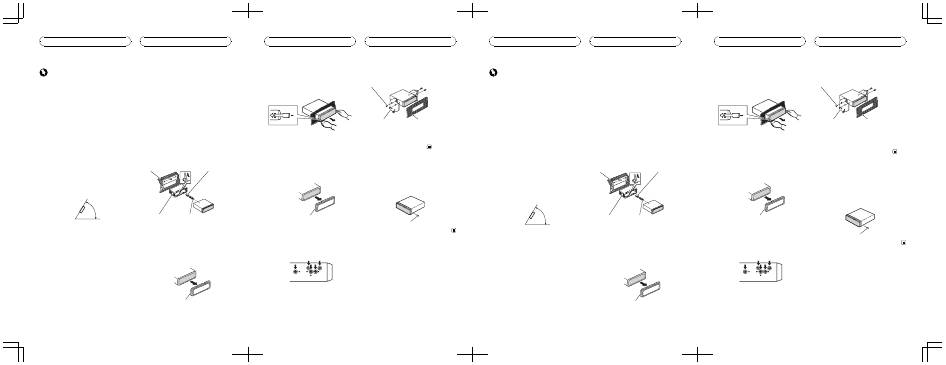
Important
!
Check all connections and systems before
final installation.
!
Do not use unauthorized parts. Use of un-
authorized parts may cause malfunctions.
!
Consult your dealer if installation requires dril-
ling of holes or other modifications to the vehi-
cle.
!
Do not install this unit where :
—
it may interfere with operation of the vehi-
cle.
—
it may cause injury to a passenger as a re-
sult of a sudden stop.
!
The semiconductor laser will be damaged if it
overheats. Install this unit away from hot
places such as near the heater outlet.
!
Optimum performance is obtained when the
unit is installed at an angle of less than 60°.
60°
DIN front/rear mount
This unit can be properly installed either from
“
Front
”
(conventional DIN front-mount) or
“
Rear
”
(DIN rear-mount installation, utilizing
threaded screw holes at the sides of unit chas-
sis). For details, refer to the following installa-
tion methods.
DIN Front-mount
Installation with the rubber bush
1
Insert the mounting sleeve into the
dashboard.
When installing in a shallow space, use a sup-
plied mounting sleeve. If there is enough
space behind the unit, use factory supplied
mounting sleeve.
2
Secure the mounting sleeve by using a
screwdriver to bend the metal tabs (90°)
into place.
3
Install the unit.
Dashboard
Rubber bush
Mounting sleeve
Screw
Removing the unit
1
Extend top and bottom of the trim ring
outwards to remove the trim ring. (When
reattaching the trim ring, point the side
with a groove downwards and attach it.)
Trim ring
!
It becomes easy to remove the trim ring if
the front panel is released.
2
Insert the supplied extraction keys into
both sides of the unit until they click into
place.
3
Pull the unit out of the dashboard.
<YRD5137-A/N>3
Installation
En
<YRD5137-A/N> 2
DIN Rear-mount
1
Extend top and bottom of the trim ring
outwards to remove the trim ring. (When
reattaching the trim ring, point the side
with a groove downwards and attach it.)
Trim ring
!
It becomes easy to remove the trim ring if
the front panel is released.
2
Determine the appropriate position
where the holes on the bracket and the
side of the unit match.
3
Tighten two screws on each side.
Screw
Mounting bracket
Dashboard or console
!
Use either truss screws (5 mm × 8 mm) or
flush surface screws (5 mm × 9 mm), de-
pending on the shape of screw holes in the
bracket.
Fastening the front panel
If you do not plan to detach the front panel,
the front panel can be fastened with supplied
screw.
Screw
<YRD5137-A/N>4
Installation
En
<YRD5137-A/N> 3
<YRD5137-A/N>34
<YRD5137-A/N> 4
Importante
!
Compruebe todas las conexiones y sistemas
antes de la instalación final.
!
No utilice piezas no autorizadas. El uso de pie-
zas no autorizadas puede causar fallos de fun-
cionamiento.
!
Consulte a su concesionario si para la instala-
ción es necesario taladrar orificios o hacer
otras modificaciones al vehículo.
!
No instale esta unidad en un lugar donde:
—
pueda interferir con la conducción del ve-
hículo.
—
pueda lesionar a un pasajero como conse-
cuencia de un frenazo brusco.
!
El láser semiconductor se dañará si se sobre-
calienta. Instale esta unidad alejada de zonas
que alcancen altas temperaturas, como cerca
de la salida del calefactor.
!
Se logra un rendimiento óptimo si la unidad
se instala en un ángulo inferior a 60°.
60°
Montaje delantero/ posterior DIN
Esta unidad se puede instalar adecuadamente ya sea de manera “ delantera ” (montaje delan- tero convencional DIN) o “ posterior ” (instala- ción de montaje posterior DIN, utilizando agujeros roscados para tornillos en los latera- les del bastidor de la unidad). Para obtener de- talles, consulte los siguientes métodos de instalación.
Montaje delantero DIN
Instalación en la arandela de goma 1 Inserte el manguito de montaje en el salpicadero. Si realiza la instalación en un espacio poco profundo, utilice un manguito de montaje su- ministrado. Si hay suficiente espacio detrás de la unidad, utilice un manguito de montaje su- ministrado de fábrica. 2 Fije el manguito de montaje utilizando un destornillador para doblar las pestañas metálicas (90°) y colocarlas en su lugar. 3 Instale la unidad.
Salpicadero
Arandela de goma
Manguito de montaje
Tornillo
Retirada de la unidad 1 Extienda hacia afuera la parte superior e inferior del aro de guarnición para retirar- lo. (Al volver a colocar el anillo de guarni- ción, oriente el lado que tiene una ranura hacia abajo y colóquelo.)
Anillo de guarnición
!
Resulta más fácil retirar el anillo de guarni-
ción si se suelta la carátula.
<YRD5137-A/N>10
Instalación
Es
<YRD5137-A/N> 5
2 Inserte en ambos lados de la unidad las llaves de extracción provistas hasta que se escuche un ligero chasquido. 3 Extraiga la unidad del salpicadero.
Montaje trasero DIN
1 Extienda hacia afuera la parte superior e inferior del aro de guarnición para retirar- lo. (Al volver a colocar el anillo de guarni- ción, oriente el lado que tiene una ranura hacia abajo y colóquelo.)
Anillo de guarnición
!
Resulta más fácil retirar el anillo de guarni-
ción si se suelta la carátula.
2 Determine la posición correcta, de modo que los orificios del soporte y del la- teral de la unidad coincidan. 3 Apriete los dos tornillos en cada lado.
Tornillo
Carcasa
Salpicadero o consola
!
Utilice tornillos de cabeza redonda (5 mm
× 8 mm) o tornillos de cabeza embutida (5
mm × 9 mm), según la forma de los orifi-
cios roscados del soporte.
Fijación de la carátula
Si no tiene previsto sacar la carátula, ésta se puede fijar con el tornillo suministrado.
Tornillo
<YRD5137-A/N>11
Instalación
Es
<YRD5137-A/N> 6
Wichtig
!
Überprüfen Sie vor der definitiven Installation
alle Anschlüsse und Systeme.
!
Verwenden Sie ausschließlich autorisierte
Teile. Die Verwendung nicht autorisierter Teile
kann eine Funktionsstörung zur Folge haben.
!
Wenden Sie sich an Ihren Fachhändler, wenn
für die Installation Löcher gebohrt oder ande-
re Änderungen am Fahrzeug vorgenommen
werden müssen.
!
Installieren Sie dieses Gerät keinesfalls an fol-
genden Orten:
—
Orte, an denen das Gerät die Steuerung
des Fahrzeugs behindern könnte.
—
Orte, an denen das Gerät die Insassen des
Fahrzeugs im Anschluss an eine Schnell-
bremsung verletzen könnte.
!
Der Halbleiterlaser kann durch Überhitzung
beschädigt werden. Installieren Sie dieses
Gerät deshalb in sicherer Entfernung von Hit-
zequellen, wie z. B. Heizöffnungen.
!
Optimale Leistung kann durch eine Installa-
tion des Geräts in einem Winkel unter 60° er-
zielt werden.
60°
Front-/Rückmontage nach DIN
Dieses Gerät kann sowohl über die Frontseite (herkömmliche DIN-Frontmontage) als auch über die Rückseite (DIN-Rückmontage unter Rückgriff auf die Gewindelöcher an den Seiten des Gerätegehäuses) installiert werden. Detail- lierte Informationen können Sie den nachste- henden Beschreibungen dieser Installationsmethoden entnehmen.
DIN-Frontmontage
Installation mit Gummilager 1 Führen Sie den Montagerahmen in das Armaturenbrett ein. Bei nur wenig Installationsraum ist der mitge- lieferte Montagerahmen zu verwenden. Ist hin- ter dem Gerät ausreichend Freiraum vorhanden, dann sollten Sie den werkseitig be- reitgestellten Montagerahmen verwenden. 2 Befestigen Sie den Montagerahmen mithilfe eines Schraubendrehers: Die Me- tallklammern sind in eine sichere Position (90°) zu biegen. 3 Installieren Sie dieses Gerät.
Armaturenbrett
Gummilager
Montagerahmen
Schraube
Entfernen des Geräts 1 Ziehen Sie den Einpassungsring oben und unten nach außen, um ihn zu entfer- nen. (Um den Einpassungsring wieder an- zubringen, drücken Sie die Seite mit der Nute nach unten und befestigen Sie sie.)
Einpassungsring
!
Bei entriegelter Frontplatte lässt sich der
Einpassungsring problemlos entfernen.
<YRD5137-A/N>14
Installation
De
<YRD5137-A/N> 7
2 Führen Sie die mitgelieferten Extrakti- onsschlüssel an beiden Geräteseiten ein, bis sie in der richtigen Position einrasten. 3 Ziehen Sie das Gerät aus dem Armatur- enbrett.
DIN-Rückmontage
1 Ziehen Sie den Einpassungsring oben und unten nach außen, um ihn zu entfer- nen. (Um den Einpassungsring wieder an- zubringen, drücken Sie die Seite mit der Nute nach unten und befestigen Sie sie.)
Einpassungsring
!
Bei entriegelter Frontplatte lässt sich der
Einpassungsring problemlos entfernen.
2 Bestimmen Sie die geeignete Position, damit die Löcher an der Klammer und den Geräteseiten ordnungsgemäß ausgerichtet sind. 3 Ziehen Sie auf jeder Seite zwei Schrau- ben fest.
Schraube
Montageklammer
Armaturenbrett oder Kon-
sole
!
Verwenden Sie entweder Trägerschrauben
(5 mm × 8 mm) oder Oberflächenschrau-
ben (5 mm × 9 mm), je nach der Form der
Gewindelöcher in der Klammer.
Anbringen der Frontplatte
Wenn Sie nicht vorhaben, die Frontplatte abzu- nehmen, kann diese auch mittels der beige- fügten Schrauben permanent angebracht werden.
Schraube
<YRD5137-A/N>15
Installation
De
<YRD5137-A/N> 8
Important
!
Vérifiez toutes les connexions et tous les systè-
mes avant l
’
installation finale.
!
N
’
utilisez pas de pièces détachées non autori-
sées. L
’
utilisation de pièces non autorisées
peut provoquer des dysfonctionnements.
!
Consultez votre revendeur si l
’
installation né-
cessite le perçage de trous ou d
’
autres modifi-
cations du véhicule.
!
N
’
installez pas cet appareil là où :
—
il peut interférer avec l
’
utilisation du véhi-
cule.
—
il peut blesser un passager en cas d
’
arrêt
soudain du véhicule.
!
Le laser à semi-conducteur sera endommagé
s
’
il devient trop chaud. Installez cet appareil à
l
’
écart de tous les endroits chauds, par exem-
ple les sorties de chauffage.
!
Les performances optimales sont obtenues
quand l
’
appareil est installé à un angle infé-
rieur à 60°.
60°
Montage avant/arrière DIN
Cet appareil peut être installé correctement soit à partir de “ l ’ avant ” (montage frontal DIN conventionnel) ou de “ l ’ arrière ” (installation en montage arrière DIN, utilisant des trous de vis filetés sur les côtés du châssis de l ’ appareil). Pour les détails, reportez-vous aux méthodes d ’ installation suivantes.
Montage frontal DIN
Installation avec la douille en caoutchouc 1 Insérez le manchon de montage dans le tableau de bord. Quand vous installez l ’ appareil dans un es- pace peu profond, utilisez un manchon de montage fourni. S ’ il y a assez d ’ espace der- rière l ’ appareil, utilisez le manchon de mon- tage fourni en usine. 2 Fixez le manchon de montage en utili- sant un tournevis pour courber les pattes métalliques (90°) en place. 3 Installez l ’ appareil.
Tableau de bord
Douille en caoutchouc
Manchon de montage
Vis
Enlèvement de l ’ appareil 1 Étirez le haut et le bas de l ’ anneau de garniture vers l ’ extérieur pour retirer la garniture. (Quand vous remontez l ’ anneau de garniture, pointez le côté avec une rai- nure vers le bas et fixez-le.)
Anneau de garniture
!
Il est plus facile de retirer l
’
anneau de garni-
ture si la face avant est libérée.
<YRD5137-A/N>18
Installation
Fr
<YRD5137-A/N> 9
2 Insérez les clés d ’ extraction fournies dans les deux côtés de l ’ appareil jusqu ’ à ce qu ’ elles s ’ enclenchent en place. 3 Tirez l ’ appareil hors du tableau de bord.
Montage arrière DIN
1 Étirez le haut et le bas de l ’ anneau de garniture vers l ’ extérieur pour retirer la garniture. (Quand vous remontez l ’ anneau de garniture, pointez le côté avec une rai- nure vers le bas et fixez-le.)
Anneau de garniture
!
Il est plus facile de retirer l
’
anneau de garni-
ture si la face avant est libérée.
2 Déterminez la position appropriée où les trous sur le support et sur le côté de l ’ appareil se correspondent. 3 Serrez deux vis de chaque côté.
Vis
Support de montage
Tableau de bord ou
console
!
Utilisez des vis à tête bombée (5 mm × 8
mm) ou des vis en affleurement (5 mm × 9
mm), selon la forme des trous de vis dans
le support.
Fixation de la face avant
Si vous ne souhaitez pas détacher la face avant, elle peut être fixée avec les vis fournies.
Vis
<YRD5137-A/N>19
Installation
Fr
<YRD5137-A/N> 10
Importante
!
Controllare tutti i collegamenti e i sistemi
prima dell
’
installazione finale.
!
Non utilizzare componenti non approvati, poi-
ché potrebbero provocare malfunzionamenti.
!
Consultare il rivenditore se l
’
installazione ri-
chiede la trapanatura di fori o altre modifiche
del veicolo.
!
Non installare questa unità se:
—
potrebbe interferire con il funzionamento
del veicolo.
—
potrebbe procurare lesioni al passeggero
in caso di arresto improvviso del veicolo.
!
Se si surriscalda il laser a semiconduttore po-
trebbe subire danni. Non installare questa
unità in luoghi soggetti a surriscaldamento,
come in prossimità delle bocchette dell
’
im-
pianto di riscaldamento.
!
Le prestazioni ottimali si ottengono quando
l
’
unità viene installata con un
’
angolazione in-
feriore a 60°.
60°
Montaggio DIN anteriore/ posteriore
Questa unità può essere installata corretta- mente sia dalla posizione “ Anteriore ” (montag- gio DIN anteriore convenzionale) sia dalla posizione “ Posteriore ” (montaggio DIN poste- riore, per mezzo di fori per le viti ai lati del te- laio) Per dettagli, vedere i seguenti metodi di installazione.
Montaggio DIN anteriore
Installazione con boccola in gomma 1 Inserire la fascetta di montaggio nel cruscotto. Se l ’ unità viene installata in uno spazio poco profondo, utilizzare una fascetta di montaggio fornita. Se dietro l ’ unità vi è spazio sufficiente, utilizzare la fascetta di montaggio fornita. 2 Assicurare la fascetta di montaggio uti- lizzando un cacciavite per piegare le lin- guette metalliche (90°) in posizione. 3 Installazione dell ’ unità.
Cruscotto
Boccola in gomma
Fascetta di montaggio
Vite
Rimozione dell ’ unità 1 Estendere verso l ’ esterno la parte supe- riore e inferiore della guarnizione per ri- muovere la guarnizione. (Quando si riapplica la guarnizione, spingere il lato verso il basso con una guida e applicarla.)
Guarnizione
!
Risulterà facile rimuovere la guarnizione
col frontalino rimosso.
<YRD5137-A/N>22
Installazione
It
<YRD5137-A/N> 11
2 Inserire le chiavi di estrazione fornite su entrambi i lati dell ’ unità fino a che non scattano in posizione. 3 Estrarre l ’ unità dal cruscotto.
Montaggio DIN posteriore
1 Estendere verso l ’ esterno la parte supe- riore e inferiore della guarnizione per ri- muovere la guarnizione. (Quando si riapplica la guarnizione, spingere il lato verso il basso con una guida e applicarla.)
Guarnizione
!
Risulterà facile rimuovere la guarnizione
col frontalino rimosso.
2 Determinare la posizione appropriata, in modo che i fori sulla staffa e sul lato del- l ’ unità corrispondano. 3 Serrare due viti su ciascun lato.
Vite
Staffa di montaggio
Cruscotto o console
!
Utilizzare viti a testa tonda (da 5 mm × 8
mm) o viti a testa piana svasata (da 5 mm
× 9 mm), a seconda della forma dei fori per
le viti sulla staffa.
Rimuovere il frontalino
Se non si intende distaccare il frontalino, que- sto può essere fissato con le viti fornite.
Vite
<YRD5137-A/N>23
Installazione
It
<YRD5137-A/N> 12
Belangrijk
!
Controleer alle aansluitingen en systemen
voordat u de installatie voltooit.
!
Gebruik geen onderdelen van andere fabrikan-
ten. Onderdelen van andere fabrikanten kun-
nen storingen veroorzaken.
!
Neem contact op met uw dealer als er voor de
installatie gaten moeten worden geboord of
als er andere aanpassingen aan het voertuig
nodig zijn.
!
Installeer dit toestel niet op een plaats waar:
—
het de besturing van het voertuig kan be-
lemmeren.
—
het de inzittenden kan verwonden bij een
noodstop.
!
De halfgeleiderlaser raakt bij oververhitting
beschadigd. Plaats dit apparaat niet in de
buurt van plaatsen die warm worden zoals de
afvoer van een kachel.
!
U bent verzekerd van een optimale prestatie
als het toestel wordt geplaatst onder een hoek
van minder dan 60°.
60°
DIN-bevestiging voor/achter
Dit toestel kan zowel langs voren als achteren worden geïnstalleerd. Vóór gebeurt dat via een gewone DIN-montage van voren; achter maakt u gebruik van een DIN-achtermontage en van schroefdraad voorziene gaten aan de zijden van het toestelchassis. Raadpleeg voor meer informatie de volgende installatiemethoden.
DIN-voormontage
Installatie met de rubberen ring 1 Schuif de montagebehuizing in het dashboard. Als u het toestel in een ondiepe ruimte mon- teert, gebruik dan een meegeleverde montage- behuizing. Als er genoeg ruimte achter het toestel is, gebruik dan een van fabriekswege geleverde montagebehuizing. 2 Zet de montagebehuizing vast door met behulp van een schroevendraaier de metalen lipjes (90°) op hun plaats te bui- gen. 3 Installeer het toestel.
Dashboard
Rubberen ring
Montagebehuizing
Schroef
Het toestel verwijderen 1 Trek de boven- en onderkant van de sierlijst naar buiten om deze te verwijde- ren. (Als u de sierlijst weer bevestigt, houdt u de kant met de groef naar onderen en bevestig u hem.)
Sierlijst
!
De sierlijst kan eenvoudig worden verwij-
derd als het voorpaneel is losgemaakt.
<YRD5137-A/N>26
Installatie
Nl
<YRD5137-A/N> 13
2 Steek de meegeleverde uittreksleutels in de beide kanten van het toestel totdat ze op hun plaats klikken. 3 Trek het toestel uit het dashboard.
DIN-achtermontage
1 Trek de boven- en onderkant van de sierlijst naar buiten om deze te verwijde- ren. (Als u de sierlijst weer bevestigt, houdt u de kant met de groef naar onderen en bevestig u hem.)
Sierlijst
!
De sierlijst kan eenvoudig worden verwij-
derd als het voorpaneel is losgemaakt.
2 Bepaal de juiste positie, de plaats waar de gaten op de klem en op de zijde van het toestel gelijk liggen. 3 Draai aan elke kant twee schroeven vast.
Schroef
Bevestigingsklem
Dashboard of console
!
Gebruik schroeven met een platte kop (5
mm × 8 mm) of verzonken schroeven (5
mm × 9 mm), afhankelijk van de vorm van
de schroefgaten in de klem.
Het voorpaneel bevestigen
Als het niet de bedoeling is het voorpaneel los te kunnen maken, kan het met de meegele- verde schroef vast worden bevestigd.
Schroef
<YRD5137-A/N>27
Installatie
Nl
<YRD5137-A/N> 14
Важно
!
Перед окончательной установкой
проверьте все соединения и системы
.
!
Не используйте детали
,
не разрешенные
производителем к использованию
.
Исполь
-
зование таких деталей может стать причи
-
ной возникновения неисправностей в
устройстве
.
!
Узнайте у дилера компании
,
требует ли ус
-
тановка сверления отверстий или
внесения иных изменений в конструкцию
автомобиля
.
!
Не устанавливайте данное устройство в
местах
,
где оно может
:
—
помешать управлению автомобилем
.
—
травмировать пассажира при внезап
-
ной остановке автомобиля
.
!
Перегрев полупроводникового лазера при
-
ведет к его выходу из строя
.
Разместите
все кабели в удалении от нагревающихся
деталей
,
таких как решетка обогревателя
.
!
Оптимальной является установка устрой
-
ства под углом менее
60°.
60°
Переднее / заднее крепление стандарта DIN
Установка данного устройства возможна как спереди ( с помощью обычного перед - него крепления стандарта DIN), так и сзади ( заднее крепление стандарта DIN с ис - пользованием винтов в резьбовых от - верстиях на раме устройства ). Подробности смотрите в прилагаемых ин - струкциях .
Переднее крепление стандарта DIN
Установка с помощью резиновой втулки 1 Вставьте монтажную обойму в переднюю панель . Монтажная обойма применяется в случае установки в недостаточно глубоком гнезде . Заводская монтажная обойма применяется в случае установки устройства при доста - точном пространстве за устройством . 2 Закрепите обойму , подогнув с по - мощью отвертки металлические язычки (90°). 3 Установите устройство .
Приборная панель
Резиновая втулка
Монтажная обойма
Винт
Демонтаж устройства 1 Выдвиньте верхнюю и нижнюю часть декоративной рамки наружу , чтобы снять ее . ( При установке рамки ее сторона с канавкой должна быть внизу .)
Декоративная рамка
!
Рамку легче снимать при снятой
передней панели
.
<YRD5137-A/N>30
Установка
Ru
<YRD5137-A/N> 15
2 Вставьте прилагаемые экстракторы с обеих сторон устройства до щелчка . 3 Вытяните устройство из приборной панели автомобиля .
Заднее крепление стандарта DIN
1 Выдвиньте верхнюю и нижнюю часть декоративной рамки наружу , чтобы снять ее . ( При установке рамки ее сторона с канавкой должна быть внизу .)
Декоративная рамка
!
Рамку легче снимать при снятой
передней панели
.
2 Выберите положения , при котором отверстия на кронштейне и боковых панелях устройства совпадают . 3 Закрутите по два винта с каждой сто - роны .
Винт
Монтажная рамка
Приборная панель или
консоль
!
Используйте винты либо с круглыми
(5
мм
× 8
мм
),
либо с плоскими головками
(5
мм
× 9
мм
),
в зависимости от формы
отверстий под винты кронштейна
.
Закрепление передней панели
Если Вы не собираетесь снимать перед - нюю панель , ее можно закрепить прилагае - мым винтом .
Винт
<YRD5137-A/N>31
Установка
Ru
<YRD5137-A/N> 16
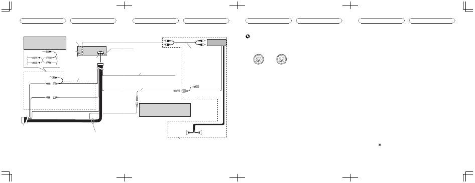
1*
2*
3*
4*
5*
2 Rear
output
1 This
product
3 Antenna
jack
4 Fuse (10 A)
5 Note:
Depending on the kind of vehicle, the function
of 3* and 5* may be different. In this case, be
sure to connect 2* to 5* and 4* to 3*.
6 Connect leads of the same
color to each other.
7 Cap
(1*)
Do not remove cap if this
terminal is not in use.
8 Yellow
(3*)
Back-up
(or accessory)
9 Yellow
(2*)
Connect to the constant 12 V supply
terminal.
10 Red (5*)
Accessory
(or back-up)
11 Red (4*)
Connect to terminal controlled by
ignition switch (12 V DC).
12 Black (chassis ground)
Connect to a clean, paint-free metal location.
13 ISO connector
In some vehicles, the ISO connector may be
divided into two. In this case, be sure to
connect to both connectors.
14 Speaker leads
White: Front left
White/black: Front left
Gray: Front right
Gray/black: Front right
Green: Rear left
Green/black: Rear left
Violet: Rear right
Violet/black: Rear right
<YRD5137-A/N>6
Connections
En
<YRD5137-A/N> 17
Fig. 1
Abb. 1
Afb. 1
Рис. 1
16 Connect with RCA cables
(sold separately)
15 Wired remote input
Hard-wired remote control adaptor can be
connected (sold separately).
19 Blue/white
Connect to system control terminal of the
power amp (max. 300 mA 12 V DC).
18 Yellow/black
If you use an equipment with Mute function,
wire this lead to the Audio Mute lead on that
equipment. If not, keep the Audio Mute lead
free of any connections.
17 Power amp
(sold separately)
20 System remote control
21 Blue/white (7*)
Connect to auto-antenna relay control
terminal (max. 300 mA 12 V DC).
22 Blue/white (6*)
The pin position of the ISO connector will differ depends
on the type of vehicle. Connect 6* and 7* when Pin 5 is
an antenna control type. In another type of vehicle, never
connect 6* and 7*.
23 Left
24 Right
26 Perform these connections when using
the optional amplifier.
25 Rear speaker
25 Rear speaker
<YRD5137-A/N>7
Connections
En
<YRD5137-A/N> 18
Important
!
When this unit is installed in a vehicle without
ACC (accessory) position on the ignition
switch, red cable must be wired to the term-
inal that can detect the operation of the igni-
tion key. Otherwise, battery drain may result.
ACC
ON
S
T
A
R
T
O
FF
ON
S
T
A
R
T
O
FF
ACC position
No ACC position
!
Use of this unit in conditions other than the
following could result in fire or malfunction.
—
Vehicles with a 12-volt battery and negative
grounding.
—
Speakers with 50 W (output value) and 4
ohm to 8 ohm (impedance value).
!
To prevent a short-circuit, overheating or mal-
function, be sure to follow the directions
below.
—
Disconnect the negative terminal of the
battery before installation.
—
Secure the wiring with cable clamps or ad-
hesive tape. To protect the wiring, wrap ad-
hesive tape around them where they lie
against metal parts.
—
Place all cables away from moving parts,
such as gear shift and seat rails.
—
Place all cables away from hot places,
such as near the heater outlet.
—
Do not pass the yellow cable through a
hole into the engine compartment to con-
nect to a battery.
—
Cover any disconnected cable connectors
with insulating tape.
—
Do not shorten any cables.
—
Never cut the insulation of the power cable
of this unit in order to share the power
with other devices. Current capacity of the
cable is limited.
—
Use a fuse of the rating prescribed.
—
Never wire the speaker negative cable di-
rectly to ground.
—
Never band together multiple speaker
’
s ne-
gative cables.
!
Control signal is output through blue/white
cable when this unit is powered on. Connect it
to an external power amp
’
s system remote
control or the vehicle
’
s auto-antenna relay
control terminal (max. 300 mA 12 V DC). If the
vehicle is equipped with a glass antenna, con-
nect it to the antenna booster power supply
terminal.
!
Never connect blue/white cable to external
power amp
’
s power terminal. Also, never con-
nect it to the power terminal of the auto anten-
na. Otherwise, battery drain or malfunction
may result.
!
Black cable is ground. This cable and other
product
’
s ground cable (especially, high-cur-
rent products such as power amp) must be
wired separately. Otherwise, fire or malfunc-
tion may result if they are accidentally de-
tached.
Connection Diagram (Fig. 1)
1
This product
2
Rear output
3
Antenna jack
4
Fuse (10 A)
5
Note:
Depending on the kind of vehicle, the function
of 3* and 5* may be different. In this case, be
sure to connect 2* to 5* and 4* to 3*.
6
Connect leads of the same color to each
other.
7
Cap (1*)
Do not remove cap if this terminal is not in
use.
8
Yellow (3*)
Back-up (or accessory)
9
Yellow (2*)
Connect to the constant 12 V supply terminal.
10 Red (5*)
Accessory (or back-up)
11 Red (4*)
Connect to terminal controlled by ignition
switch (12 V DC).
12 Black (chassis ground)
Connect to a clean, paint-free metal location.
<YRD5137-A/N>8
Connections
En
<YRD5137-A/N> 19
13 ISO connector
In some vehicles, the ISO connector may be
divided into two. In this case, be sure to con-
nect to both connectors.
14 Speaker leads
White: Front left
+
White/black: Front left
*
Gray: Front right
+
Gray/black: Front right
*
Green: Rear left
+
Green/black: Rear left
*
Violet: Rear right
+
Violet/black: Rear right
*
15 Wired remote input
Hard-wired remote control adaptor can be
connected (sold separately).
16 Connect with RCA cables (sold separately)
17 Power amp (sold separately)
18 Yellow/black
If you use an equipment with Mute function,
wire this lead to the Audio Mute lead on that
equipment. If not, keep the Audio Mute lead
free of any connections.
19 Blue/white
Connect to system control terminal of the
power amp (max. 300 mA 12 V DC).
20 System remote control
21 Blue/white (7*)
Connect to auto-antenna relay control term-
inal (max. 300 mA 12 V DC).
22 Blue/white (6*)
The pin position of the ISO connector will dif-
fer depends on the type of vehicle. Connect 6*
and 7* when Pin 5 is an antenna control type.
In another type of vehicle, never connect 6*
and 7*.
23 Left
24 Right
25 Rear speaker
26 Perform these connections when using the
optional amplifier.
<YRD5137-A/N>9
Connections
En
<YRD5137-A/N> 20
Importante
!
Cuando esta unidad se instala en un vehículo
sin posición ACC (accesorio) en la llave de en-
cendido, el cable rojo se debe conectar al ter-
minal que pueda detectar la operación de la
llave de encendido. De lo contrario, puede
descargarse la batería.
ACC
ON
S
T
A
R
T
O
FF
ON
S
T
A
R
T
O
FF
Posición ACC
Sin posición ACC
!
El uso de esta unidad en unas condiciones
distintas de las indicadas a continuación po-
dría causar incendios o fallos de funciona-
miento.
—
Vehículos con una batería de 12 voltios y
conexión a tierra negativa.
—
Altavoces con 50 W (valor de salida) y 4 oh-
mios a 8 ohmios (valor de impedancia).
!
Para evitar cortocircuitos, sobrecalentamiento
o fallos de funcionamiento, asegúrese de se-
guir las siguientes instrucciones.
—
Desconecte el terminal negativo de la bate-
ría antes de la instalación.
—
Asegure el cableado con pinzas para ca-
bles o cinta adhesiva. Para proteger el ca-
bleado, envuelva con cinta adhesiva las
partes en donde esté en contacto con pie-
zas metálicas.
—
Coloque todos los cables alejados de las
partes móviles, como la palanca de cam-
bios y los rieles de los asientos.
—
Coloque todos los cables alejados de luga-
res calientes, como cerca de la salida del
calefactor.
—
No pase el cable amarillo a través de un
orificio en el compartimiento del motor
para conectarlo a la batería.
—
Cubra con cinta aislante los conectores de
cables que queden desconectados.
—
No acorte ningún cable.
—
Nunca corte el aislamiento del cable de ali-
mentación de esta unidad para compartir
la corriente con otros equipos. La capaci-
dad de corriente del cable es limitada.
—
Utilice un fusible con la tensión nominal
indicada.
—
Nunca conecte el cable negativo de los al-
tavoces directamente a tierra.
—
Nunca empalme los cables negativos de
varios altavoces.
!
Cuando se enciende esta unidad, se emite
una señal de control a través del cable azul/
blanco. Conecte la unidad a un mando a dis-
tancia del amplificador de potencia externo o
al terminal de control del relé de la antena
automática del vehículo (máx. 300 mA 12 V
CC). Si el vehículo posee una antena integra-
da en el cristal del parabrisas, conecte la uni-
dad al terminal de la fuente de alimentación
del amplificador de la antena.
!
Nunca conecte el cable azul/blanco al termi-
nal de potencia del amplificador de potencia
externo. Ni tampoco lo conecte al terminal de
potencia de la antena automática. De lo con-
trario, puede descargarse la batería o produ-
cirse un fallo de funcionamiento.
!
El cable negro es el cable a tierra. Este cable y
el cable a tierra de otros productos (especial-
mente productos de alta tensión, como ampli-
ficadores de potencia) se deben conectar por
separado. De lo contrario, puede producirse
un incendio o un fallo de funcionamiento si
se desconectan por accidente.
Diagrama de conexión (Fig. 1)
1
Este producto
2
Salida trasera
3
Conector de antena
4
Fusible (10 A)
5
Nota:
Según el tipo de vehículo, la función de 3* y
5* puede ser diferente. En este caso, asegúre-
se de conectar 2* a 5* y 4* a 3*.
6
Conecte entre sí los cables del mismo color.
<YRD5137-A/N>12
Conexiones
Es
<YRD5137-A/N> 21
7
Cubierta (1*)
No retire la cubierta si no se utiliza este termi-
nal.
8
Amarillo (3*)
Reserva (o accesorio)
9
Amarillo (2*)
Conectar al terminal de alimentación constan-
te de 12 V.
10 Rojo (5*)
Accesorio (o reserva)
11 Rojo (4*)
Conectar al terminal controlado por la llave de
encendido (12 V CC).
12 Negro (toma de tierra del chasis)
Conectar a una parte metálica limpia, sin pin-
tura.
13 Conector ISO
En algunos vehículos, el conector ISO puede
estar dividido en dos. En este caso, asegúrese
de conectar los dos conectores.
14 Cables de altavoces
Blanco: Delantero izquierdo
+
Blanco/negro: Delantero izquierdo
*
Gris: Delantero derecho
+
Gris/negro: Delantero derecho
*
Verde: Trasero izquierdo
+
Verde/negro: Trasero izquierdo
*
Violeta: Trasero derecho
+
Violeta/negro: Trasero derecho
*
15 Entrada remota por cable
Es posible conectar un adaptador de mando a
distancia por cable (se vende por separado).
16 Conectar con cables RCA (se venden por se-
parado)
17 Amplificador de potencia (se vende por sepa-
rado)
18 Amarillo/negro
Si utiliza un equipo con función de silencia-
miento, conecte este cable con el cable de si-
lenciamiento de audio de ese equipo. En caso
contrario, mantenga el cable de silenciamien-
to de audio sin ninguna conexión.
19 Azul/blanco
Conectar al terminal de control del sistema
del amplificador de potencia (máx. 300 mA 12
V CC).
20 Control remoto del sistema
21 Azul/blanco (7*)
Conectar al terminal de control del relé de la
antena automática (máx. 300 mA 12 V CC).
22 Azul/blanco (6*)
La posición de las patillas del conector ISO
será diferente según el tipo de vehículo. Co-
nectar 6* y 7* cuando la Patilla 5 es del tipo
control de antena. En otro tipo de vehículo, no
se deben conectar nunca 6* y 7*.
23 Izquierda
24 Derecha
25 Altavoz trasero
26 Realice estas conexiones cuando utilice el
amplificador opcional.
<YRD5137-A/N>13
Conexiones
Es
<YRD5137-A/N> 22
Wichtig
!
Wenn dieses Gerät in einem Fahrzeug instal-
liert wird, dessen Zündung nicht mit einer
ACC-Position ausgestattet ist, muss das rote
Kabel mit der Klemme verdrahtet werden, die
für die Erkennung der Zündschlüsselbedie-
nung zuständig ist. Andernfalls kann es zu
einer Entleerung der Fahrzeugbatterie kom-
men.
ACC
ON
S
T
A
R
T
O
FF
ON
S
T
A
R
T
O
FF
Zündung mit Position
ACC
Zündung ohne Position
ACC
!
Der Einsatz dieses Geräts in einer anderen als
der nachstehend angegebenen Betriebsum-
gebung kann einen Brand auslösen oder eine
Funktionsstörung zur Folge haben.
—
Kraftfahrzeuge mit 12-Volt-Batterie und ne-
gativer Erdung.
—
Lautsprecher mit 50 W (Ausgabe) und 4
bis 8 Ohm (Impedanz).
!
Um Kurzschluss, Überhitzung oder Funktions-
störungen zu vermeiden, halten Sie sich stets
an die nachstehend aufgeführten Anweisun-
gen:
—
Trennen Sie die Verbindung zur negativen
Anschlussklemme der Fahrzeugbatterie,
bevor Sie das Gerät installieren.
—
Sichern Sie die Kabelführung mit Kabel-
klammern oder Klebeband. Zum Schutz
der Verkabelung sollten die Kabel an allen
Stellen, an denen sie mit Metallteilen in
Berührung kommen, mit Isolierband um-
wickelt werden.
—
Bringen Sie die Kabel in sicherer Entfer-
nung von beweglichen Fahrzeugkompo-
nenten an, wie z. B. Schalthebel und
Sitzschienen.
—
Bringen Sie die Kabel in größtmöglicher
Entfernung von Stellen an, die sich erhit-
zen, wie z. B. die Heizungsöffnung.
—
Führen Sie das gelbe Kabel nicht durch
ein Loch in den Motorraum, um die Verbin-
dung mit der Fahrzeugbatterie herzustel-
len.
—
Kleben Sie freie Kabelanschlüsse mit Iso-
lierband ab.
—
Kürzen Sie die Kabel nicht.
—
Entfernen Sie niemals die Isolierung des
Stromkabels dieses Geräts, um die Strom-
zufuhr mit einem anderen Gerät zu teilen.
Dadurch wird die Stromversorgungslei-
stung des Kabels beeinträchtigt.
—
Verwenden Sie eine Sicherung, die den
vorgegebenen Leistungsmerkmalen ent-
spricht.
—
Verdrahten Sie das negative Lautsprecher-
kabel niemals direkt mit der Erde.
—
Gruppieren Sie niemals die negativen
Kabel mehrerer Lautsprecher.
!
Das Steuersignal wird bei eingeschaltetem
Gerät über das blau/weiße Kabel ausgegeben.
Verbinden Sie dieses Kabel mit der System-
fernbedienung eines externen Leistungsver-
stärkers oder der Steuerklemme des
Automatikantennenrelais des Kraftfahrzeugs
(max. 300 mA, 12 V Gleichspannung). Wenn
das Fahrzeug mit einer in die Heckscheibe in-
tegrierten Radioantenne ausgestattet ist, ver-
binden Sie das Kabel mit der
Versorgungsklemme des Antennenboosters.
!
Verbinden Sie das blau/weiße Kabel niemals
mit der Leistungsklemme des externen Lei-
stungsverstärkers. Darüber hinaus darf das
Kabel keinesfalls mit der Leistungsklemme
der Fahrzeugantenne verbunden werden. An-
dernfalls kann es zu einer Entleerung oder
Funktionsstörung der Fahrzeugbatterie kom-
men.
<YRD5137-A/N>16
Anschlüsse
De
<YRD5137-A/N> 23
!
Das schwarze Kabel gewährleistet die Erdung.
Dieses Kabel wie auch die Erdungskabel an-
derer Produkte (insbesondere von Hochstrom-
produkten wie Leistungsverstärker) müssen
separat verdrahtet werden. Andernfalls kann
es zu einem Brand oder einer Funktionsstö-
rung kommen, wenn sich die Kabel versehent-
lich lösen.
Anschlussschema (Abb. 1)
1
Dieses Produkt
2
Heckausgang
3
Antennenanschluss
4
Sicherung (10 A)
5
Hinweis:
Je nach Fahrzeugtyp können die Funktionen
3* und 5* variieren. Stellen Sie in diesem Fall
sicher, dass der Anschluss von 2* nach 5*
und 4* nach 3* erfolgt.
6
Verbinden Sie jeweils Anschlüsse derselben
Farbe miteinander.
7
Abdeckung (1*)
Belassen Sie die Abdeckung auf dem An-
schluss, sollte dieser nicht verwendet werden.
8
Gelb (3*)
Reserveversorgung (oder Zubehör)
9
Gelb (2*)
Verbindung mit der Klemme der konstanten
12V-Spannungsversorgung
10 Rot (5*)
Zubehör (oder Reserveversorgung)
11 Rot (4*)
Verbindung mit der Klemme der zündungsge-
steuerten Spannungsversorgung (12 V Gleich-
spannung)
12 Schwarz (Fahrgestell-Erdung)
Verbindung mit einem sauberen, farbfreien
Gehäuseteil aus Metall
13 ISO-Anschluss
Bei manchen Fahrzeugtypen kann der ISO-An-
schluss zweigeteilt sein. Stellen Sie in diesem
Fall sicher, dass zu beiden Anschlüssen Ver-
bindungen hergestellt werden.
14 Lautsprecherkabel
Weiß: Vorn links
+
Weiß/Schwarz: Vorn links
*
Grau: Vorn rechts
+
Grau/Schwarz: Vorn rechts
*
Grün: Hinten links
+
Grün/Schwarz: Hinten links
*
Violett: Hinten rechts
+
Violett/Schwarz: Hinten rechts
*
15 Festverdrahtete Fernbedienung
Es besteht die Möglichkeit, einen (separat er-
hältlichen) festverdrahteten Fernbedienungs-
adapter anzuschließen.
16 Verbindung mit Cinch-Kabeln (separat erhält-
lich)
17 Leistungsverstärker (separat erhältlich)
18 Gelb/Schwarz
Wenn Sie ein Gerät mit Stummschaltfunktion
verwenden, verbinden Sie diesen Draht mit
dem Draht der Audio-Stummschaltung dieses
Geräts. Andernfalls sollte der Draht der Audio-
Stummschaltung (Mute) frei bleiben.
19 Blau/Weiß
Verbindung mit der Systemsteuerungsklem-
me des Leistungsverstärkers (max. 300 mA
12 V Gleichspannung)
20 Systemfernbedienung
21 Blau/Weiß (7*)
Verbindung mit der Steuerungsklemme des
Automatikantennenrelais (max. 300 mA 12 V
Gleichspannung)
22 Blau/Weiß (6*)
Die Pin-Position des ISO-Anschlusses variiert
je nach Fahrzeugtyp. Wird Pin 5 zur Steuerung
der Antenne verwendet, verbinden Sie 6* und
7*. Verbinden Sie in jedem anderen Fahrzeug-
typ niemals 6* und 7*.
23 Nach links
24 Nach rechts
25 Hecklautsprecher
26 Führen Sie diese Verkabelungen beim Ge-
brauch eines optionalen Verstärkers durch.
<YRD5137-A/N>17
Anschlüsse
De
<YRD5137-A/N> 24
Important
!
Quand cet appareil est installé dans un véhi-
cule sans position ACC (accessoire) sur le
contact d
’
allumage, le câble rouge doit être
connecté à la borne qui peut détecter l
’
utilisa-
tion de la clé de contact. Sinon, il peut en ré-
sulter un épuisement de la batterie.
ACC
ON
S
T
A
R
T
O
FF
ON
S
T
A
R
T
O
FF
Avec position ACC
Sans position ACC
!
L
’
utilisation de cet appareil dans des condi-
tions autres que les conditions suivantes
pourrait provoquer un incendie ou un mauvais
fonctionnement.
—
Véhicules avec une batterie 12 volts et une
mise à la masse du négatif.
—
Haut-parleurs avec une puissance de sor-
tie de 50 W et une impédance de 4 ohms à
8 ohms.
!
Pour éviter un court-circuit, une surchauffe ou
un dysfonctionnement, assurez-vous de res-
pecter les instructions suivantes.
—
Déconnectez la borne négative de la batte-
rie avant l
’
installation.
—
Fixez le câblage avec des serre-fils ou de la
bande adhésive. Pour protéger les câbles,
enroulez-les de bande adhésive là où ils
sont en contact avec des parties métalli-
ques.
—
Placez les câbles à l
’
écart de toutes les
parties mobiles, telles que le levier de vi-
tesse et les rails des sièges.
—
Placez les câbles à l
’
écart de tous les en-
droits chauds, par exemple les sorties de
chauffage.
—
Ne faites pas passer le câble jaune à tra-
vers un trou dans le compartiment moteur
pour le connecter à la batterie.
—
Recouvrez tous les connecteurs de câbles
qui ne sont pas connectés avec du ruban
adhésif isolant.
—
Ne raccourcissez pas les câbles.
—
Ne coupez jamais l
’
isolation du câble d
’
ali-
mentation de cet appareil pour partager
l
’
alimentation avec d
’
autres appareils. La
capacité en courant du câble est limitée.
—
Utilisez un fusible correspondant aux ca-
ractéristiques spécifiées.
—
Ne câblez jamais le câble négatif du haut-
parleur directement à la masse.
—
Ne réunissez jamais ensemble les câbles
négatifs de plusieurs haut-parleurs.
!
Le signal de commande est émis sur le câble
bleu/blanc quand cet appareil est sous ten-
sion. Connectez-le à la télécommande du sys-
tème d
’
un amplificateur de puissance externe
ou à la borne de commande du relais de l
’
an-
tenne automatique du véhicule (max. 300 mA
12 V CC). Si le véhicule est équipé d
’
une an-
tenne intégrée à la lunette arrière, connectez-
le à la borne d
’
alimentation de l
’
amplificateur
d
’
antenne.
!
Ne connectez jamais le câble bleu/blanc à la
borne d
’
alimentation électrique de l
’
amplifica-
teur externe. Et ne le connectez jamais à la
borne d
’
alimentation de l
’
antenne automa-
tique. Sinon, il peut en résulter un épuisement
de la batterie ou un mauvais fonctionnement.
!
Le câble noir est la masse. Ce câble et les au-
tres câbles de masse des produits (particuliè-
rement les produits avec des courants élevés
tels que l
’
amplificateur de puissance) doivent
être câblés séparément. Sinon, un incendie
ou un mauvais fonctionnement peuvent se
produire si ces câbles sont déconnectés acci-
dentellement.
Schéma de connexion (Fig. 1)
1
Ce produit
2
Sortie arrière
3
Jack d
’
antenne
4
Fusible (10 A)
5
Remarque :
<YRD5137-A/N>20
Connexions
Fr
<YRD5137-A/N> 25
Selon le type de véhicule, 3* et 5* peuvent
avoir une fonction différente. Dans ce cas, as-
surez-vous de connecter 2* à 5* et 4* à 3*.
6
Connectez les fils de même couleur en-
semble.
7
Cache (1*)
Ne retirez pas le cache si cette borne n
’
est
pas utilisée.
8
Jaune (3*)
Alimentation de secours (ou accessoire)
9
Jaune (2*)
Connectez à la borne d
’
alimentation 12 V per-
manente.
10 Rouge (5*)
Accessoire (ou alimentation de secours)
11 Rouge (4*)
Connectez à la borne contrôlée par le contact
d
’
allumage (12 V CC).
12 Noir (masse du châssis)
Connectez sur un endroit métallique propre,
non recouvert de peinture.
13 Connecteur ISO
Dans certains véhicules, il est possible que le
connecteur ISO soit divisé en deux. Dans ce
cas, assurez-vous de connecter les deux
connecteurs.
14 Fils du haut-parleur
Blanc : Avant gauche
+
Blanc/noir : Avant gauche
*
Gris : Avant droite
+
Gris/noir : Avant droite
*
Vert : Arrière gauche
+
Vert/noir : Arrière gauche
*
Violet : Arrière droite
+
Violet/noir : Arrière droite
*
15 Entrée télécommande câblée
Un adaptateur de télécommande câblée
(vendu séparément) peut être connecté.
16 Connectez avec des câbles RCA (vendus sépa-
rément)
17 Amplificateur de puissance (vendu séparé-
ment)
18 Jaune/noir
Si vous utilisez un équipement avec la fonc-
tion Coupure du son, câblez ce fil au fil Cou-
pure Audio de cet équipement. Sinon, ne
connectez rien au fil Coupure Audio.
19 Bleu/blanc
Connectez à la prise de commande du sys-
tème de l
’
amplificateur de puissance (max.
300 mA 12 V CC).
20 Télécommande du système
21 Bleu/blanc (7*)
Connectez à la borne de commande du relais
de l
’
antenne automatique (max. 300 mA 12 V
CC).
22 Bleu/blanc (6*)
La position des broches du connecteur ISO
est différente selon le type de véhicule.
Connectez 6* et 7* lorsque la broche 5 est de
type commande de l
’
antenne. Dans un type
différent de véhicule, ne connectez jamais 6*
et 7*.
23 Gauche
24 Droite
25 Haut-parleur arrière
26 Réalisez ces connexions lors de l
’
utilisation
d
’
un amplificateur optionnel.
<YRD5137-A/N>21
Connexions
Fr
<YRD5137-A/N> 26
Importante
!
Se si installa questa unità in un veicolo che
non dispone della posizione ACC (accessoria)
per l
’
interruttore della chiave di avviamento, il
cavo rosso deve essere collegato al terminale
che può rilevare il funzionamento della chiave
di avviamento. In caso contrario, la batteria
potrebbe scaricarsi.
ACC
ON
S
T
A
R
T
O
FF
ON
S
T
A
R
T
O
FF
Con posizione ACC
Senza posizione ACC
!
Se questa unità viene utilizzata in condizioni
diverse dalle seguenti, potrebbero verificarsi
incendi o malfunzionamenti.
—
Veicoli dotati di batteria da 12 volt e messa
a terra negativa.
—
Altoparlanti con uscita nominale da 50 W
e impedenza nominale compresa tra 4
ohm e 8 ohm.
!
Per evitare rischi di cortocircuito, surriscalda-
mento o malfunzionamento, accertarsi di se-
guire le indicazioni riportate di seguito.
—
Prima dell
’
installazione, scollegare il mor-
setto negativo della batteria.
—
Assicurare i cavi con morsetti per cavi o
nastro adesivo. Per proteggere i cavi, avvol-
gere nastro adesivo attorno agli stessi nei
punti in cui entrano in contatto con parti
metalliche.
—
Posizionare tutti i cavi in modo che non
possano entrare in contatto con compo-
nenti mobili, come la leva del cambio e i bi-
nari dei sedili.
—
Non posizionare i cavi in luoghi soggetti a
surriscaldamento, come le bocchette del-
l
’
impianto di riscaldamento.
—
Non instradare il cavo giallo attraverso fori
del vano motore per collegare la batteria.
—
Rivestire tutti i connettori scollegati con
del nastro isolante.
—
Non mettere in cortocircuito i cavi.
—
Non condividere mai l
’
alimentazione con
altri dispositivi tagliando l
’
isolante del cavo
di alimentazione dell
’
unità. La capacità di
carico di corrente del cavo è limitata.
—
Utilizzare esclusivamente un fusibile con
la portata prescritta.
—
Non collegare mai direttamente a terra il
cavo negativo dell
’
altoparlante.
—
Non legare mai assieme più cavi negativi
degli altoparlanti.
!
Il segnale di controllo viene trasmesso dal
cavo blu/bianco quando l
’
unità viene accesa.
Collegarlo al telecomando del sistema di am-
plificazione di potenza o al terminale di con-
trollo del relè dell
’
antenna automatica del
veicolo (max. 300 mA 12 V CC). Se il veicolo è
dotato di un
’
antenna a vetro, collegarlo al ter-
minale di alimentazione di potenza dell
’
anten-
na.
!
Non collegare mai il cavo blu/bianco al termi-
nale di alimentazione dell
’
amplificatore di po-
tenza esterno. Inoltre, non collegarlo mai al
terminale di alimentazione dell
’
antenna auto.
In caso contrario, la batteria potrebbe scari-
carsi o potrebbero verificarsi malfunziona-
menti.
!
Il cavo nero è la messa a terra. Questo cavo e
l
’
altro cavo di messa a terra del prodotto (so-
prattutto per i prodotti ad alta tensione, quali
l
’
amplificatore di potenza) devono essere col-
legati separatamente. In caso contrario, se
scollegati accidentalmente, potrebbero provo-
care incendi o malfunzionamenti.
Diagramma di collegamento (Fig. 1)
1
Questo prodotto
2
Uscita posteriore
3
Connettore antenna
4
Fusibile (10 A)
5
Nota:
<YRD5137-A/N>24
Collegamenti
It
<YRD5137-A/N> 27
A seconda del tipo di veicolo, la funzione di 3*
e 5* potrebbe essere diversa. In questo caso,
accertarsi di collegare 2* a 5* e 4* a 3*.
6
Collegare insieme i cavi dello stesso colore.
7
Cappuccio (1*)
Non rimuovere il cappuccio se questo termi-
nale non è utilizzato.
8
Giallo (3*)
Riserva (o accessario)
9
Giallo (2*)
Collegare al terminale di alimentazione co-
stante 12 V.
10 Rosso (5*)
Accessorio (o riserva)
11 Rosso (4*)
Collegare al terminale controllato dall
’
interrut-
tore della chiave di avviamento (12 V CC).
12 Nero (messa a terra del telaio)
Collegare ad una parte metallica pulita e non
verniciata.
13 Connettore ISO
In alcuni veicoli, il connettore ISO potrebbe es-
sere diviso in due. In questo caso, accertarsi
di collegare entrambi i connettori.
14 Cavi altoparlanti
Bianco: Anteriore sinistro
+
Bianco/nero: Anteriore sinistro
*
Grigio: Anteriore destro
+
Grigio/nero: Anteriore destro
*
Verde: Posteriore sinistro
+
Verde/nero: Posteriore sinistro
*
Viola: Posteriore destro
+
Viola/nero: Posteriore destro
*
15 Ingresso remoto cablato
È possibile collegare un adattatore per teleco-
mando cablato (venduto a parte).
16 Collegare con cavi RCA (venduti a parte)
17 Amplificatore di potenza (venduto a parte)
18 Giallo/nero
Se si utilizza un apparecchio dotato di funzio-
ne di silenziamento, collegare questo cavo al
cavo di silenziamento audio di tale apparec-
chio. In caso contrario, non collegare il cavo
di silenziamento audio.
19 Blu/bianco
Collegare al terminale di controllo del sistema
dell
’
amplificatore di potenza (max. 300 mA 12
V CC).
20 Telecomando sistema
21 Blu/bianco (7*)
Collegare al terminale di controllo del relè del-
l
’
antenna automatica (max. 300 mA 12 V CC).
22 Blu/bianco (6*)
La posizione dei pin del connettrore ISO sarà
diversa a seconda del tipo di veicolo. Collega-
re 6* e 7* quando il Pin 5 è del tipo controllo
antenna. In un altro tipo di veicolo, non colle-
gare mai 6* e 7*.
23 Sinistra
24 Destra
25 Altoparlante posteriore
26 Eseguire questi collegamenti quando si usa
l
’
amplificatore opzionale.
<YRD5137-A/N>25
Collegamenti
It
<YRD5137-A/N> 28
Belangrijk
!
Als dit toestel wordt geïnstalleerd in een voer-
tuig met een contactschakelaar zonder ACC-
stand (accessoirestand), moet de rode kabel
worden aangesloten op een aansluiting die de
bediening van de contactschakelaar herkent.
Anders kan de accu leeglopen.
ACC
ON
S
T
A
R
T
O
FF
ON
S
T
A
R
T
O
FF
ACC-stand
Geen ACC-stand
!
Gebruik van dit toestel op een andere manier
dan hieronder wordt beschreven, kan leiden
tot brand of storingen.
—
Voertuigen met een accu van 12 volt en ne-
gatieve aarding.
—
Luidsprekers met 50 W (uitgangswaarde)
en 4 tot 8 ohm (impedantiewaarde).
!
Om kortsluiting, oververhitting of storingen te
voorkomen, moet u onderstaande aanwijzin-
gen opvolgen.
—
Koppel de negatieve aansluiting van de
accu los voordat u het toestel installeert.
—
Gebruik kabelklemmen of plakband om de
bekabeling op een veilige manier aan te
brengen. Gebruik plakband om de kabels
te beschermen op plaatsen waar deze
tegen metalen onderdelen liggen.
—
Plaats de kabels niet in de buurt van be-
weegbare onderdelen, zoals de versnel-
lingspook of de rails van de stoelen.
—
Leg geen kabels op plaatsen die heet kun-
nen worden, zoals dichtbij de kachel.
—
Steek de gele kabel niet door een gat naar
het motorcompartiment om de kabel met
de accu te verbinden.
—
Dek kabelaansluitingen die niet worden ge-
bruikt af met isolatietape.
—
Maak de kabels niet korter.
—
Verwijder nooit de isolatie van de voedings-
kabel van dit toestel om andere apparaten
van stroom te voorzien. De stroomcapaci-
teit van de voedingskabel is beperkt.
—
Gebruik alleen zekeringen die overeenko-
men met het aangegeven vermogen.
—
Verbind de negatieve luidsprekerkabel
nooit rechtstreeks met de aarding.
—
Voeg meerdere negatieve luidsprekerka-
bels nooit samen.
!
Als dit apparaat wordt aangezet, wordt het re-
gelingsignaal doorgegeven via de blauw/witte
kabel. Verbind deze met een afstandsbedie-
ning van een extern versterkersysteem of met
de bedieningsaansluiting van de automati-
sche antenne van de auto (max. 300 mA, 12 V
gelijkstroom). Als het voertuig is uitgerust met
een glasantenne, verbind deze dan met de
voedingsaansluiting van de antenne-booster.
!
Verbind de blauw/witte kabel nooit met de voe-
dingsaansluiting van de externe versterker.
Verbind hem ook nooit met de voedingsaan-
sluiting van de automatische antenne. Anders
kan de accu leeglopen of kan er storing optre-
den.
!
De zwarte kabel is de aarding. Deze kabel en
de aardingskabel van andere producten (met
name van producten die veel stroom verbrui-
ken zoals een versterker) moeten afzonderlijk
worden aangebracht. Anders kan er brand of
storing ontstaan wanneer ze per ongeluk los-
raken.
Aansluitingsschema (Afb. 1)
1
Dit product
2
Achteruitgang
3
Antenneaansluiting
4
Zekering (10 A)
5
Opmerking:
De functie van 3* en 5* kan verschillen; dit is
afhankelijk van het type voertuig. Verbind in
dat geval 2* met 5* en 4* met 3*.
6
Verbind kabels van dezelfde kleur met elkaar.
7
Bedekking (1*)
Verwijder deze kap niet als deze aansluiting
niet wordt gebruikt.
<YRD5137-A/N>28
Verbindingen
Nl
<YRD5137-A/N> 29
8
Geel (3*)
Back-up (of accessoire)
9
Geel (2*)
Aansluiten op de constante 12 V voedingsaan-
sluiting.
10 Rood (5*)
Accessoire (of back-up)
11 Rood (4*)
Aansluiten op een aansluiting die door de
contactschakelaar wordt aangestuurd (12 V
gelijkstroom).
12 Zwart (chassisaarding)
Aansluiten op een schone, ongeverfde meta-
len locatie.
13 ISO-connector
Bij sommige voertuigen is de ISO-connector
in twee verdeeld. Verbind in dat geval beide
connectoren.
14 Luidsprekerkabels
Wit: Voor links
+
Wit/zwart: Voor links
*
Grijs: Voor rechts
+
Grijs/zwart: Voor rechts
*
Groen: Achter rechts
+
Groen/zwart: Achter links
*
Violet: Achter rechts
+
Violet/zwart: Achter rechts
*
15 Ingang bedrade afstandsbediening
Een bedrade afstandsbedieningsadapter kan
aangesloten worden (los verkrijgbaar).
16 Aansluiten op RCA-kabels (apart verkrijgbaar)
17 Versterker (apart verkrijgbaar)
18 Geel/zwart
Als u apparatuur met de functie Dempen ge-
bruikt, verbind deze draad dan met de draad
voor audiodemping op die apparatuur. Zo niet,
houd de draad voor audiodemping dan weg
bij andere verbindingen.
19 Blauw/wit
Aansluiten op systeembedieningsaansluiting
van de versterker (max. 300 mA, 12 V gelijk-
stroom).
20 Afstandsbediening systeem
21 Blauw/wit (7*)
Aansluiten op bedieningsaansluiting van de
gemotoriseerde antenne (max. 300 mA, 12 V
gelijkstroom).
22 Blauw/wit (6*)
De pinpositie van de ISO-connector hangt af
van het type voertuig. Als pin 5 de antenne be-
dient, verbindt u 6* en 7*. In andere typen
voertuigen verbindt u 6* en 7* nooit.
23 Links
24 Rechts
25 Luidsprekers achterin
26 Maak deze verbindingen als de optionele ver-
sterker wordt gebruikt.
<YRD5137-A/N>29
Verbindingen
Nl
<YRD5137-A/N> 30
Важно
!
При установке данного устройства на авто
-
мобиле
,
в котором отсутствует положение
АСС
(
дополнительное оборудование
)
ключа зажигания
,
красный кабель должен
быть подключен к клемме
,
которая опреде
-
ляет рабочее положение ключа зажигания
.
В противном случае может возникнуть
утечка тока аккумуляторной батареи
.
ACC
ON
S
T
A
R
T
O
FF
ON
S
T
A
R
T
O
FF
Положение
ACC
Положение
ACC
от
-
сутствует
!
Эксплуатация данного устройства в усло
-
виях
,
отличных от описанных ниже
,
может
привести к пожару или сбою в работе ус
-
тройства
.
—
Транспортные средства с
12-
вольтовым
аккумулятором и заземлением отри
-
цательного полюса
.
—
Громкоговорители
50
Вт
(
выходная
мощность
)
и от
4
до
8
Ом
(
сопротивле
-
ние
).
!
Во избежание короткого замыкания
,
перегрева или неисправностей обязатель
-
но соблюдайте следующие указания
.
—
Перед установкой отсоедините отри
-
цательную клемму аккумулятора
.
—
Закрепите провода при помощи зажи
-
мов или изоляционной ленты
.
Для за
-
щиты проводки заизолируйте провода в
местах их соприкосновения с метал
-
лическими деталями
.
—
Разместите все кабели в удалении от
подвижных деталей
,
таких как рычаг
переключения передач и направляю
-
щие сидений
.
—
Разместите все кабели в удалении от
нагревающихся деталей
,
таких как
решетка обогревателя
.
—
Не пропускайте желтый кабель через
отверстие в моторный отсек для по
-
дключения к аккумулятору
.
—
Изолируйте концы всех неподсоединен
-
ных кабелей изоляционной лентой
.
—
Не укорачивайте кабели
.
—
Никогда не срезайте изоляцию со
шнура питания данного устройства с
целью подачи питания на другое ус
-
тройство
.
Допустимая нагрузка кабеля
по току ограничена
.
—
Используйте предохранитель указанно
-
го номинала
.
—
Запрещается напрямую заземлять от
-
рицательный вывод громкоговорителя
.
—
Запрещается скреплять отрицательные
кабели громкоговорителей вместе
.
!
При включении питания устройства упра
-
вляющий сигнал подается через сине
-
белый провод
.
Подключите его к клемме
панели управления внешнего усилителя
мощности или клемме реле управления
антенны с электроприводом
(
макс
. 300
мА
12
В постоянного тока
).
Если автомобиль
оборудован встроенной в оконное стекло
антенной
,
подсоедините провод к клемме
питания усилителя антенны
.
!
Запрещается подсоединять сине
-
белый
кабель к клемме питания внешнего уси
-
лителя мощности
.
Также запрещается по
-
дсоединять данный провод к клемме
питания антенны с электроприводом
.
В
противном случае может возникнуть
утечка тока аккумуляторной батареи или
иная неисправность
.
!
Черный кабель является заземляющим
.
Данный кабель и заземляющий кабель
другого устройства
(
особенно устройств
,
предназначенных для эксплуатации при
больших токах
,
таких как усилитель мощ
-
ности
)
должны монтироваться отдельно
.
В
противном случае их случайное от
-
соединение может привести к пожару или
неисправности
.
<YRD5137-A/N>32
Соединения
Ru
<YRD5137-A/N> 31
Схема подключения ( Рис . 1)
1
Данное устройство
2
Выход заднего канала
3
Разъем антенны
4
Плавкий предохранитель
(10 A)
5
Примечание
:
В зависимости от типа автомобиля функ
-
ции
3*
и
5*
могут отличаться
.
В этом
случае следует подключить
2*
к
5*
и
4*
к
3*.
6
Подсоедините провода одинакового цвета
другк другу
.
7
Заглушка
(1*)
Не снимайте заглушку
,
если не планируете
использовать данный разъем
.
8
Желтый
(3*)
Резервный разъем
(
или разъем допол
-
нительного оборудования
)
9
Желтый
(2*)
Подключите к клемме источника постоян
-
ного тока
12
В
.
10
Красный
(5*)
Разъем дополнительного оборудования
(
или резервный разъем
)
11
Красный
(4*)
Подключите к клемме
,
на которую подает
-
ся напряжение
(12
В постоянного тока
)
при
включении зажигания
.
12
Черный
(
заземление на массу
)
Подведите к чистой
,
очищенной от краски
металлической поверхности
.
13
Разъем
ISO
В некоторых автомобилях разъем
ISO
может иметь два вывода
.
В этом случае
необходимо подсоединить оба разъема
.
14
Выводы громкоговорителей
Белый
:
Передний левый
+
Белый
/
черный
:
Передний левый
*
Серый
:
Передний правый
+
Серый
/
черный
:
Передний правый
*
Зеленый
:
Задний левый
+
Зеленый
/
черный
:
Задний левый
*
Фиолетовый
:
Задний правый
+
Фиолетовый
/
черный
:
Задний правый
*
15
Вход проводного пульта дистанционного
управления
Служит для подключения проводного
адаптера пульта дистанционного управле
-
ния
(
приобретается отдельно
).
16
Подключите с помощью кабелей
RCA (
при
-
обретаются отдельно
)
17
Усилитель мощности
(
приобретается
отдельно
)
18
Желтый
/
черный
Если используется оборудование
,
имеющее функцию приглушения звука
,
данный провод необходимо подсоединить
к клемме
Audio Mute
данного устройства
.
В
противном случае необходимо проследить
за тем
,
чтобы данный провод не контакти
-
ровал с любыми другими разъемами
.
19
Синий
/
белый
Подключите к клемме панели управления
усилителя мощности
(
макс
. 300
мА
12
В
постоянного тока
).
20
Пульт дистанционного управления систе
-
мой
21
Синий
/
белый
(7*)
Подключите к клемме реле управления ан
-
тенны с электроприводом
(
макс
. 300
мА
12
В постоянного тока
).
22
Синий
/
белый
(6*)
Расположение штекера разъема
ISO
на
различных автомобилях может отличаться
.
Если штекер
5
предназначен для по
-
дключения антенны
,
подсоедините
6*
к
7*.
На других автомобилях подключать
6*
к
7*
запрещается
.
23
Левый
24
Правый
25
Задний громкоговоритель
26
Используйте данную схему подсоединения
при использовании дополнительного уси
-
лителя мощности
.
<YRD5137-A/N>33
Соединения
Ru
<YRD5137-A/N> 32


