Pioneer DEH-X7500SD: instruction
Class: Auto, Moto equipment and Transportation
Type:


Manual for Pioneer DEH-X7500SD

Installation Manual
Manuel d
’installation
Manuale d
’installazione
Manual de instalación
Installationsanleitung
Installatiehandleiding
Руководство по установке
CD RDS RECEIVER
AUTORADIO CD RDS
SINTOLETTORE CD RDS
REPRODUCTOR DE CD CON RECEPTOR RDS
CD RDS-EMPFÄNGER
CD RDS-ONTVANGER
CD RDS ПРИЕМНИК
DEH-X8500DAB
DEH-X8500BT
DEH-X7500SD
English
Nederlands
Deutsch
Español
Italiano
Français
Ру
сский
Important
! Check all connections and systems before
final installation.
! Do not use unauthorized parts as this may
cause malfunctions.
! Consult your dealer if installation requires
drilling of holes or other modifications to the
vehicle.
! Do not install this unit where:
— it may interfere with operation of the vehicle.
— it may cause injury to a passenger as a result
of a sudden stop.
! The semiconductor laser will be damaged if
it overheats. Install this unit away from hot
places such as near the heater outlet.
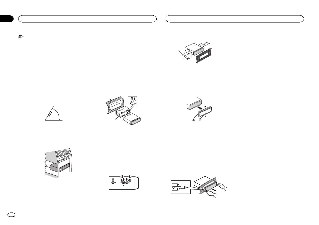
! Optimum performance is obtained when the
unit is installed at an angle of less than 60°.
60°
! When installing, to ensure proper heat dis-
persal when using this unit, make sure you
leave ample space behind the rear panel and
wrap any loose cables so they are not block-
ing the vents.
5cm
cm
Leave ample
space
5 cm
5 cm
DIN front/rear mount
This unit can be properly installed using either
front-mount or rear-mount installation.
Use commercially available parts when instal-
ling.
DIN Front-mount
1
Insert the mounting sleeve into the dash-
board.
For installation in shallow spaces, use the sup-
plied mounting sleeve. If there is enough space,
use the mounting sleeve that came with the ve-
hicle.
2
Secure the mounting sleeve by using a
screwdriver to bend the metal tabs (90°) into
place.
1
2
1 Dashboard
2 Mounting sleeve
# Make sure that the unit is installed securely in
place. An unstable installation may cause skipping
or other malfunctions.
DIN Rear-mount
1
Determine the appropriate position
where the holes on the bracket and the side
of the unit match.
2
Tighten two screws on each side.
1
2
3
1 Tapping screw (5 mm × 8 mm)
2 Mounting bracket
3 Dashboard or console
Removing the unit
1
Remove the trim ring.
1 Trim ring
2 Notched tab
! Releasing the front panel allows easier ac-
cess to the trim ring.
! When reattaching the trim ring, point the
side with the notched tab down.
2
Insert the supplied extraction keys into
both sides of the unit until they click into
place.
3
Pull the unit out of the dashboard.
Removing and re-attaching the front panel
You can remove the front panel to protect your
unit from theft.
Press the detach button and push the front
panel upward and pull it toward you.
For details, refer to operation manual.
Installation
2
Section
Installation
En
01
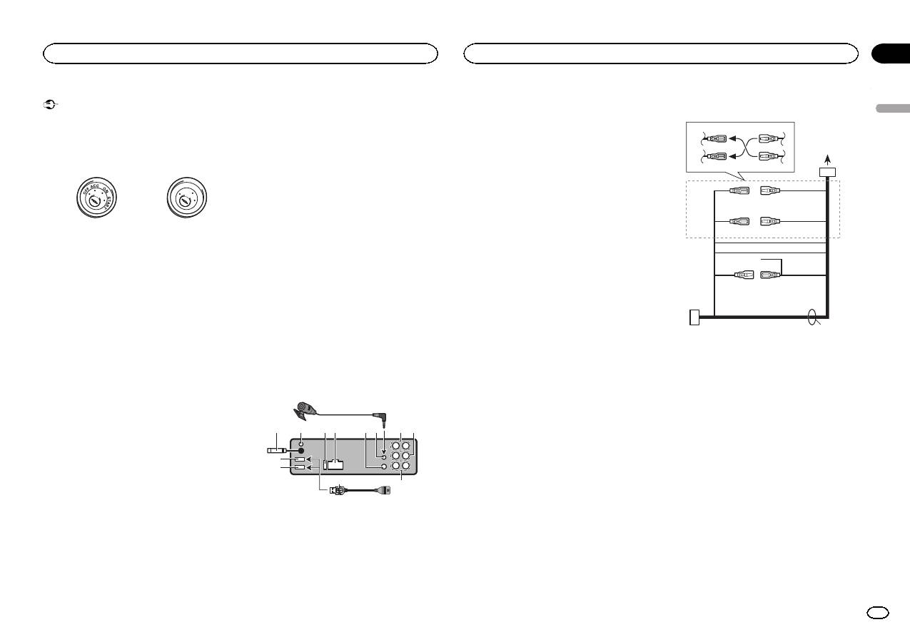
Important
! When installing this unit in a vehicle without
an ACC (accessory) position on the ignition
switch, failure to connect the red cable to the
terminal that detects operation of the ignition
key may result in battery drain.
ON
S
T
A
R
T
O
FF
ACC position
No ACC position
! Use of this unit in conditions other than the
following could result in fire or malfunction.
— Vehicles with a 12-volt battery and negative
grounding.
— Speakers with 50 W (output value) and 4 W to
8
W (impedance value).
! To prevent a short-circuit, overheating or mal-
function, be sure to follow the directions
below.
— Disconnect the negative terminal of the bat-
tery before installation.
— Secure the wiring with cable clamps or adhe-
sive tape. Wrap adhesive tape around wiring
that comes into contact with metal parts to
protect the wiring.
— Place all cables away from moving parts,
such as the shift lever and seat rails.
— Place all cables away from hot places, such
as near the heater outlet.
— Do not connect the yellow cable to the battery
by passing it through the hole to the engine
compartment.
— Cover any disconnected cable connectors
with insulating tape.
— Do not shorten any cables.
— Never cut the insulation of the power cable of
this unit in order to share the power with
other devices. The current capacity of the
cable is limited.
— Use a fuse of the rating prescribed.
— Never wire the negative speaker cable directly
to ground.
— Never band together negative cables of multi-
ple speakers.
! When this unit is on, control signals are sent
through the blue/white cable. Connect this
cable to the system remote control of an ex-
ternal power amp or the vehicle
’s auto-anten-
na relay control terminal (max. 300 mA
12 V DC). If the vehicle is equipped with a
glass antenna, connect it to the antenna
booster power supply terminal.
! Never connect the blue/white cable to the
power terminal of an external power amp.
Also, never connect it to the power terminal
of the auto antenna. Doing so may result in
battery drain or a malfunction.
! The black cable is ground. Ground cables for
this unit and other equipment (especially,
high-current products such as power amps)
must be wired separately. If they are not, an
accidental detachment may result in a fire or
malfunction.
This unit
3
5 6
a
7
b
c
8
1
2
9
d
4
1 USB port 1
2 USB port 2 (DEH-X8500DAB and DEH-
X8500BT only)
3 Antenna input
15 cm
4 DAB antenna input (DEH-X8500DAB only)
To receive DAB signals, connect a DAB an-
tenna (AN-DAB1) sold separately to the unit.
5 Fuse (10 A)
6 Power cord input
7 Wired remote input
Hard-wired remote control adapter can be
connected (sold separately).
8 Microphone input (DEH-X8500DAB and
DEH-X8500BT only)
9 Microphone (DEH-X8500DAB and DEH-
X8500BT only)
4 m
a Rear output
b Front output
c Subwoofer output
d USB cable
1.5 m
! Only for DEH-X8500DAB and DEH-X8500BT
If connecting both
USB1 (USB storage
device1)/
iPod1 (iPod connected using
USB input1) and
USB2 (USB storage de-
vice2)/
iPod2 (iPod connected using USB
input2) at the same time, use a Pioneer
USB cable (CD-U50E) in addition to the
regular Pioneer USB cable.
Power cord
1
3
3
2
4
4
5
5
6
6
b
8
9
a
7
c
e
d
1 To power cord input
2 Depending on the kind of vehicle, the func-
tion of
3 and 5 may be different. In this
case, be sure to connect
4 to 5 and 6 to
3.
3 Yellow
Back-up (or accessory)
4 Yellow
Connect to the constant 12 V supply termi-
nal.
5 Red
Accessory (or back-up)
6 Red
Connect to terminal controlled by ignition
switch (12 V DC).
7 Connect leads of the same color to each
other.
8 Orange/white
Connect to lighting switch terminal.
9 Black (chassis ground)
English
Connections
3
Section
Connections
En
02
Table of contents
- DIN front/rear mount
- This unit
- Power amp (sold separately)
- Adjusting the microphoneangle
- Montage avant/arrière DIN
- Cet appareil
- Amplificateur de puissance(vendu séparément)
- Si vous installez lemicrophone sur le pare-soleil
- Montaggio DIN anteriore/posteriore
- Questa unità
- Amplificatore di potenza(venduto a parte)
- Installazione del microfonosull ’aletta parasole
- Montaje delantero/posteriorde DIN
- Esta unidad
- Amplificador de potencia(se vende por separado)
- Instalación del micrófono enel parasol
- Front-/Rückmontage nach DIN
- Dieses Gerät
- Leistungsverstärker (separaterhältlich)
- Befestigen des Mikrofons ander Sonnenblende
- DIN-bevestiging voor/achter
- Dit toestel
- Versterker (apart verkrijgbaar)
- De hoek van de microfoonafstellen
- Переднее/заднеекрепление стандарта DIN
- Данное устройство
- Усилитель мощности(приобретается отдельно)
- При установке микрофона насолнцезащитном козырьке


