Pioneer DEH-P65BT: instruction
Class: Auto, Moto equipment and Transportation
Type:


Manual for Pioneer DEH-P65BT
English
MANUEL D’INSTALLATION
Español
Deutsch
DEH-P65BT
Français
Italiano
This product conforms to new cord colors.
Los colores de los cables de este producto se confor-
man con un nuevo código de colores.
Dieses Produkt entspricht den neuen Kabelfarben.
Nederlands
Le code de couleur des câbles utilisé pour ce produit est
nouveau.
Questo prodotto è conforme ai nuovi codici colori.
De kleuren van de snoeren van dit toestel zijn gewijzigd.
чÌÌÓ ÛÒÚÓÈÒÚ‚Ó ÒÓÓÚ‚ÂÚÒÚ‚ÛÂÚ ÌÓ‚˚Ï
Ú·ӂ‡ÌËflÏ Í ˆ‚ÂÚÛ ÔÓ‚Ó‰Ó‚.
PyÒÒÍËÈ
INSTALLATION MANUAL

Contents
Connecting the Units
Connecting the Units ................................ 1
Note:
Power cable connection .................................... 3
• When this unit is installed in a vehicle without
ACC (accessory) position on the ignition switch,
Connecting to separately sold power amp ........ 5
red cable must be wired to the terminal that can
detect the operation of the ignition key.
Installation .................................................. 7
Otherwise, battery drain may result.
DIN Front/Rear-mount ...................................... 7
DIN Front-mount .............................................. 7
DIN Rear-mount ................................................ 8
Fastening the front panel .................................. 9
Installing the microphone .................................. 9
Adjusting the microphone angle ......................10
No ACC positionACC position
• Use this unit in other than the following condi-
tions could result in fire or malfunction.
— Vehicles with a 12-volt battery and negative
grounding.
— Speakers with 50 W (output value) and 4 ohm
to 8 ohm (impedance value).
• To prevent short-circuit, overheating or malfunc-
tion, be sure to follow the directions below.
— Disconnect the negative terminal of the bat-
tery before installation.
— Secure the wiring with cable clamps or adhe-
sive tape. To protect the wiring, wrap adhe-
sive tape around them where they lie against
metal parts.
— Place all cables away from moving parts,
such as gear shift and seat rails.
— Place all cables away from hot places, such as
near the heater outlet.
— Do not pass the yellow cable through a hole
into the engine compartment to connect to a
battery.
— Cover any disconnected cable connectors
with insulating tape.
— Do not shorten any cables.
— Never cut the insulation of the power cable of
this unit in order to share the power to other
equipment. Current capacity of the cable is
limited.
— Use a fuse of the rating prescribed.
— Never wire the speaker negative cable direct-
ly to ground.
— Never band together multiple speaker’s nega-
tive cables.
1
A
C
C
O
O
F
N
F
N
F
F
O
O
S
S
T
T
A
A
R
R
T
T

• Control signal is output through blue/white cable
English
when this unit is powered on. Connect it to an
external power amp’s system remote control or
the vehicle’s auto-antenna relay control terminal
(max. 300 mA, 12 V DC). If the vehicle is
equipped with a glass antenna, connect it to the
antenna booster power supply terminal.
• Never connect blue/white cable to external power
amp’s power terminal. Also, never connect it to
Español
the power terminal of the auto antenna.
Otherwise, battery drain or malfunction may
result.
• IP-BUS connectors are color-coded. Be sure to
connect connectors of the same color.
• Black cable is ground. This cable and other prod-
uct’s ground cable (especially, high-current prod-
ucts such as power amp) must be wired separate-
Deutsch
ly. Otherwise, fire or malfunction may result if
they are accidentally detached.
• Cord function may differ according to the
product, even if cord color is the same. When
connecting this system, be sure to check all
manuals and connect cords correctly.
Français
FRANÇAIS
Italiano
Nederlands
2
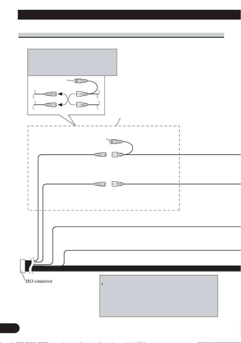
Connecting the Units
3
1*
3*
2*
5*
4*
N
ote
:
Dependin
g
on the kind of vehicle, the function
of 3* and 5* ma
y
be different. In this case, be
sure to connect 2* to
5
* and 4* to
3
*
.
Connect leads of the same
color to each other.
Cap (1*)
Do not remove cap if
this terminal is not in
use.
Yellow (3*)
Yellow (2*)
Back-up (or
Connect to the constant
accessory)
12 V supply terminal.
Red (5*)
Red (4*)
Accessory
Connect to terminal controlled
(or back-up)
by ignition switch (12 V DC).
N
ote
:
In some vehicles
,
the ISO connecto
r
ma
y
be divided into two. In this case,
be sure to connect to both connectors.
N
otes
:
•
Chan
g
e the initial settin
g
of this unit (refer to the
O
p
eration Manual). The subwoofer out
p
ut of this unit is
monaural
.
•
When usin
g
a subwoofer of 70 W (2
Black (chassis ground)
Connect to a clean, paint-free metal location.
Ω) , be sure to
connect with Violet and Violet/black leads of this unit. Do
not connect anything with Green and Green/black leads.
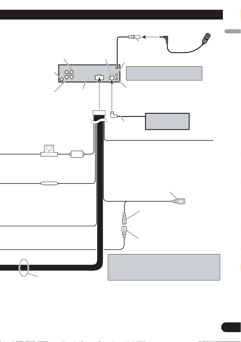
Power cable connection
English
Español
Deutsch
Français
Italiano
Nederlands
4
4 m
Front output
(Refer to page 5 to 6.)
Antenna jack
Rear output or
This product
subwoofer output
(Refer to page 5 to 6.)
Yellow/black
If you use an equipment with Mute function, wire
this lead to the Audio Mute lead on that equipment.
If not, keep the Audio Mute lead free of any
Fuse (10 A)
connections.
Blue/white
Connect to system control terminal of the
power amp (max. 300 mA 12 V DC).
Fuse resistor
Blue/white (7*)
Connect to auto-antenna relay control
terminal (max. 300 mA 12 V DC).
The pin position of the ISO connector will differ depends
on the type of vehicle. Connect 6* and 7* when Pin 5 is
an antenna control type. In another type of vehicle, never
connect 6* and 7*.
Speaker leads
White: Front left +
White/black: Front left ≠
Gray: Front right +
Gray/black: Front right ≠
Green: Rear left + or subwoofer +
Green/black: Rear left ≠ or subwoofer ≠
Violet: Rear right + or subwoofer +
Violet/black: Rear right ≠ or subwoofer ≠
AUX
j
ack (3.5
ø
)
Wired remote in
p
u
t
H
ard-wired remote control ada
p
tor can be
connected (sold separately)
.
IP-BUS input
(Blue)
IP-BUS cable
Multi-CD pla
y
e
r
14 cm
(sold separately)
Blue/white (6*)
Use a stereo mini plu
g
cable to connec
t
with auxiliar
y
equipment
.
Microphone
Microphone input
Table of contents
- Connecting the Units
- Connecting the Units
- Connecting the Units
- Installation
- Installation
- Conexión de las unidades
- Conexión de las unidades
- Conexión de las unidades
- Instalación
- Instalación
- Anschließen der Geräte
- Anschließen der Geräte
- Anschließen der Geräte
- Einbau
- Einbau
- Connexion des appareils
- Connexion des appareils
- Connexion des appareils
- Installation
- Installation
- Collegamento delle unità
- Collegamento delle unità
- Collegamento delle unità
- Installazione
- Installazione
- Aansluiten van de toestellen
- Aansluiten van de toestellen
- Aansluiten van de toestellen
- Installatie
- Installatie
- èÓ‰Íβ˜ÂÌË ÛÒÚÓÈÒÚ‚
- èÓ‰Íβ˜ÂÌË ÛÒÚÓÈÒÚ‚
- èÓ‰Íβ˜ÂÌË ÛÒÚÓÈÒÚ‚
- ìÒÚ‡Ìӂ͇
- ìÒÚ‡Ìӂ͇


