Pioneer DEH-P65BT: Connecting the Units
Connecting the Units: Pioneer DEH-P65BT
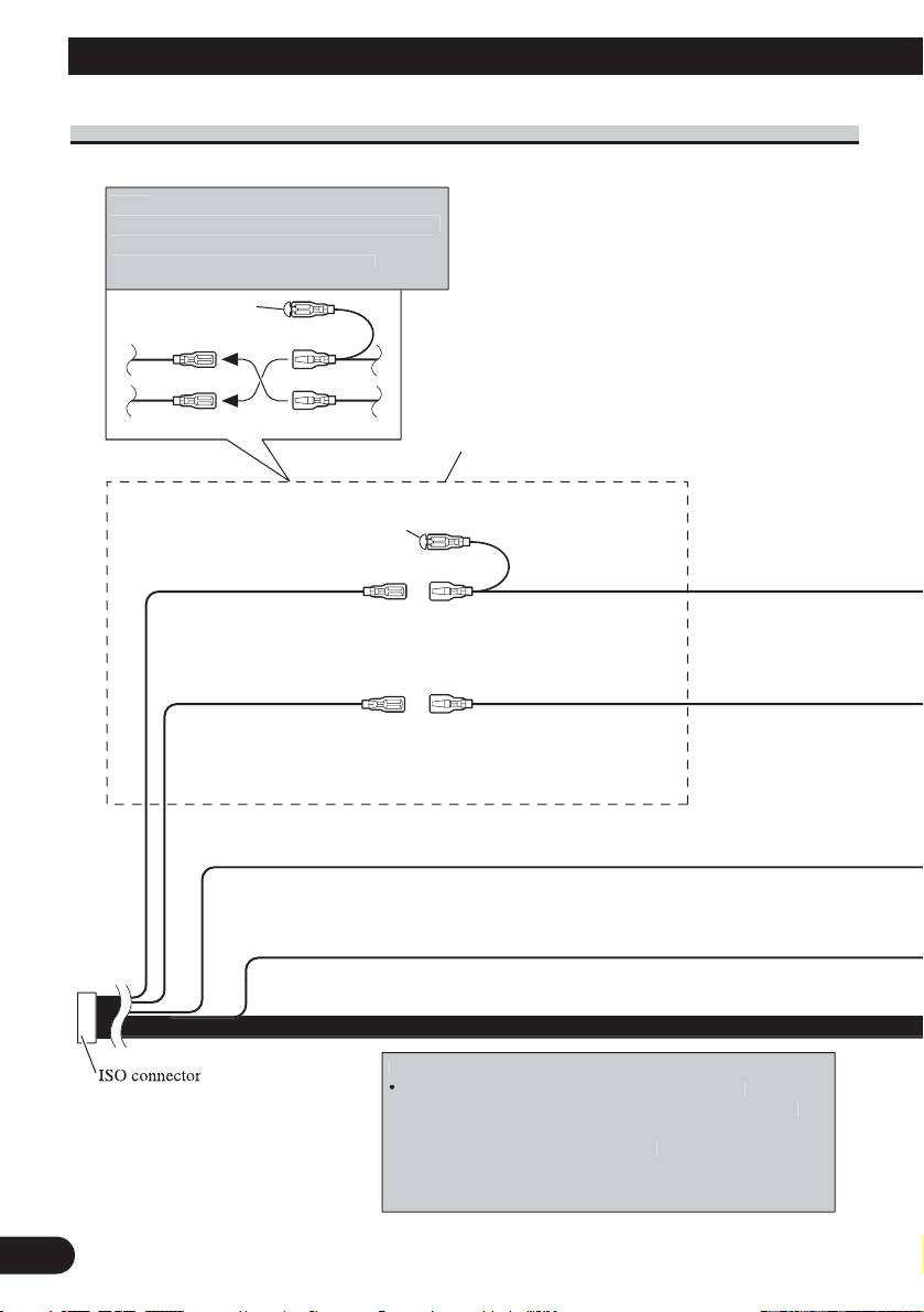
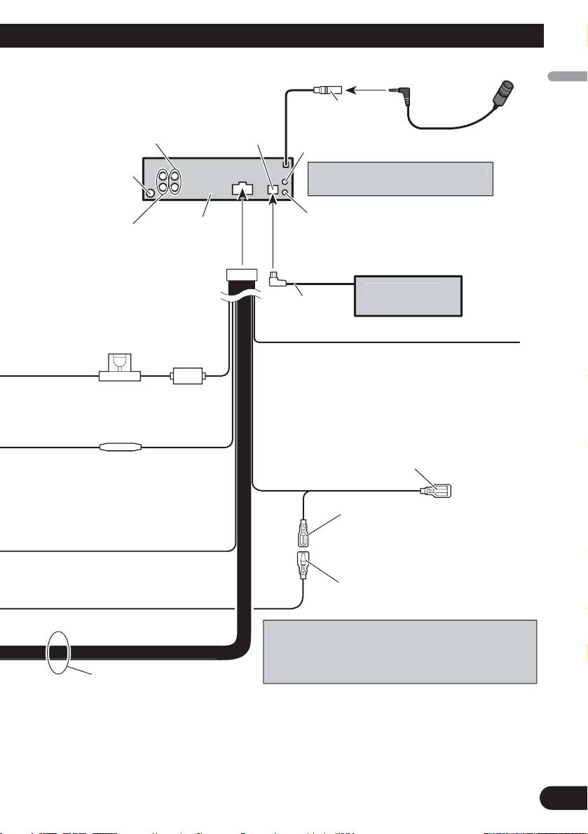
Connecting the Units
3
1*
3*
2*
5*
4*
N
ote
:
Dependin
g
on the kind of vehicle, the function
of 3* and 5* ma
y
be different. In this case, be
sure to connect 2* to
5
* and 4* to
3
*
.
Connect leads of the same
color to each other.
Cap (1*)
Do not remove cap if
this terminal is not in
use.
Yellow (3*)
Yellow (2*)
Back-up (or
Connect to the constant
accessory)
12 V supply terminal.
Red (5*)
Red (4*)
Accessory
Connect to terminal controlled
(or back-up)
by ignition switch (12 V DC).
N
ote
:
In some vehicles
,
the ISO connecto
r
ma
y
be divided into two. In this case,
be sure to connect to both connectors.
N
otes
:
•
Chan
g
e the initial settin
g
of this unit (refer to the
O
p
eration Manual). The subwoofer out
p
ut of this unit is
monaural
.
•
When usin
g
a subwoofer of 70 W (2
Black (chassis ground)
Connect to a clean, paint-free metal location.
Ω) , be sure to
connect with Violet and Violet/black leads of this unit. Do
not connect anything with Green and Green/black leads.
Power cable connection
English
Español
Deutsch
Français
Italiano
Nederlands
4
4 m
Front output
(Refer to page 5 to 6.)
Antenna jack
Rear output or
This product
subwoofer output
(Refer to page 5 to 6.)
Yellow/black
If you use an equipment with Mute function, wire
this lead to the Audio Mute lead on that equipment.
If not, keep the Audio Mute lead free of any
Fuse (10 A)
connections.
Blue/white
Connect to system control terminal of the
power amp (max. 300 mA 12 V DC).
Fuse resistor
Blue/white (7*)
Connect to auto-antenna relay control
terminal (max. 300 mA 12 V DC).
The pin position of the ISO connector will differ depends
on the type of vehicle. Connect 6* and 7* when Pin 5 is
an antenna control type. In another type of vehicle, never
connect 6* and 7*.
Speaker leads
White: Front left +
White/black: Front left ≠
Gray: Front right +
Gray/black: Front right ≠
Green: Rear left + or subwoofer +
Green/black: Rear left ≠ or subwoofer ≠
Violet: Rear right + or subwoofer +
Violet/black: Rear right ≠ or subwoofer ≠
AUX
j
ack (3.5
ø
)
Wired remote in
p
u
t
H
ard-wired remote control ada
p
tor can be
connected (sold separately)
.
IP-BUS input
(Blue)
IP-BUS cable
Multi-CD pla
y
e
r
14 cm
(sold separately)
Blue/white (6*)
Use a stereo mini plu
g
cable to connec
t
with auxiliar
y
equipment
.
Microphone
Microphone input
Table of contents
- Connecting the Units
- Connecting the Units
- Connecting the Units
- Installation
- Installation
- Conexión de las unidades
- Conexión de las unidades
- Conexión de las unidades
- Instalación
- Instalación
- Anschließen der Geräte
- Anschließen der Geräte
- Anschließen der Geräte
- Einbau
- Einbau
- Connexion des appareils
- Connexion des appareils
- Connexion des appareils
- Installation
- Installation
- Collegamento delle unità
- Collegamento delle unità
- Collegamento delle unità
- Installazione
- Installazione
- Aansluiten van de toestellen
- Aansluiten van de toestellen
- Aansluiten van de toestellen
- Installatie
- Installatie
- èÓ‰Íβ˜ÂÌË ÛÒÚÓÈÒÚ‚
- èÓ‰Íβ˜ÂÌË ÛÒÚÓÈÒÚ‚
- èÓ‰Íβ˜ÂÌË ÛÒÚÓÈÒÚ‚
- ìÒÚ‡Ìӂ͇
- ìÒÚ‡Ìӂ͇


