Pioneer DEH-P4900IB: instruction
Class: Auto, Moto equipment and Transportation
Type:
Manual for Pioneer DEH-P4900IB
Note:
•
Check all connections and systems before final
installation.
•
Do not use unauthorized parts. The use of
unauthorized parts may cause malfunctions.
•
Consult with your dealer if installation requires
drilling of holes or other modifications of the
vehicle.
•
Do not install this unit where:
— it may interfere with operation of the vehicle.
— it may cause injury to a passenger as a result
of a sudden stop.
•
The semiconductor laser will be damaged if it
overheats. Install this unit away from hot places
such as near the heater outlet.
•
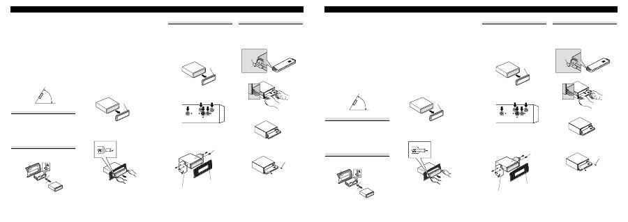
Optimum performance is obtained when the unit
is installed at an angle of less than 60°.
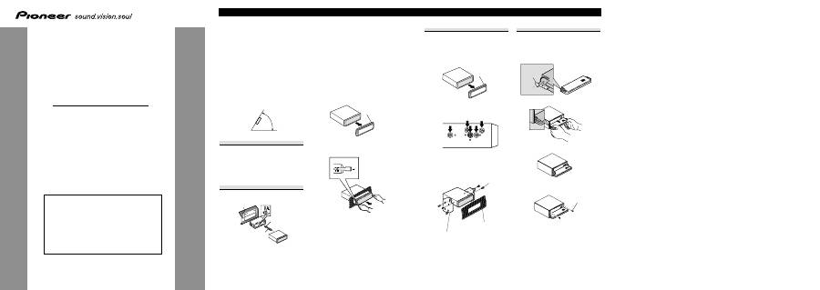
DIN Front/Rear-mount
This unit can be properly installed either from
“Front” (conventional DIN Front-mount) or
“Rear” (DIN Rear-mount installation, utilizing
threaded screw holes at the sides of unit chassis).
For details, refer to the following installation
methods.
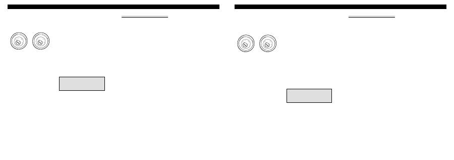
DIN Front-mount
Installation with the rubber bush
1. Insert the mounting sleeve into the dashboard.
•
When installing in a shallow space, use a sup-
plied mounting sleeve. If there is enough
space behind the unit, use factory supplied
mounting sleeve.
2. Secure the mounting sleeve by using a screwdriv-
er to bend the metal tabs (90°) into place.
3. Install the unit as illustrated.
Removing the Unit
1. Extend top and bottom of the trim ring outwards
to remove the trim ring. When reattaching the
trim ring, push the trim ring onto the unit until it
clicks. (If the trim ring is attached upside down,
the trim ring will not fit properly.)
•
It becomes easy to remove the trim ring if the
front panel is released.
2. Insert the supplied extraction keys into both sides
of the unit until they click into place.
3. Pull the unit out of the dashboard.
53
53
1
1
182
182
60
°
Installation
ENGLISH
INST
ALLA
TION MANUAL
MANUEL D’INST
ALLA
TION
<KMINX> <06J00000>
DEH-P4900IB
Printed in Thailand
Imprimé en Thaïlande
<XRD7126-A/N> EW
This product conforms to new cord colors.
Los colores de los cables de este producto se confor-
man con un nuevo código de colores.
Dieses Produkt entspricht den neuen Kabelfarben.
Le code de couleur des câbles utilisé pour ce produit
est nouveau.
Questo prodotto è conforme ai nuovi codici colori.
De kleuren van de snoeren van dit toestel zijn gewijzigd.
чÌÌÓ ÛÒÚÓÈÒÚ‚Ó ÒÓÓÚ‚ÂÚÒÚ‚ÛÂÚ ÌÓ‚˚Ï
Ú·ӂ‡ÌËflÏ Í ˆ‚ÂÚÛ ÔÓ‚Ó‰Ó‚.
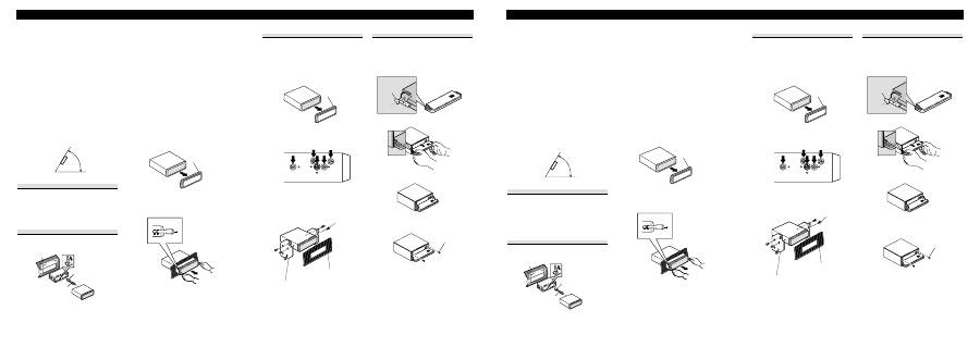
Trim ring
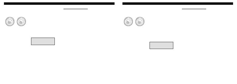
DIN Rear-mount
1. Extend top and bottom of the trim ring outwards
to remove the trim ring. When reattaching the
trim ring, push the trim ring onto the unit until it
clicks. (If the trim ring is attached upside down,
the trim ring will not fit properly.)
•
It becomes easy to remove the trim ring if the
front panel is released.
2. Determine the appropriate position where the
holes on the bracket and the side of the unit
match.
3. Tighten two screws on each side.
•
Use either truss screws (5 mm
×
8 mm) or
flush surface screws (5 mm
×
9 mm), depend-
ing on the shape of screw holes in the
bracket.
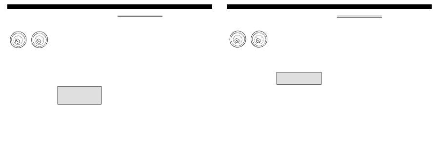
Fastening the front panel
If you do not plan to detach the front panel, the
front panel can be fastened with supplied screws
and holders.
1. Attach the holders to both sides of the front
panel.
2. Replace the front panel to the unit.
3. Flip the holders into upright positions.
4. Fix the front panel to the unit using screws.
Trim ring
Screw
Dashboard or Console
Factory radio mounting bracket
Rubber bush
Screw
Dashboard
Mounting sleeve
Screw
Holder
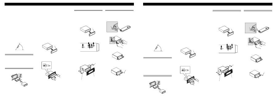
DIN Einbau an der Rückseite
1. Ziehen Sie den Zierleistenring an der Ober- und
Unterseite nach außen, um den Ring zu
entfernen. Beim erneuten Anbringen des
Zierleistenrings drücken Sie den Ring auf das
Gerät, bis er einrastet. (Falls der Zierleistenring
verkehrt herum angebracht wird, passt er nicht
richtig.)
•
Wenn die Frontplatte freigegeben ist, ist es
ganz einfach, den Zierleistenring
abzunehmen.
2. Bestimmen Sie die geeignete Position, wo die
Löcher in der Konsole und an der Geräteseite
übereinstimmen.
3.
Ziehen Sie zwei Schrauben auf jeder Seite fest.
•
Verwenden Sie entweder
Flachrundkopfschrauben (5 mm
×
8 mm)
oder Schrauben mit bündiger Oberfläche
(5 mm
×
9 mm), je nach der Art der
Schraubenlöcher in der Konsole.
Befestigung der Frontplatte
Falls Sie nicht beabsichtigen, die Frontplatte
abzunehmen, kann sie mit den mitgelieferten
Schrauben und Haltern befestigt werden.
1. Bringen Sie die Halter an beiden Seiten der
Frontplatte an.
2. Bringen Sie die Frontplatte weider am Gerät an.
3. Klappen Sie die Halter hoch.
4. Sichern Sie die Frontplatte mit den Schrauben
am Gerät.
Hinweise:
•
Überprüfen Sie alle Anschlüsse und Systeme,
bevor Sie das Gerät endgültig einbauen.
•
Verwenden Sie keine unautorisierten Teile. Die
Verwendung von unautorisierten Teilen kann zu
Funktionsstörungen führen.
•
Wenden Sie sich an Ihren Fachhändler, wenn
zum Einbau des Geräts Löcher gebohrt oder
andere Veränderungen an Ihrem Auto
vorgenommen wenden müssen.
•
Bauen Sie das Gerät nicht an einer Stelle ein, wo:
— es den Fahrer beim Fahren behindert.
— es den Beifahrer bei plötzlichem Bremsen
verletzen kann.
•
Der Halbleiterlaser wird bei Überhitzung
beschädigt. Bauen Sie das Gerät daher nicht an
einer Stelle ein, wo es heiß wird, z. B. in der
Nähe einer Heizungsauslassöffnung.
•
Die optimale Leistung wird erzielt, wenn der
Einbauwinkel nicht mehr als 60° beträgt.
DIN Einbau an der Vorderseite/Rückseite
Dieses Gerät kann entweder an der “Vorderseite”
(herkömmliche DIN Einbau an der Vorderseite)
oder an der “Rückseite” (DIN Einbau an der
Rückseite mit Hilfe der Löcher für die
Gewindeschrauben, die sich an der Seite des
Geräte-Chassis befinden) eingebaut werden.
Einzelheiten entnehmen Sie bitte den folgenden
Einbaumethoden.
DIN Einbau an der Vorderseite
Einbau mit der Gummibuchse
1. Setzen Sie den Halter in das Armaturenbrett ein.
•
Verwenden Sie beim Einbau an einer engen
Stelle einen mitgelieferten Halter. Wenn nicht
genügend Platz hinter dem Gerät vorhanden
ist, verwenden Sie den vom Werk
mitgelieferten Halter.
2. Befestigen Sie den Halter mit Hilfe eines
Schraubendrehers, um die Metalllaschen um 90°
zu verbiegen.
3. Bauen Sie das Gerät wie gezeigt ein.
Ausbauen des Geräts
1. Ziehen Sie den Zierleistenring an der Ober- und
Unterseite nach außen, um den Ring zu
entfernen. Beim erneuten Anbringen des
Zierleistenrings drücken Sie den Ring auf das
Gerät, bis er einrastet. (Falls der Zierleistenring
verkehrt herum angebracht wird, passt er nicht
richtig.)
•
Wenn die Frontplatte freigegeben ist, ist es
ganz einfach, den Zierleistenring
abzunehmen.
2. Setzen Sie die mitgelieferten Ausziehschlüssel
auf beiden Seiten bis zur Einrastposition in das
Gerät ein.
3. Ziehen Sie das Gerät aus dem Armaturenbrett.
53
53
1
1
182
182
60
°
Einbau DEUTSCH
Montaje trasero DIN
1. Extienda las partes superior e inferior del anillo
de compensación hacia fuera para extraer el anil-
lo de compensación. Cuando reinstale el anillo de
compensación, empuje el anillo de compensación
en la unidad hasta que encaje con un “clic”. (Si
se instala el anillo de compensación invertido,
puede que el anillo de compensación no se enca-
je correctamente.)
•
Se hace más fácil quitar el anillo de compen-
sación si se suelta el panel delantero.
2. Determine la posición apropiada donde los agu-
jeros en la ménsula y el lado de la unidad se
emparejan.
3. Apriete los dos tornillos en cada lado.
•
Utilice tornillos con cabeza ovalada (5 mm
×
8 mm) o tornillos de cabeza embutida (5 mm
×
9 mm), dependiendo de la forma de los
agujeros de tornillo en la ménsula.
Fijación del panel delantero
Si no planea extraer el panel delantero, se puede
fijar el panel delantero con los tornillos y sujeta-
dores suministrados.
1. Coloque los sujetadores en ambos lados del panel
delantero.
2. Reinstale el panel delantero en la unidad.
3. Mueva los sujetadores en las posiciones verti-
cales.
4. Fije el panel delantero a la unidad utilizando los
tornillos.
Nota:
•
Verifique todas las conexiones y sistemas antes
de la instalación final.
•
No utilice piezas no autorizadas. El uso de piezas
no autorizadas puede causar un fallo de
funcionamiento.
•
Consulte su revendedor si se requiere taladrar
agujeros o hacer otras modificaciones del
vehículo para la instalación.
•
No instale esta unidad donde:
— pueda interferir con la operación del vehículo.
— pueda causar lesiones a un pasajero en el caso
de una parada brusca.
•
El láser semiconductor se dañará si se sobre-
calienta. Instale esta unidad alejada de lugares
calientes como cerca de la salida del calentador.
•
Se obtiene el rendimiento óptimo cuando se
instala la unidad en un ángulo inferior a 60°.
Montaje delantero/trasero DIN
Se puede instalar esta unidad apropiadamente
mediante el montaje “delantero” (montaje delantero
DIN convencional) o montaje “trasero” (montaje
trasero DIN utilizando los agujeros de tornillo
roscados en los lados del bastidor de la unidad).
Para los detalles, consulte los siguientes métodos
de instalación.
Montaje delantero DIN
Instalación con el buje de caucho
1. Inserte el manguito de montaje en el tablero de
instrumentos.
•
Cuando instale en un lugar poco profundo, util-
ice el manguito de montaje suministrado. Si hay
espacio suficiente detrás de la unidad, utilice el
manguito de montaje suministrado de fábrica.
2. Fije el manguito de montaje utilizando un
destornillador para doblar las lengüetas de metal
(90°) en posición.
3. Instale la unidad como se muestra.
Extracción de la unidad
1. Extienda las partes superior e inferior del anillo
de compensación hacia fuera para extraer el
anillo de compensación. Cuando reinstale el anil-
lo de compensación, empuje el anillo de compen-
sación en la unidad hasta que encaje con un
“clic”. (Si se instala el anillo de compensación
invertido, puede que el anillo de compensación
no se encaje correctamente.)
•
Se hace más fácil quitar el anillo de compen-
sación si se suelta el panel delantero.
2. Inserte las llaves de extracción suministradas en
ambos lados de la unidad hasta que se enganchen
en posición.
3. Tire de la unidad del tablero de instrumentos.
53
53
1
1
182
182
60
°
Instalación ESPAÑOL
Tornillo
Tablero de instrumentos o consola
Ménsula de montaje de radio de fábrica
Buje de caucho
Tornillo
Manguito de montaje
Tablero de
instrumentos
Anillo de
compensación
Anillo de
compensación
Tornillo
Gummibuchse
Schraube
Halter
Armaturenbrett
Zierleistenring
Zierleistenring
Schraube
Armaturenbrett oder Konsole
Vom Werk mitgelieferter Radio-Befestigungsbügel
Schraube
Sujetador
Halter
Nota:
•
Prima dell’installazione finale vi raccomandiamo
di verificare tutti i sistemi coinvolti e le relative
connessioni.
•
Non fate mai uso di parti non autorizzate. Esse
potrebbero infatti dar luogo a malfunzionamenti.
•
Qualora l’installazione richieda l’esecuzione di
fori oppure di modifiche al veicolo, rivolgetevi
innanzi tutto al vostro rivenditore.
•
Non installate questa unità ove:
— possa interferire con la guida del veicolo.
— possa causare il ferimento dei passeggeri in
caso di brusca frenata.
•
Il laser a semiconduttore si potrebbe danneggiare
in caso di surriscaldamento. Installate pertanto
l’unità lontano dai punti ad elevata temperatura
quali, ad esempio, gli effusori del sistema di
riscaldamento del veicolo.
•
Le prestazioni migliori si ottengono quando
s’installa l’unità secondo un angolo di ampiezza
inferiore a 60°.
Installazione DIN frontale/posteriore
L’unità può essere correttamente installata sia su
“frontalmente” (normale installazione DIN
frontale) sia “posteriormente” (installazione DIN
posteriore impiegando i fori filettati ubicati sui
lati del telaio).
Le sezioni che seguono offrono informazioni
dettagliate sui due metodi d’installazione.
Installazione DIN frontale
Installazione con la guaina di gomma
1. Inserite nel cruscotto il telaio d’installazione.
•
Il telaio d’installazione va usato in caso
d’installazione in un punto poco profondo.
Qualora posteriormente all’unità vi sia
sufficiente spazio è raccomandabile impiegare
il telaio d’installazione del costruttore.
2. Fissate il telaio d’installazione usando un
cacciavite col quale piegare in posizione (di 90°)
le linguette metalliche.
3. Installate l’unità nel modo mostrato.
Rimozione dell’unità
1. Tirate verso l’esterno le parti superiore e
inferiore del bordo di rifinitura in modo da
rimuoverlo. Per rimontarlo premetelo nell’unità
sino ad avvertirne lo scatto in posizione (non
s’inserisce correttamente se si tenta di montarlo
capovolto).
•
La rimozione del bordo di rifinitura risulta
più facile quando si rimuove il pannello
anteriore.
2. Inserite in entrami i lati dell’unità le apposite
chiavi di estrazione sino ad avvertirne lo scatto in
posizione.
3. Estraete l’unità dal cruscotto.
53
53
1
1
182
182
60
°
Installazione ITALIANO
Montage arrière DIN
1. Étendez la partie supérieure et inférieure de la
garniture vers l’extérieur pour la retirer. Pour
fixer de nouveau la garniture, poussez la garni-
ture sur l’appareil jusqu’à ce qu’elle s’emboîte en
produisant un bruit sec. (Si la garniture est fixée
à l’envers, elle ne s’emboîte pas correctement).
•
Il est plus facile de retirer la garniture quand
le panneau avant est détaché.
2. Déterminez la position appropriée dans laquelle
les trous du support de montage coïncident avec
ceux du côté de l’appareil.
3. Serrez deux vis de chaque côté.
•
Utilisez des vis à tête bombée (5 mm
×
8 mm) ou des vis à tête encastrée (5 mm
×
9 mm), en fonction de la forme des trous dans
le support.
Fixation du panneau avant
Si vous ne prévoyez pas de détacher le panneau
avant, il peut être fixé avec les vis et les crochets
fournis.
1. Attachez les crochets des deux côtés de la face
avant.
2. Remettez la face avant en place sur l’appareil.
3. Faites pivoter les crochets en position droite.
4. Fixez la face avant sur l’appareil avec les vis.
Remarque:
•
Vérifiez toutes les connexions et tous les
systèmes avant l’installation finale.
•
N’utilisez aucune pièce non autorisée.
L’utilisation de pièces non autorisées peut causer
un mauvais fonctionnement.
•
Consultez votre revendeur si l’installation
nécessite que vous perciez des trous ou effectuiez
d’autres modifications du véhicule.
•
N’installez pas l’appareil dans un endroit où:
— il peut gêner la conduite du véhicule.
— il peut causer des blessures à un passager à la
suite d’un arrêt brutal.
•
Le laser à semi-conducteur sera endommagé en
cas de surchauffe. Installez cet appareil à l’écart
des endroits chauds tels que près de la sortie du
chauffage.
•
Des performances optimales peuvent être
obtenues quand l’appareil est installé avec un
angle de moins de 60°.
Montage avant/arrière DIN
Cet appareil peut être installé correctement par
“l’avant” (montage avant conventionnel DIN) ou
par “l’arrière” (montage par l’arrière DIN, en
utilisant les trous taraudés de chaque côté du
châssis). Pour les détails, reportez-vous aux
méthodes d’installation suivantes.
Montage avant DIN
Installation avec l’amortisseur en caoutchouc
1. Insérez le manchon de montage dans le tableau
de bord.
•
Si l’installation se fait dans un emplacement
étroit, utilisez le manchon de montage fourni.
S’il y a suffisamment de place derrière
l’appareil, utilisez le manchon de montage
fourni avec la voiture.
2. Fixez le manchon de montage en utilisant un
tournevis pour tordre les languettes de métal
(90°).
3. Installez l’appareil comme montré sur l’illustra-
tion.
Retrait de l’appareil
1. Étendez la partie supérieure et inférieure de la
garniture vers l’extérieur pour la retirer. Pour
fixer de nouveau la garniture, poussez la garni-
ture sur l’appareil jusqu’à ce qu’elle s’emboîte en
produisant un bruit sec. (Si la garniture est fixée
à l’envers, elle ne s’emboîte pas correctement).
•
Il est plus facile de retirer la garniture quand
le panneau avant est détaché.
2. Insérez les clés d’extraction fournies de chaque
côté de l’appareil jusqu’à ce que vous entendiez
un déclic.
3. Tirez l’appareil pour le sortir du tableau de bord.
53
53
1
1
182
182
60
°
Installation FRANÇAIS
Installazione DIN posteriore
1. Tirate verso l’esterno le parti superiore e inferi-
ore del bordo di rifinitura in modo da rimuoverlo.
Per rimontarlo premetelo nell’unità sino ad
avvertirne lo scatto in posizione (non s’inserisce
correttamente se si tenta di montarlo capovolto).
•
La rimozione del bordo di rifinitura risulta
più facile quando si rimuove il pannello
anteriore.
2. Determinate il punto esatto in cui i fori della
staffa e quelli ubicati ai lati dell’unità
coincidono.
3. Serrate bene due viti di entrambi i lati.
•
In funzione della forma dei fori filettati della
staffa usate viti a trave (5 mm
×
8 mm)
oppure viti incassate (5 mm
×
9 mm).
Fissaggio del pannello anteriore
Qualora non intendiate separare il pannello ante-
riore, esso può essere perennemente fissato con
le viti e i supporti forniti in dotazione.
1. Assicurare i supporti di fissaggio ad entrambi i
lati del pannello anteriore.
2. Rimontare il pannello anteriore sull’unità.
3. Ruotare i supporti nelle posizioni vertiali.
4. Bloccare il pannello anteriore all’unità per mezzo
delle apposite viti.
Amortisseur en
caoutchouc
Vis
Manchon de montage
Tableau de bord
Garniture
Garniture
Vis
Tableau de bord ou console
Support de montage fourni avec la voiture
Vis
Guaina di
gomma
Vite
Telaio d’installazione
Cruscotto
Bordo di rifinitura
Bordo di rifinitura
Vite
Cruscotto o console centrale
Staffa di montaggio radio del costruttore
Vite
Crochet
Supporto
ᇉÌ ÍÂÔÎÂÌË ÔÓ Òڇ̉‡ÚÛ DIN
1. éÚÚflÌËÚ ‚Âı Ë ÌËÁ ·ÒÚ˘ÌÓ„Ó Ó·Ó‰Í‡
̇ÛÊÛ, ˜ÚÓ·˚ ‚˚Ú‡˘ËÚ¸ „Ó. äÓ„‰‡ ÔÓ‚ÚÓÌÓ
ÔËÒÓ‰ËÌflÂÚ ·ÒÚ˘Ì˚È Ó·Ó‰ÓÍ, ‚‰‡‚ËÚ „Ó
‚ ÛÒÚÓÈÒÚ‚Ó, ÔÓ͇ ÓÌ Ì ˘ÂÎÍÌÂÚ. (ÖÒÎË
·ÒÚ˘Ì˚È Ó·Ó‰ÓÍ ÔËÒÓ‰ËÌÂÌ ‚ÂıÌÂÈ
ÒÚÓÓÌÓÈ ‚ÌËÁ, ÚÓ ÓÌ Ì ·Û‰ÂÚ ÔӉӄ̇Ì
‰ÓÎÊÌ˚Ï Ó·‡ÁÓÏ).
•
Ç˚Ú‡˘ËÚ¸ ·ÒÚ˘Ì˚È Ó·Ó‰ÓÍ Î„˜Â, ÂÒÎË
Ô‰Ìflfl Ô‡ÌÂθ ÓÔÛ˘Â̇.
2. èÓ‰·ÂËÚ ÔÓ‰ıÓ‰fl˘Â ÏÂÒÚÓ, „‰Â ÓÚ‚ÂÒÚËfl
̇ ÒÍÓ·Â Ë ÒÚÓÓÌ ÛÒÚÓÈÒÚ‚‡ ·Û‰ÛÚ
ÒÓ‚Ô‡‰‡Ú¸.
3. á‡ÚflÌËÚ ‰‚‡ ‚ËÌÚ‡ ̇ ͇ʉÓÈ ÒÚÓÓÌÂ.
•
àÒÔÓθÁÛÈÚ ‚ËÌÚ˚ ÒÓ ÒÙ¢ÂÒÍÓÈ
„ÓÎÓ‚ÍÓÈ (5 ÏÏ
×
8 ÏÏ) ËÎË ‚ËÌÚ˚ Ò
ÔÓÚ‡ÈÌÓÈ „ÓÎÓ‚ÍÓÈ (5 ÏÏ
×
9 ÏÏ), ‚
Á‡‚ËÒËÏÓÒÚË ÓÚ ÙÓÏ˚ ÓÚ‚ÂÒÚËÈ ‚ ÒÍÓ·Â.
á‡ÍÂÔÎÂÌË Ô‰ÌÂÈ Ô‡ÌÂÎË
ÖÒÎË ‚˚ Ì Ô·ÌËÛÂÚ ÓÚÒÓ‰ËÌflÚ¸ ÔÂÂ‰Ì˛˛
Ô‡ÌÂθ, ÚÓ Ó̇ ÏÓÊÂÚ ·˚Ú¸ Á‡ÍÂÔÎÂ̇ Ò
ÔÓÏÓ˘¸˛ ÔÓÒÚ‡‚ÎflÂÏ˚ı ‚ËÌÚÓ‚ Ë
‰ÂʇÚÂÎÂÈ.
1. á‡ÍÂÔËÚ ‰ÂʇÚÂÎË Ò Ó·ÂËı ÒÚÓÓÌ Ô‰ÌÂÈ
Ô‡ÌÂÎË.
2. èËÎÓÊËÚ ÔÂÂ‰Ì˛˛ Ô‡ÌÂθ Í ÛÒÚÓÈÒÚ‚Û.
3. è‚ÂÌËÚ ‰ÂʇÚÂÎË ‚ ‚ÂÚË͇θÌÓÂ
ÔÓÎÓÊÂÌËÂ.
4. èËÍÂÔËÚ ÔÂÂ‰Ì˛˛ Ô‡ÌÂθ Í ÛÒÚÓÈÒÚ‚Û,
ËÒÔÓθÁÛfl ‚ËÌÚ˚.
èËϘ‡ÌËÂ:
•
èӂ¸Ú ‚Ò ÒÓ‰ËÌÂÌËfl Ë ÒËÒÚÂÏ˚ Ô‰
ÓÍÓ̘‡ÚÂθÌÓÈ ÛÒÚ‡ÌÓ‚ÍÓÈ.
•
ç ËÒÔÓθÁÛÈڠ̇Á¯ÂÌÌ˚ ˜‡ÒÚË.
àÒÔÓθÁÓ‚‡Ìˠ̇Á¯ÂÌÌ˚ı ˜‡ÒÚÂÈ ÏÓÊÂÚ
ÒÚ‡Ú¸ Ô˘ËÌÓÈ ÌÂËÒÔ‡‚ÌÓÈ ‡·ÓÚ˚.
•
èÓÍÓÌÒÛθÚËÛÈÚÂÒ¸ Ò ‚‡¯ËÏ ‰ËÎÂÓÏ, ÂÒÎË
ÛÒÚ‡Ìӂ͇ Ú·ÛÂÚ ÔÓÒ‚ÂÎË‚‡ÌËfl ÓÚ‚ÂÒÚËÈ
ËÎË ‰Û„Ëı ÏÓ‰ËÙË͇ˆËÈ ‚‡¯Â„Ó
Ú‡ÌÒÔÓÚÌÓ„Ó Ò‰ÒÚ‚‡.
•
ç ÛÒڇ̇‚ÎË‚‡ÈÚ ÛÒÚÓÈÒÚ‚Ó Ú‡Ï, „‰Â:
— ÓÌÓ ÏÓÊÂÚ ÒÎÛÊËÚ¸ ÔÂÔflÚÒÚ‚ËÂÏ ‡·ÓÚ˚
Ú‡ÌÒÔÓÚÌÓ„Ó Ò‰ÒÚ‚‡.
— ÓÌÓ ÏÓÊÂÚ ÒÚ‡Ú¸ Ô˘ËÌÓÈ ÔÓ‚ÂʉÂÌËfl
Ô‡ÒÒ‡Êˇ ‚ ÂÁÛθڇÚ ‚ÌÂÁ‡ÔÌÓÈ ÓÒÚ‡ÌÓ‚ÍË.
•
èÓÎÛÔÓ‚Ó‰ÌËÍÓ‚˚È Î‡Á ·Û‰ÂÚ ÔÓ‚ÂʉÂÌ,
ÂÒÎË ÓÌ Ô„ÂÂÚÒfl. ìÒڇ̇‚ÎË‚‡ÈÚ ‰‡ÌÌÓÂ
ÛÒÚÓÈÒÚ‚Ó ‚‰‡ÎË ÓÚ „Ófl˜Ëı ÏÂÒÚ, Ú‡ÍËı ͇Í
fl‰ÓÏ Ò ‚˚ÔÛÒÍÓÏ Ì‡„‚‡ÚÂÎfl.
•
éÔÚËχθÌÓ ËÁÓ·‡ÊÂÌË Ì ÔÓÎÛ˜‡ÂÚÒfl,
ÍÓ„‰‡ ÛÒÚÓÈÒÚ‚Ó ÛÒÚ‡ÌÓ‚ÎÂÌÓ ÔÓ‰ Û„ÎÓÏ
ÏÂ̸¯Â ˜ÂÏ 60
°
.
è‰ÌÂÂ/ᇉÌ ÍÂÔÎÂÌË ÔÓ Òڇ̉‡ÚÛ DIN
äÂÔÎÂÌË ‰‡ÌÌÓ„Ó ÛÒÚÓÈÒÚ‚‡ ÏÓÊÌÓ
‚˚ÔÓÎÌflÚ¸ Í‡Í “ÒÔ‰˔ (Òڇ̉‡ÚÌÓÂ
ԉ̠ÍÂÔÎÂÌË DIN), Ú‡Í Ë “ÒÁ‡‰Ë”
(Á‡‰Ì ÍÂÔÎÂÌË DIN Ò ËÒÔÓθÁÓ‚‡ÌËÂÏ
ÂÁ¸·Ó‚˚ı ÓÚ‚ÂÒÚËÈ ‰Îfl ‚ËÌÚÓ‚,
‡ÒÔÓÎÓÊÂÌÌ˚ı ÔÓ ·ÓÍ‡Ï ‡Ï˚ ÛÒÚÓÈÒÚ‚‡).
ÅÓΠÔӉӷ̇fl ËÌÙÓχˆËfl Ô˂‰Â̇ ÌËÊÂ
‚ ËÎβÒÚËÓ‚‡ÌÌÓÏ ÓÔËÒ‡ÌËË ÏÂÚÓ‰Ó‚
ÛÒÚ‡ÌÓ‚ÍË.
è‰Ì ÍÂÔÎÂÌË ÔÓ Òڇ̉‡ÚÛ DIN
ìÒÚ‡Ìӂ͇ Ò ÂÁËÌÓ‚ÓÈ ‚ÚÛÎÍÓÈ
1. ÇÒÚ‡‚¸Ú ÏÓÌÚ‡ÊÌ˚È Û͇‚ ‚ ÔÂÂ‰Ì˛˛
Ô‡ÌÂθ.
•
äÓ„‰‡ ÛÒڇ̇‚ÎË‚‡ÂÚ ‚ Ì„ÎÛ·ÓÍÓÂ
ÔÓÒÚ‡ÌÒÚ‚Ó, ËÒÔÓθÁÛÈÚÂ
Ô‰ÛÒÏÓÚÂÌÌ˚È ÏÓÌÚ‡ÊÌ˚È Û͇‚. ÖÒÎË
ÔÓÁ‡‰Ë ÛÒÚÓÈÒÚ‚‡ ËÏÂÂÚÒfl ‰ÓÒÚ‡ÚÓ˜ÌÓÂ
ÔÓÒÚ‡ÌÒÚ‚Ó, ËÒÔÓθÁÛÈÚÂ
Ô‰ÛÒÏÓÚÂÌÌ˚È Á‡‚Ó‰ÓÏ ÏÓÌÚ‡ÊÌ˚È
Û͇‚.
2. á‡ÍÂÔËÚ ÏÓÌÚ‡ÊÌ˚È Û͇‚, ËÒÔÓθÁÛfl
ÓÚ‚ÂÚÍÛ, ˜ÚÓ·˚ ÒÓ„ÌÛÚ¸ ÏÂÚ‡Î΢ÂÒÍËÂ
Û¯ÍË (90
°
) ̇ ÏÂÒÚÓ.
3. ìÒÚ‡ÌÓ‚ËÚ ÛÒÚÓÈÒÚ‚Ó Í‡Í ÔÓ͇Á‡ÌÓ Ì‡
ËÎβÒÚ‡ˆËË.
쉇ÎÂÌË ìÒÚÓÈÒÚ‚‡
1. éÚÚflÌËÚ ‚Âı Ë ÌËÁ ·ÒÚ˘ÌÓ„Ó Ó·Ó‰Í‡
̇ÛÊÛ, ˜ÚÓ·˚ ‚˚Ú‡˘ËÚ¸ „Ó. äÓ„‰‡ ÔÓ‚ÚÓÌÓ
ÔËÒÓ‰ËÌflÂÚ ·ÒÚ˘Ì˚È Ó·Ó‰ÓÍ, ‚‰‡‚ËÚ „Ó
‚ ÛÒÚÓÈÒÚ‚Ó, ÔÓ͇ ÓÌ Ì ˘ÂÎÍÌÂÚ. (ÖÒÎË
·ÒÚ˘Ì˚È Ó·Ó‰ÓÍ ÔËÒÓ‰ËÌÂÌ ‚ÂıÌÂÈ
ÒÚÓÓÌÓÈ ‚ÌËÁ, ÚÓ ÓÌ Ì ·Û‰ÂÚ ÔӉӄ̇Ì
‰ÓÎÊÌ˚Ï Ó·‡ÁÓÏ).
•
Ç˚Ú‡˘ËÚ¸ ·ÒÚ˘Ì˚È Ó·Ó‰ÓÍ Î„˜Â, ÂÒÎË
Ô‰Ìflfl Ô‡ÌÂθ ÓÔÛ˘Â̇.
2. ÇÒÚ‡‚¸Ú Ô‰ÛÒÏÓÚÂÌÌ˚ Íβ˜Ë ‰Îfl
ËÁ‚ΘÂÌËfl ‚ Ó·Â ÒÚÓÓÌ˚ ÛÒÚÓÈÒÚ‚‡, ÔÓ͇
ÓÌË Ì Á‡˘ÂÎÍÌÛÚÒfl ̇ ÏÂÒÚÓ.
3. Ç˚ÚflÌËÚ ÛÒÚÓÈÒÚ‚Ó ËÁ Ô‰ÌÂÈ Ô‡ÌÂÎË.
53
53
1
1
182
182
60
°
ìÒÚ‡Ìӂ͇ PYCCKàâ
DIN Achter-montage
1. Buig de bovenkant en de onderkant van de
afwerkingsrand naar buiten om deze te
verwijderen. Druk de afwerkingsrand op het
toestel tot deze vastklikt wanneer u de
afwerkingsrand weer vast maakt. (Als de
afwerkingsrand ondersteboven gehouden wordt,
zal deze niet goed passen.)
•
De afwerkingsrand is makkelijker los te
maken wanneer het voorpaneel verwijderd is.
2. Bepaal welke gaatjes in de beugel en in de
zijkant van het toestel met elkaar overeenkomen.
3. Gebruik twee schroeven aan elke kant.
•
Gebruik schroeven met platte kop (5 mm
×
8
mm) of verzinkbare kop (5 mm
×
9 mm),
afhankelijk van de vorm van de
schroefgaatjes in de beugel.
Vastzetten van het voorpaneel
Als u het voorpaneel niet wilt kunnen
verwijderen, kunt u het vastzetten met de daartoe
meegeleverde schroeven en houders.
1. Bevestig de houders aan beide zijden van het
voorpaneel.
2. Plaats het voorpaneel weer op het toestel.
3. Klap de houders overeind.
4. Bevestig het voorpaneel met de schroeven aan
het toestel.
Opmerking:
•
Controleer alle aansluitingen en systemen voor
de uiteindelijke installatie.
•
Gebruik geen ongeautoriseerde onderdelen.
Gebruik van niet-goedgekeurde onderdelen kan
leiden tot storingen.
•
Raadpleeg uw dealer als u voor de installatie
gaten moet boren of andere wijzigingen aan het
voertuig zelf moet aanbrengen.
•
Installeer dit toestel in geen geval op een locatie waar:
— het de besturing van het voertuig kan
hinderen.
— het een passagier zou kunnen verwonden bij
een noodstop.
•
De halfgeleider laser zal kapot gaan als deze
oververhit raakt. Installeer dit toestel niet in de
buurt van zeer warme plekken, zoals bij een
verwarmingsrooster.
•
De optimale prestaties worden verkregen
wanneer het toestel geïnstalleerd wordt onder een
hoek van minder dan 60º.
DIN Voor/achter montage
Dit toestel kan op de juiste manier worden
vastgemaakt aan de voorkant (conventionele DIN
montage) of aan de achterkant (DIN
achtermontage, met behulp van de schroefgaatjes
aan de zijkanten van het chassis van het toestel).
Voor details verwijzen we u naar de volgende
installatiemethoden.
DIN Voor-montage
Installatie met het rubber tussenstuk
1. Steek de bevestigingskraag in het dashboard.
•
Gebruik een andere bevestigingskraag bij
installatie op een relatief ondiepe locatie. Als
er genoeg ruimte achter het toestel is, kunt u
de standaard meegeleverde bevestigingskraag
gebruiken.
2. Zet de bevestigingskraag vast door met behulp
van een schroevendraaier de metalen lipjes te
verbuigen (90º).
3. Installeer het toestel zoals u kunt zien op de
afbeelding.
Verwijderen van het toestel
1. Buig de bovenkant en de onderkant van de
afwerkingsrand naar buiten om deze te
verwijderen. Druk de afwerkingsrand op het
toestel tot deze vastklikt wanneer u de
afwerkingsrand weer vast maakt. (Als de
afwerkingsrand ondersteboven gehouden wordt,
zal deze niet goed passen.)
•
De afwerkingsrand is makkelijker los te
maken wanneer het voorpaneel verwijderd is.
2. Steek de meegeleverde ontgrendelingsstrips in
beide zijkanten van het toestel tot deze
vastklikken.
3. Trek het toestel uit het dashboard.
53
53
1
1
182
182
60
°
Installatie NEDERLANDS
Rubber
tussenstuk
Schroef
Bevestigingskraag
Dashboard
Afwerkingsrand
Afwerkingsrand
Schroef
Dashboard of console
Fabrieksmontagebeugel of-steun voor
bevestiging radio e.d.
Schroef
êÂÁËÌÓ‚‡fl ‚ÚÛÎ͇
ÇËÌÚ
åÓÌÚ‡ÊÌ˚È Û͇‚
è‰Ìflfl Ô‡ÌÂθ
ã‡ÒÚ˘Ì˚È
Ó·Ó‰ÓÍ
ã‡ÒÚ˘Ì˚È
Ó·Ó‰ÓÍ
ÇËÌÚ
è‰Ìflfl Ô‡ÌÂθ ËÎË ÍÓÌÒÓθ
ᇂӉÒ͇fl ÒÍÓ·‡ ‰Îfl ÍÂÔÎÂÌËfl
‡‰ËÓÔËÂÏÌË͇
ÇËÌÚ
Houder
ÑÂʇÚÂθ
Note:
•
When this unit is installed in a vehicle without
ACC (accessory) position on the ignition switch,
red cable must be wired to the terminal that can
detect the operation of the ignition key.
Otherwise, battery drain may result.
•
Use this unit in other than the following condi-
tions could result in fire or malfunction.
— Vehicles with a 12-volt battery and negative
grounding.
— Speakers with 50 W (output value) and 4 ohm
to 8 ohm (impedance value).
•
To prevent short-circuit, overheating or malfunc-
tion, be sure to follow the directions below.
— Disconnect the negative terminal of the bat-
tery before installation.
— Secure the wiring with cable clamps or adhe-
sive tape. To protect the wiring, wrap adhe-
sive tape around them where they lie against
metal parts.
— Place all cables away from moving parts,
such as gear shift and seat rails.
— Place all cables away from hot places, such as
near the heater outlet.
— Do not pass the yellow cable through a hole
into the engine compartment to connect to a
battery.
— Cover any disconnected cable connectors
with insulating tape.
— Do not shorten any cables.
— Never cut the insulation of the power cable of
this unit in order to share the power to other
equipment. Current capacity of the cable is
limited.
— Use a fuse of the rating prescribed.
— Never wire the speaker negative cable directly
to ground.
— Never band together multiple speaker’s nega-
tive cables.
•
Control signal is output through blue/white cable
when this unit is powered on. Connect it to an
external power amp’s system remote control or
the vehicle’s auto-antenna relay control terminal
(max. 300 mA, 12 V DC). If the vehicle is
equipped with a glass antenna, connect it to the
antenna booster power supply terminal.
•
Never connect blue/white cable to external power
amp’s power terminal. Also, never connect it to
the power terminal of the auto antenna.
Otherwise, battery drain or malfunction may
result.
•
IP-BUS connectors are color-coded. Be sure to
connect connectors of the same color.
•
Black cable is ground. This cable and other prod-
uct’s ground cable (especially, high-current prod-
ucts such as power amp) must be wired separate-
ly. Otherwise, fire or malfunction may result if
they are accidentally detached.
•
Cord function may differ according to the
product, even if cord color is the same. When
connecting this system, be sure to check all
manuals and connect cords correctly.
No ACC position
ACC position
ON
S
T
A
R
T
O
FF
ACC
ON
S
T
A
R
T
O
FF
+
+
+
+
≠
≠
≠
≠
1*
3*
2*
4*
5*
16.
Note:
Depending on the kind of vehicle,
the function of 3* and 5* may be
different. In this case, be sure to
connect 2* to 5* and 4* to 3*.
17. Connect leads of the same
color to each other.
18. Cap (1*)
Do not remove cap
if this terminal is
not in use.
19. Yellow (3*)
Back-up
(or
accessory)
21. Red (5*)
Accessory
(or back-up)
20. Yellow (2*)
Connect to the constant
12 V supply terminal.
22. Red (4*)
Connect to terminal controlled
by ignition switch (12 V DC).
23. Orange/white
Connect to lighting switch terminal.
25. ISO connector
Note:
In some vehicles, the ISO connector may
be divided into two. In this case, be sure
to connect to both connectors.
30. Speaker leads
White:
Front
left
+
White/black:
Front
left
≠
Gray:
Front
right
+
Gray/black:
Front
right
≠
Green:
Rear
left
+
or subwoofer
+
Green/black:
Rear
left
≠
or subwoofer
≠
Violet:
Rear
right
+
or subwoofer
+
Violet/black:
Rear
right
≠
or subwoofer
≠
31. Connect with RCA cables
(sold separately)
27. Blue/white
Connect to system control terminal of the
power amp (max. 300 mA 12 V DC).
28. Blue/white (7*)
Connect to auto-antenna relay control
terminal (max. 300 mA 12 V DC).
The pin position of the ISO connector will
differ depends on the type of vehicle. Connect
6* and 7* when Pin 5 is an antenna control
type. In another type of vehicle, never connect
6* and 7*.
37. Rear speaker
or
subwoofer
38. Perform these connections when
using the optional amplifier.
39.
Notes:
• Change the initial setting of this unit (refer to the Operation
Manual). The subwoofer output of this unit is monaural.
• When using a subwoofer of 70 W (2
Ω
) , be sure to connect
with Violet and Violet/black leads of this unit. Do not connect
anything with Green and Green/black leads.
26. Yellow/black
If you use an equipment with Mute
function, wire this lead to the Audio
Mute lead on that equipment. If not,
keep the Audio Mute lead free of any
connections.
Use a stereo mini plug cable
to connect with auxiliary
equipment.
24. Black (chassis ground)
Connect to a clean, paint-free metal location.
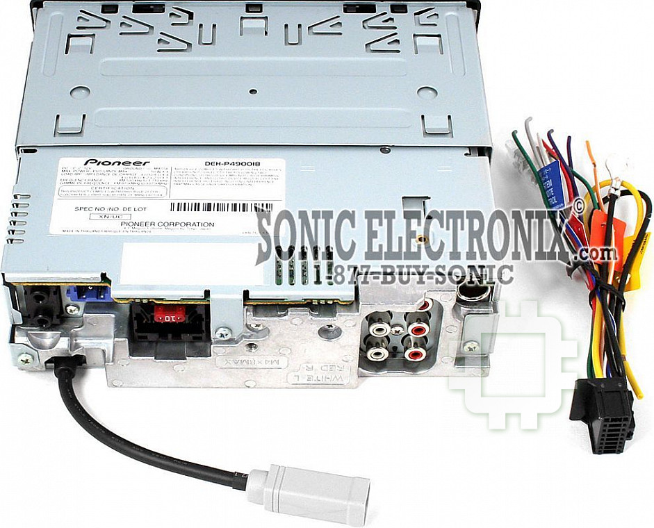
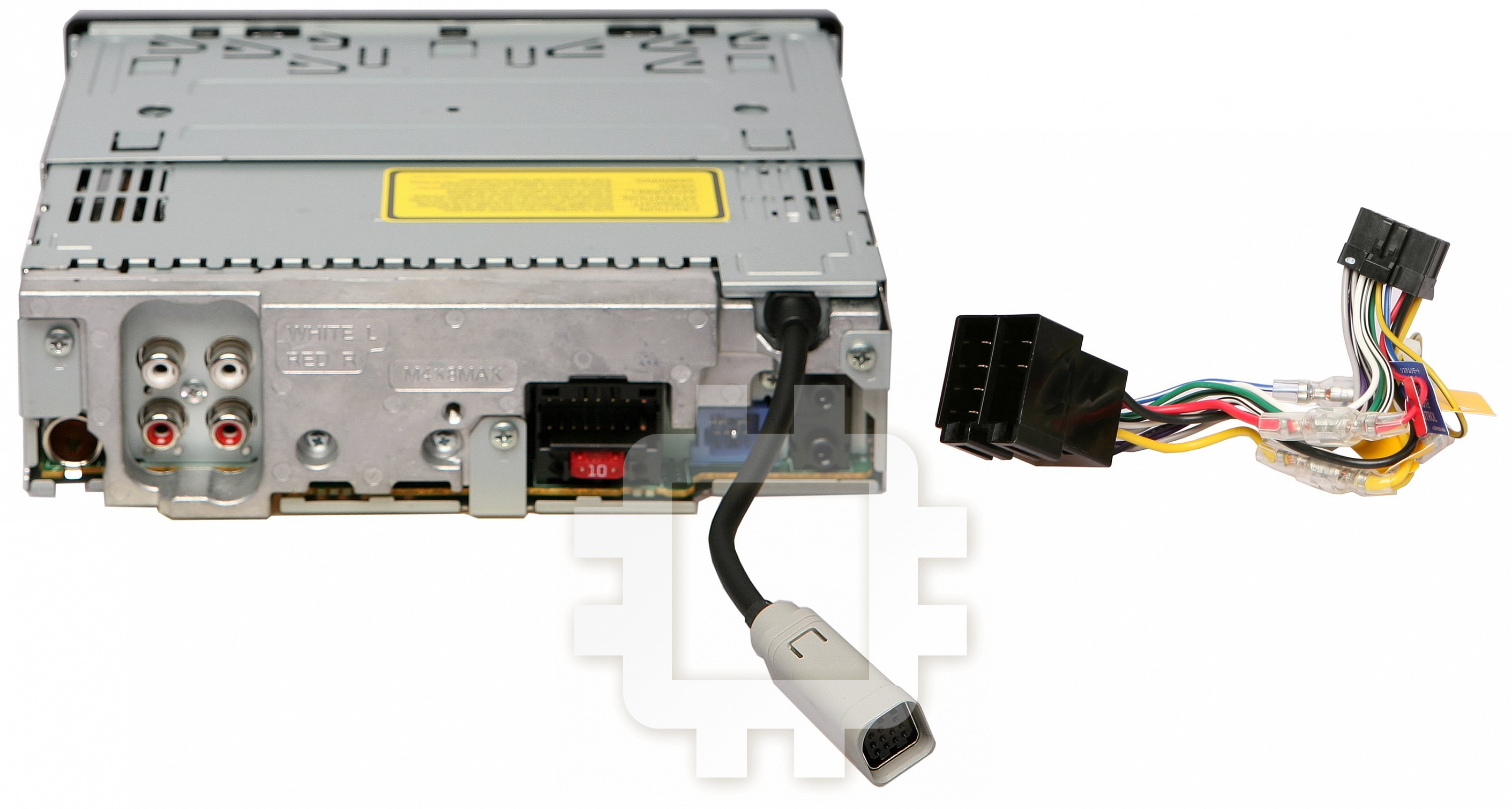
1. iPod with Dock
Connector
3. Dock connector port
2. Dock connector
4. Interface cable (e.g., CD-I200)
(sold separately)
2 m
6. This product
7. Rear output or
subwoofer output
9. Front output
8. Antenna jack
10. Fuse (10 A)
11. AUX jack (3.5 ø)
12. Wired remote input
Hard-wired remote control
adaptor can be connected
(sold separately).
13. IP-BUS
input (Blue)
14. IP-BUS cable
15. Multi-CD player
(sold separately)
32. Power amp
(sold separately)
32. Power amp
(sold separately)
33. System remote control
29. Blue/white (6*)
34. Front speaker
34. Front speaker
35.
Left
36.
Right
37. Rear speaker
or
subwoofer
15 cm
5. Gray
Connecting the Units ENGLISH
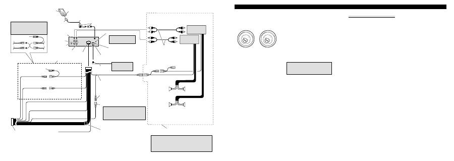
Connection Diagram
1. iPod with Dock Connector
2. Dock connector
3. Dock connector port
4. Interface cable (e.g., CD-I200) (sold separately)
5. Gray
6. This product
7. Rear output or subwoofer output
8. Antenna jack
9. Front output
10. Fuse (10 A)
11. AUX jack (3.5 ø)
Use a stereo mini plug cable to connect with
auxiliary equipment.
12. Wired remote input
Hard-wired remote control adaptor can be con-
nected (sold separately).
13. IP-BUS input (Blue)
14. IP-BUS cable
15. Multi-CD player (sold separately)
16. Note:
Depending on the kind of vehicle, the function of
3* and 5* may be different. In this case, be sure
to connect 2* to 5* and 4* to 3*.
17. Connect leads of the same color to each other.
18. Cap (1*)
Do not remove cap if this terminal is not in use.
19. Yellow (3*)
Back-up (or accessory)
20. Yellow (2*)
Connect to the constant 12 V supply terminal.
21. Red (5*)
Accessory (or back-up)
22. Red (4*)
Connect to terminal controlled by ignition switch
(12 V DC).
23. Orange/white
Connect to lighting switch terminal.
24. Black (chassis ground)
Connect to a clean, paint-free metal location.
25. ISO connector
Note:
In some vehicles, the ISO connector may be
divided into two. In this case, be sure to connect
to both connectors.
26. Yellow/black
If you use an equipment with Mute function,
wire this lead to the Audio Mute lead on that
equipment. If not, keep the Audio Mute lead free
of any connections.
27. Blue/white
Connect to system control terminal of the power
amp (max. 300 mA 12 V DC).
28. Blue/white (7*)
Connect to auto-antenna relay control terminal
(max. 300 mA 12 V DC).
29. Blue/white (6*)
The pin position of the ISO connector will differ
depends on the type of vehicle. Connect 6* and
7* when Pin 5 is an antenna control type. In
another type of vehicle, never connect 6* and 7*.
30. Speaker leads
White:
Front left
+
White/black: Front left
≠
Gray:
Front right
+
Gray/black:
Front right
≠
Green:
Rear left
+
or subwoofer
+
Green/black: Rear left
≠
or subwoofer
≠
Violet:
Rear right
+
or subwoofer
+
Violet/black: Rear right
≠
or subwoofer
≠
31. Connect with RCA cables (sold separately)
32. Power amp (sold separately)
33. System remote control
34. Front Speaker
35. Left
36. Right
37. Rear Speaker or subwoofer
38. Perform these connections when using the
optional amplifier.
39. Notes:
• Change the initial setting of this unit (refer to
the Operation Manual). The subwoofer output
of this unit is monaural.
• When using a subwoofer of 70 W (2
Ω
), be
sure to connect with Violet and Violet/black
leads of this unit. Do not connect anything with
Green and Green/black leads.
Nota:
•
Cuando se instale esta unidad en un vehículo sin
la posición ACC (accesorio) en el interruptor de
encendido, se debe conectar el cable rojo al ter-
minal que puede detectar la operación de la llave
de encendido.
De lo contrario, la batería puede descargarse.
•
El uso de esta unidad en condiciones diferentes
de las siguientes podría causar un fuego o fallo
de funcionamiento.
— Vehículos con una batería de 12 voltios y
puesta a tierra negativa.
— Altavoz con 50 W (valor de salida) y de 4 a 8
ohmios (valor de impedancia).
•
Para prevenir cortocircuitos, sobrecalentamiento
o fallo de funcionamiento, asegúrese de seguir las
instrucciones a continuación.
— Desenchufe el terminal negativo de la batería
antes de la instalación.
— Fije el cableado con abrazaderas de cable o
con cinta adhesiva. Para proteger el cableado,
envuélvalo con cinta adhesiva donde el
cableado se apoya sobre piezas metálicas.
— Posicione todos los cables alejados de las
piezas móviles, como el cambio de marchas y
rieles de los asientos.
— Posicione todos los cables alejados de lugares
calientes como cerca de la salida del calenta-
dor.
— No pase el cable amarillo a través de un agu-
jero en el compartimiento del motor para
conectar la batería.
— Cubra cualquier conector de cable desconec-
tado con cinta de aislamiento.
— No acorte ningún cable.
— No corte nunca el aislamiento del cable de
alimentación de esta unidad para compartir la
energía con otro equipo. La capacidad de cor-
riente del cable es limitada.
— Utilice un fusible con la capacidad especifica-
da.
— No conecte nunca el cable negativo de altavoz
directamente a la puesta a tierra.
— No junte nunca múltiples cables negativos de
altavoz.
•
La señal de control se emite a través del cable
azul/blanco cuando se enciende esta unidad.
Conéctelo a un terminal de control de sistema de
amplificador de potencia externo o al terminal de
control de relé de antena automática del vehículo
(máx. 300 mA, 12 V CC). Si el vehículo está
equipado con una antena de vidrio, conéctelo al
terminal de suministro de potencia de refuerzo de
la antena.
•
No conecte nunca el cable azul/blanco al termi-
nal de alimentación de un amplificador de poten-
cia externo. Igualmente, no conéctelo nunca al
terminal de alimentación de la antena automática.
De lo contrario, puede ocurrir la descarga de la
batería o un fallo de funcionamiento.
•
Los conectores IP-BUS están codificados en col-
ores. Asegúrese de conectar los conectores del
mismo color.
•
El cable negro es para la puesta a tierra. Se debe
conectar este cable y el cable de puesta a tierra
de otro producto (especialmente de productos de
alta corriente como un amplificador de potencia)
separadamente. De lo contrario, puede ocurrir un
fuego o fallo de funcionamiento si los cables se
sueltan accidentalmente.
Sin posición ACC
Posición ACC
ON
S
T
A
R
T
O
FF
ACC
ON
S
T
A
R
T
O
FF
Conexión de las unidades ESPAÑOL
Diagrama de conexión
1. iPod con conector del Dock
2. Conector del Dock
3. Puerto del conector del Dock
4. Cable de interfaz (e.g., CD-I200)
(vendido separadamente)
5. Gris
6. Este producto
7. Salida trasera o salida de altavoz de subgraves
8. Toma de antena
9. Salida delantera
10. Fusible (10 A)
11. Jack AUX (3.5 ø)
Utilice un cable con clavija mini estéreo con el
equipo auxiliar.
12. Entrada remota cableada
Se puede conectar el adaptador de control remoto
cableado (vendido separadamente).
13. Entrada IP-BUS (Azul)
14. Cable IP-BUS
15. Reproductor de Multi-CD (vendido separada-
mente)
16. Nota:
Dependiendo del tipo de vehículo, la función de
3* y 5* puede ser diferente. En este caso,
asegúrese de conectar 2* a 5* y 4* a 3*.
17. Conecte los hilos del mismo color a cada otro.
18. Tapa (1*)
No quite la tapa cuando no se utiliza este terminal.
19. Amarillo (3*)
Reserva (o accesorio)
20. Amarillo (2*)
Conecte el terminal de suministro de 12 V con-
stante.
21. Rojo (5*)
Accesorio (o reserva)
22. Rojo (4*)
Conecte al terminal controlado por del interrup-
tor de encendido (12 V CC).
23. Anaranjado/blanco
Conecte al terminal de interruptor de iluminación.
24. Negro (masa de la carrocería)
Conecte a un punto de metal limpio, libre de pin-
tura.
25. Conector ISO
Nota:
En algunos vehículos, puede que el conector ISO
esté dividido en dos. En este caso, asegúrese de
conectar a ambos conectores.
26. Amarillo/negro
Si se utiliza un equipo con función de
silenciamiento, conecte este conductor con el
conductor de silenciamiento de audio en tal
equipo. Si no, mantenga el enmudecimiento de
audio libre de cualquier conexión.
27. Azul/blanco
Conecte al terminal de control de sistema del
amplificador de potencia (máx. 300 mA 12 V
CC).
28. Azul/blanco (7*)
Conecte al terminal de control de relé de antena
automática (máx. 300 mA 12 V CC).
29. Azul/blanco (6*)
La posición de los contactos del conector ISO
difiere dependiendo del tipo del vehículo.
Conecte 6* y 7* cuando el contacto 5 es del tipo
de control de antena. En otros tipos de vehículo,
no conecte nunca 6* y 7*.
30. Hilos de altavoz
Blanco:
Izquierda delantera
+
Blanco/negro: Izquierda delantera
≠
Gris:
Derecha delantera
+
Gris/negro:
Derecha delantera
≠
Verde:
Izquierda trasera
+
o altavoz de subgraves
+
Verde/negro:
Izquierda trasera
≠
o altavoz de subgraves
≠
Violeta:
Derecha trasera
+
o altavoz de subgraves
+
Violeta/negro: Derecha trasera
≠
o altavoz de subgraves
≠
31. Conecte los cables RCA (vendidos separada-
mente)
32. Amplificador de potencia (vendido separada-
mente)
33. Control remoto de sistema
34. Altavoz delantero
35. Izquierda
36. Derecha
37. Altavoz trasero o altavoz de subgraves
38. Realice estas conexiones cuando utilice el ampli-
ficador opcional.
39. Notas:
• Cambie el ajuste inicial de esta unidad
(refiérase al manual de operación). La salida de
altavoz de subgraves de esta unidad es
monofónica.
• Cuando utilice un altavoz de subgraves de 70
W (2
Ω
), asegúrese de conectarlo con los hilos
Violeta y Violeta/negro de esta unidad. No
conecte nada con los hilos Verde y Verde/negro.
Hinweise:
•
Wenn dieses Gerät in einem Auto eingebaut wird,
as auf dem Zündschalter keine ACC (Zubehör)-
Position hat, sollte die rote Leitung des Geräts an
eine Klemme angeschlossen werden, die die
Position des Zündschalters erfassen kann.
Anderenfalls kann die Autobatterie entleert
werden.
•
Wenn das Gerät nicht unter den folgenden
Bedingungen eingebaut wird, kann ein Brand
oder eine Funktionsstörung auftreten.
— Fahrzeuge mit einer 12-Volt-Batterie und neg-
ativer Erdung.
— Lautsprecher mit 50 W (Ausgangsleistung)
und 4 bis 8 Ohm (Impedanz).
•
Um Kurzschlüsse, eine Überhitzung oder
Funktionsstörung zu verhindern, befolgen Sie
bitte die folgenden Hinweise:
— Trennen Sie die negative Klemme der
Batterie vor dem Einbau ab.
— Sichern Sie die Leitungen mit Kabelklemmen
oder Klebeband. Zum Schutz der Leitungen
sollten sie an Stellen, wo sie Metallteile
berühren, mit Klebeband umwickelt werden.
— Verlegen Sie alle Leitungen so, dass keine
beweglichen Teile, wie die Gangschaltung
und die Sitzschienen, berühren.
— Verlegen Sie alle Kabel so, dass sie von
heißen Stellen, wie etwa der
Heizungsauslassöffnung entfernt sind.
— Führen Sie die gelbe Leitung zum Anschluss
an die Batterie nicht durch ein Loch in den
Motorraum ein.
— Umwickeln Sie abgetrennte Leitungen mit
Isolierband.
— Verkürzen Sie keine Kabel.
— Führen Sie niemals anderen Geräten Strom
zu, indem Sie die Isolierung der
Stromversorgungsleitung dieses Geräts
durchschneiden und davon Strom abzapfen.
Die Strombelastbarkeit der Leitung ist
begrenzt.
— Verwenden Sie eine Sicherung mit dem
vorgeschriebenen Nennwert.
— Schließen Sie das negative Lautsprecherkabel
nie direkt an die Erdung an.
— Bündeln Sie nie die negativen Kabeln
mehrerer Lautsprecher.
•
Das Steuersignal wird über das blaue/weiße
Kabel ausgegeben, wenn dieses Geräts
eingeschaltet wird. Schließen Sie es an eine
System-Fernbedienung eines externen
Leistungsverstärkers oder an die
Autoantennenrelais-Steuerungsklemme des
Fahrzeugs an (max. 300 mA, 12 V
Gleichspannung). Wenn das Fahrzeug mit einer
Fensterantenne ausgestattet ist, schließen Sie es
an die Antennenverstärker-
Stromversorgungsklemme an.
•
Schließen Sie das blaue/weiße Kabel nie an die
Leistungsklemme des Verstärkers an. Außerdem
darf das blaue/weiße Kabel nicht an die
Leistungsklemme der Auto-Antenne
angeschlossen werden. Ein solcher Anschluss
könnte zu einer Belastung der Batterie führen
und Funktionsstörungen verursachen.
•
Die IP-BUS-Leitungen sind farbcodiert. Achten
Sie immer darauf, Leitungen derselben Farbe
miteinander zu verbinden.
•
Das schwarze Kabel ist das Erdungskabel. Dieses
Kabel ist getrennt von der Erde von Hochstrom-
Geräten, wie z. B. Leistungsverstärkern, zu
erden. Anderenfalls besteht die Gefahr einer
Beschädigung der Geräte oder eines Brandes,
falls die Erdungsstelle versehentlich abgetrennt
wird.
•
Die Kabelfunktion kann je nach Produkt
verschieden sein, selbst wenn die Farbe der
Kabel dieselbe ist. Beachten Sie daher alle
Bedienungsanleitungen, und schließen Sie die
Kabel korrekt an.
Keine ACC-Position
ACC-Position
ON
S
T
A
R
T
O
FF
ACC
ON
S
T
A
R
T
O
FF
Anschließen der Geräte
Anschlussdiagramm
1. iPod mit Dock-Anschlussstecker
2. Dock-Anschlussstecker
3. Dock-Anschluss
4. Schnittstellenkabel (z. B. CD-I200)
(getrennt erhältlich)
5. Grau
6. Dieses Produkt
7. Ausgang für hintere Zusatzlautsprecher oder
Subwoofer-Ausgang
8. Antennebuchse
9. Ausgang für vorderen Zusatzlautsprecher
10. Sicherung (10 A)
11. AUX-Buchse (3.5 ø)
Zur Verbindung mit Zusatzausrüstung verwenden
Sie ein Stereo-Ministeckerkabel.
12. Buchse für die verdrahtete Fernbedienung
Hier kann ein Drahtfernbedienungsadapter
(getrennt erhältlich) angeschlossen werden.
13. IP-BUS-Eingang (Blau)
14. IP-BUS-Kabel
15. Multi-CD-Player (getrennt erhältlich)
16. Hinweis:
Je nach Art des Fahrzeugs besitzen 3* und 5*
u. U. unterschiedliche Funktionen. Verbinden Sie
in einem solchen Fall 2* mit 5* und 4* mit 3*.
17. Verbinden Sie Leitungen derselben Farbe
miteinander.
18. Kappe (1*)
Wenn dieser Steckverbinder nicht verwendet
wird, lassen Sie die Kappe aufgesetzt.
19. Gelb (3*)
Reserve (oder Zubehör)
20. Gelb (2*)
An eine Stromversorgung anschließen, die immer
Gleichstrom von 12 V führt.
21. Rot (5*)
Zubehör (oder Reserve)
22. Rot (4*)
An eine Stromversorgung anschließen, (12 V
Gleichspannung), die mit dem Zündschloss ein-
/ausgeschaltet wird.
23. Orangefarben/weiß
An die Lichtschalterklemme anschließen.
24. Schwarz (Erdung)
An ein sauberes Metallteil anschließen, das von
Farbe frei ist.
25. ISO-Anschluss
Hinweis:
Bei einigen Fahrzeugen kann der ISO-
Steckverbinder in zwei Hälften geteilt sein. In
diesem Fall ist der Anschluss unbedingt an
beiden Steckverbindern vorzunehmen.
26. Gelb/schwarz
Falls Sie ein Gerät mit Stummschaltfunktion
(Mute) verwenden, verdrahten Sie dieses Kabel
mit der Audio Mute-Leitung am entsprechenden
Gerät. Andernfalls die Audio Mute-Leitung frei
von Anschlüssen lassen.
27. Blau/weiß
An den Systemsteuerungs-Anschluss des
Leistungsverstärkers (max. 300 mA, 12 V
Gleichspannung) anschließen.
28. Blau/weiß (7*)
An die die Autoantennenrelais-
Steuerungsklemme anschließen (max. 300 mA,
12 V Gleichspannung).
29. Blau/weiß (6*)
Die Pin-Position des ISO-Anschlusses hängt vom
Fahrzeugtyp ab. 6* und 7* anschließen, wenn es
sich bei Pin 5 um einen Antennensteuerungstyp
handelt. Bei einem anderen Fahrzeugtyp 6* und
7* niemals anschließen.
30. Lautsprecherzuleitungen
Weiß:
Vorne links
+
Weiß/Schwarz:
Vorne links
≠
Grau:
Vorne rechts
+
Grau/Schwarz:
Vorne rechts
≠
Grün:
Hinten links
+
oder Subwoofer
+
Grün/Schwarz:
Hinten links
≠
oder Subwoofer
≠
Violett:
Hinten rechts
+
oder Subwoofer
+
Violett/Schwarz: Hinten rechts
≠
oder Subwoofer
≠
31. Mit RCA-Kabeln verbinden (getrennt erhältlich)
32. Leistungsverstärker (getrennt erhältlich)
33. System-Fernbedienung
34. Vorderer Lautsprecher
35. Links
36. Recht
37. Hinterer Lautsprecher oder Subwoofer
38. Bei Gebrauch des optionalen Verstärkers diese
Anschlüsse vornehmen.
39. Hinweise:
• Ändern Sie die Grundeinstellung dieses Geräts
(siehe Bedienungsanleitung). Der Subwoofer-
Ausgang dieses Geräts ist Mono.
• Bei Verwendung eines Subwoofers von 70 W
(2
Ω
) achten Sie darauf, den Anschluss an die
violetten und violetten/schwarzen Leitungen
dieses Geräts herzustellen. Stellen Sie keinen
Anschluss mit den grünen und
grünen/schwarzen Leitungen her.
DEUTSCH
•
La función del cable puede diferir de acuerdo
con el producto, aunque el color del cable sea
igual. Cuando conecte este sistema, asegúrese
de verificar todos los manuales y conecte los
cables correctamente.
Remarque:
•
Si cet appareil est installé dans un véhicule sans
position ACC (accessoire) sur le commutateur
d’allumage, le câble rouge doit être connecté à
une borne qui peut détecter la position du com-
mutateur d’allumage. Sinon, la batterie risque de
se décharger.
•
Utiliser cet appareil dans d’autres conditions que
les conditions suivantes peut entraîner un
incendie ou un mauvais fonctionnement.
— Véhicule avec une batterie de 12 volts et une
mise à la masse négative.
— Enceintes de 50 W (valeur de sortie) et de 4
ohms à 8 ohms (valeur d’impédance).
•
Pour éviter tout court-circuit, surchauffe ou mau-
vais fonctionnement, assurez-vous de suivre les
instructions ci-dessous.
— Déconnectez la borne négative de la batterie
avant l’installation.
— Fixez solidement les câbles avec des serre-
câbles ou du ruban adhésif. Pour protéger le
câblage, entourez-le de ruban adhésif à l’en-
droit où il est en contact avec des pièces
métalliques.
— Tenez tous les câbles à l’écart des parties
mobiles, telles que le levier de vitesse et les
rails des sièges.
— Tenez tous les câbles à l’écart des endroits
chauds, tels que les sorties du chauffage.
— Ne faites pas passer le câble jaune par un trou
dans le compartiment du moteur pour le con-
necter à la batterie.
— Recouvrez tous les câbles non connectés avec
du ruban isolant.
— Ne raccourcissez aucun câble.
— Ne coupez jamais l’isolant du câble d’alimen-
tation de cet appareil afin partager l’alimenta-
tion avec un autre appareil. La capacité élec-
trique du câble est limitée.
— Utilisez un fusible de la valeur donnée.
— Ne connectez jamais le câble négatif des
enceintes directement à la masse.
— N’attachez jamais ensemble plusieurs câbles
négatifs de plusieurs enceintes.
•
Le signal de commande est sorti par le câble
bleu/blanc quand cet appareil est sous tension.
Connectez-le à la télécommande d’un système
d’amplification extérieur ou à la prise de com-
mande du contrôle de relais de l’antenne automa-
tique (max. 300 mA, 12 V CC). Si le véhicule est
équipée d’une antenne de vitre, connectez-la à la
prise d’alimentation de l’amplificateur d’antenne.
•
Ne connectez jamais le câble bleu/blanc à la
prise d’alimentation d’un amplificateur extérieur.
Et ne le connectez pas à la prise d’alimentation
de l’antenne automatique. Sinon, la batterie
risque de se décharger ou un mauvais fonction-
nement peut se produire.
•
Les connecteurs IP-BUS sont codés par couleur.
Assurez-vous de connecter les connecteurs de
même couleur.
•
Le câble noir est pour la masse. Ce câble et les
câbles de masse des autres produits (en particuli-
er les appareils à haute intensité tels que les
amplificateurs) doivent être câblés séparément.
Sinon, ils peuvent entraîner un incendie ou un
mauvais fonctionnement s’ils se détachent.
•
La fonction des câbles peut différer en fonc-
tion de l’appareil, même si la couleur est la
même. Lors de la connexion de ce système,
assurez-vous de vérifier tous les manuels et
de connecter les câbles correctement.
Pas de position ACC
Position ACC
ON
S
T
A
R
T
O
FF
ACC
ON
S
T
A
R
T
O
FF
Diagramme de connexion
1. iPod avec connecteur Dock
2. Connecteur Dock
3. Port de connexion Dock
4. Câble d’interface (par ex., CD-I200)
(vendu séparément)
5. Gris
6. Cet appareil
7. Sortie arrière ou sortie du caisson de grave
8. Prise d’antenne
9. Sortie avant
10. Fusible (10 A)
11. Prise AUX (3.5 ø)
Utilisez un câble à fiches stéréo mini pour
raccorder un appareil auxiliaire.
12. Entrée de télécommande câblée
Un adaptateur de télécommande câblée peut être
connecté (vendu séparément).
13. Entrée IP-BUS (Bleu)
14. Câble IP-BUS
15. Lecteur de CD à chargeur (vendu séparément)
16. Remarque:
En fonction du type de véhicule, la fonction de
3* et de 5* peut différer. Sans ce cas, assurez-
vous de connecter 2* à 5* et 4* à 3*.
17. Connectez les câbles de la même couleur les uns
aux autres.
18. Capuchon (1*)
Ne retirez pas le capuchon si cette prise n’est pas
utilisée.
19. Jaune (3*)
Secours (ou accessoire)
20. Jaune (2*)
Connectez à une prise d’alimentation constante
12 V.
21. Rouge (5*)
Accessoire (ou secours)
22. Rouge (4*)
Connectez à une prise commandée par le com-
mutateur d’allumage (12 V CC).
23. Orange/blanc
Connectez à la prise du commutateur d’éclairage.
24. Noire (masse au châssis)
Connectez à une section métallique propre et
sans peinture.
25. Connecteur ISO
Remarque:
Dans certains véhicule, le connecteur ISO peut
être divisé en deux. Dans ce cas, assurez-vous de
faire la connexion aux deux connecteurs.
26. Jaune/noir
Si vous utilisez un appareil muni d’une fonction
de mise en sourdine, connectez ce conducteur au
conducteur de sourdine audio de cet appareil.
Sinon, laisser le fil de mise en sourdine audio
sans aucune connexion.
27. Bleu/blanc
Connectez à la prise de commande du système de
l’amplificateur de puissance (max. 300 mA 12 V
CC).
28. Bleu/blanc (7*)
Connectez à la prise du contrôle de relais de l’an-
tenne automatique (max. 300 mA, 12 V CC).
29. Bleu/blanc (6*)
La position des broches du connecteur ISO dif-
fère en fonction du type de véhicule. Connectez
6* et 7* quand la broche 5 correspond à la com-
mande de l’antenne. Dans les autres cas, ne con-
nectez jamais 6* et 7*.
30. Câbles d’enceinte
Blanc:
Avant gauche
+
Blanc/noir:
Avant gauche
≠
Gris:
Avant droit
+
Gris/noir:
Avant droit
≠
Vert:
Arrière gauche
+
ou caisson de grave
+
Vert/noir:
Arrière gauche
≠
ou caisson de grave
≠
Violet:
Arrière droit
+
ou caisson de grave
+
Violet/noir:
Arrière droit
≠
ou caisson de grave
≠
31. Connectez aux câbles cinch (RCA) (vendus
séparément)
32. Amplificateur de puissance (vendu séparément)
33. Télécommande du système
34. Enceinte avant
35. Gauche
36. Droit
37. Enceinte arrière ou caisson de grave
38. Réalisez ces connexions lors de l’utilisation de
l’amplificateur en option.
39. Remarques:
• Change le réglage initial de cet appareil
(reportez-vous aux mode d’emploi). La sortie
de caisson de grave de cet appareil est mono-
phonique.
• Lors de l’utilisation d’un caisson de grave de
70 W (2
Ω
), assurez-vous de le raccorder aux
câbles Violet et Violet/noir de cet appareil. Ne
connectez rien aux câbles Vert et Vert/noir.ir.
FRANÇAIS Connexions des appareils
Nota:
•
Qualora l’unità venga installata in un veicolo la
cui chiavetta di accensione è sprovvista della
posizione ACC (accessori), il cavo rosso deve
essere collegato al terminale in grado di rilevare
il funzionamento della chiavetta stessa.
In caso contrario la batteria si scaricherebbe.
•
L’impiego dell’unità in condizioni diverse dalle
seguenti potrebbe dar luogo a incendi o malfun-
zionamenti:
— Veicoli provvisti di batteria da 12 V con
messa a terra sul negativo.
— Altoparlanti da 50 W (uscita) e da 4 ohm a
8 ohm (impedenza)
•
Per impedire il verificarsi di cortocircuiti, di sur-
riscaldamento o di malfunzionamenti raccoman-
diamo di osservare le seguenti istruzioni.
— Prima di procedere con l’installazione scolle-
gate il terminale negativo della batteria.
— Bloccate i cavi con apposite fascette o con del
nastro adesivo. Per proteggere i cavi che scor-
rono contro le parti metalliche del veicolo
avvolgeteli inoltre con del nastro adesivo.
— Allontanate tutti i cavi da qualsiasi parte in
movimento quali, ad esempio, la leva del
cambio e le guide dei sedili.
— Allontanate tutti i cavi da punti ad elevata
temperatura quali, ad esempio, gli effusori del
sistema di riscaldamento del veicolo.
— Per collegare il cavo giallo alla batteria non
fatelo passare per un foro ricavato nella strut-
tura di separazione dal vano del motore.
— Proteggete con del nastro adesivo tutti i con-
nettori non usati.
— Non accorciate alcun cavo di collegamento.
— Non tagliate la guaina d’isolamento del cavo
di alimentazione di questa unità in modo da
prelevare corrente per alimentare altri
apparecchi. La capacità di corrente di questo
cavo è infatti limitata.
— Usate solo un fusibile della capacità prescrit-
ta.
— Non collegate mai direttamente a terra il cavo
negativo degli altoparlanti.
— Non raggruppate fra loro il cavo negativo di
più altoparlanti.
•
Quando l’unità è accesa il segnale di controllo è
posto in uscita attraverso il cavo blu/bianco.
Collegatelo al telecomando di un amplificatore di
potenza esterno o al terminale di controllo del
relé dell’antenna automatica del veicolo (massi-
mo 300 mA e 12 V CC). Se il veicolo è provvisto
di un’antenna a vetro collegatela al terminale di
alimentazione del relativo booster.
•
Non collegate il cavo blu/bianco al terminale di
alimentazione dell’amplificatore di potenza ester-
no. Non collegatelo inoltre al terminale di ali-
mentazione dell’antenna.
In caso contrario la batteria si scaricherebbe
oppure si potrebbero verificare dei malfunziona-
menti.
•
I connettori IP-BUS sono codificati a colore. È
pertanto necessario collegarli a connettori dello
stesso colore.
•
Il cavo nero va usato solo per la messa a terra.
Questo cavo e il cavo di messa a terra di altri
apparecchi (in particolare quelli ad alta corrente
quali gli amplificatori di potenza) devono essere
collegati separatamente.
In caso contrario, qualora si scolleghino acciden-
talmente, si potrebbero verificare incendi o mal-
funzionamenti.
•
La funzione dei cavi può differire da prodotto
a prodotto anche a parità di colore. Prima di
collegare questo sistema consultate tutti i
manuali di pertinenza ed accertatevi che tutti i
cavi siano correttamente collegati.
Assenza di posizione ACC
Posizione ACC
ON
S
T
A
R
T
O
FF
ACC
ON
S
T
A
R
T
O
FF
Collegamento delle unità
Schema di collegamento
1. iPod con connettore Dock
2. Connettore Dock
3. Porta connettore Dock
4. Cavo d’interfaccia (ad esempio il CD-I200)
(venduto a parte)
5. Grigio
6. Questo apparecchio
7. Uscita posteriore o uscita del subwoofer
8. Presa d’antenna
9. Uscita anteriore
10. Fusibile (10 A)
11. Presa AUX (3.5 ø)
Per il collegamento all’apparecchio ausiliario
utilizzate un cavo con spina stereo mini.
12. Ingresso del telecomando a filo
Qui si collega l’adattatore del telecomando a filo
(venduto a parte).
13. Ingresso IP-BUS (Blu)
14. Cavo IP-BUS
15. Multilettore CD (venduto separatamente)
16. Nota:
In funzione del tipo di veicolo le funzione di 3* e
di 5* potrebbe differire. In tal caso collegare 2* a
5* e 4* a 3*.
17. Collegare fra loro i cavi di uguale colore.
18. Capocorda (1*)
Non deve essere rimosso quando non si impiega
questo connettore.
19. Giallo (3*)
Retromarcia (o accessorio)
20. Giallo (2*)
Da collegare al terminale costantemente alimen-
tato a 12 V.
21. Rosso (5*)
Accessorio (o retromarcia)
22. Rosso (4*)
Da collegare al terminale controllato dalla
chiavetta di accensione (12 V CC).
23. Arancione/bianco
Collegare al terminale dell’interruttore d’illumi-
nazione.
24. Nero (messa a terra sulla carrozzeria)
Da collegare in un punto metallico pulito e non
verniciato.
25. Connettore ISO
Nota:
In alcuni veicoli il connettore ISO potrebbe
essere separato in due. In tal caso è necessario
collegare entrambi.
26. Giallo/nero
Questo cavo deve essere collegato al cavo di
silenziamento audio dell’apparecchio provvisto
della funzione di silenziamento, qualora sia
effettivamente utilizzato. In caso contrario, non
collegare affatto il cavo di selinziamento audio.
27. Blu/bianco
Da collegare al terminale di controllo di sistema
dell’amplificatore di potenza (massimo 300 mA
12 V CC).
28. Blu/bianco (7*)
Da collegare al terminale di controllo del relé
dell’antenna automatica (massimo 300 mA
12 V CC).
29. Blu/bianco (6*)
La posizione dei contatti del connettore ISO può
differire in funzione del tipo di veicolo. Collegare
6* e 7* qualora il contatto 5 sia del tipo per con-
trollo dell’antenna. In altri tipi di veicolo 6* e 7*
non devo mai essere collegati.
30. Cavi altoparlanti
Bianco:
Anteriore sinistro
+
Bianco/nero: Anteriore sinistro
≠
Grigio:
Anteriore destro
+
Grigio/nero: Anteriore destro
≠
Verde:
Posteriore sinistro
+
o subwoofer
+
Verde/nero:
Posteriore sinistro
≠
o subwoofer
≠
Viola:
Posteriore destro
+
o subwoofer
+
Viola/nero:
Posteriore destro
≠
o subwoofer
≠
31. Da collegare ai cavi RCA (venduti a parte)
32. Amplificatore di potenza (venduto a parte)
33. Telecomando del sistema
34. Diffusore anteriore
35. Sinistra
36. Destra
37. Diffusore posteriore o subwoofer
38. Questi collegamenti devono essere eseguiti quan-
do s’impiega l’amplificatore opzionale.
39. Note:
• Cambiare l’impostazione iniziale di questa
unità (far riferimento al manuale d’istruzioni
per l’uso). L’uscita subwoofer di questa unità è
di tipo mono.
• Se s’impiega un subwoofer da 70 W (2
Ω
) è
necessario collegarlo con i cavi viola e
viola/nero di questa unità. Nulla deve invece
essere collegato con i cavi verde e verde/nero.
ITALIANO
Opmerking:
•
Wanneer dit toestel geïnstalleerd is in een
voertuig zonder ACC (accessoire) stand op het
contactslot, moet de rode draad worden
verbonden met een aansluiting die de stand van
de contactsleutel kan herkennen.
Anders kan de accu leeglopen.
•
Gebruik van dit toestel onder andere dan de
volgende omstandigheden kan leiden tot brand of
storingen.
— Voertuigen met een negatief geaarde 12 V
accu.
— Luidsprekers van 50 W (uitgangsvermogen)
en 4 Ohm tot 8 Ohm (impedantie).
•
Om kortsluiting, oververhitting of andere
storingen te voorkomen moet u de onderstaande
instructies opvolgen.
— Koppel de negatieve pool van de accu los
voor u begint met de installatie.
— Zet alle bedrading vast met kabelklemmen of
isolatieband. Ter bescherming van de
bedrading dient u deze te omwikkelen met
isolatieband waar de bedrading met metalen
onderdelen in aanraking komt.
— Houd alle bedrading uit de buurt van
bewegende onderdelen, zoals de
versnellingspook en de stoelenrails.
— Houd de bedrading uit de buurt van zeer
warme plekken, zoals bij een
verwarmingsrooster.
— Leid de gele draad niet door een gat naar het
motorcompartiment om aan te sluiten op de
accu.
— Plak eventuele losse aansluitingen,
draadeinden of stekkers netjes af met
isolatieband.
— Maak de kabels niet korter.
— Tap in geen geval de stroomkabel voor dit
toestel af om andere apparatuur van stroom te
voorzien. Het vermogen van de draad is
beperkt.
— Gebruik een zekering met het voorgeschreven
vermogen.
— Sluit de negatieve luidsprekerdraden in geen
geval direct op aarde aan.
— Bundel de negatieve luidsprekerdraden in
geen geval samen.
•
Via de blauw/witte draad wordt een stuursignaal
geproduceerd wanneer dit toestel is ingeschakeld.
Verbind deze met de systeemafstandsbediening
van een externe eindversterker, of met de
stuuraansluiting voor het relais van de antenne
van het voertuig (max. 300 mA, 12 V
gelijkstroom). Als het voertuig een ruitantenne
heeft, dient u deze draad te verbinden met de
stroomaansluiting van de
antennesignaalversterker (booster).
•
Verbind de blauw/witte draad in geen geval met
de stroomaansluiting van een externe
eindversterker. Verbind deze draad ook in geen
geval met de stroomaansluiting zelf van de
antenne van de auto. Doet u dit toch, dan kan de
accu leeglopen of kunnen zich andere storingen
voordoen.
•
IP-BUS stekkers zijn kleurgecodeerd. Let erop
dat u alleen stekkers van dezelfde kleur op elkaar
aansluit.
•
De zwarte draad is de aarding. Deze draad en de
aardingen van andere apparatuur (in het bijzonder
producten met een hoog vermogen, zoals een
eindversterker), moeten onafhankelijk van elkaar
worden aangesloten. Doet u dit niet, dan kan er
brand ontstaan of kunnen zich storingen
voordoen wanneer de bedrading onbedoeld los
raakt.
•
De functies van de draden zijn afhankelijk
van het product waar ze bij horen, ook al
hebben ze dezelfde kleuren als andere draden.
Controleer daarom bij het aansluiten van dit
systeem alle handleidingen van de betrokken
apparatuur zodat u er zeker van kunt zijn dat
u de bedrading correct aansluit.
Geen ACC stand
ACC stand
ON
S
T
A
R
T
O
FF
ACC
ON
S
T
A
R
T
O
FF
Aansluitingsschema
1. iPod met Dockconnector
2. Dockconnector
3. Dockconnectorpoort
4. Interfacekabel (bijv. CD-I200) (los verkrijgbaar)
5. Grijs
6. Dit product
7. Uitgang achter of subwoofer uitgang
8. Antenne-aansluiting
9. Vooruitgang
10. Zekering (10 A)
11. AUX aansluiting (3.5 ø)
Gebruik een kabel met een stereo ministekker
voor het aansluiten van externe apparatuur.
12. Afstandsbediening met draad
Er kan een adapter voor een afstandsbediening
met draad worden aangesloten (los verkrijgbaar).
13. IP-BUS ingangsaansluiting (Blauw)
14. IP-BUS-kabel
15. Multi CD-wisselaar (los verkrijgbaar)
16. Opmerking:
Afhankelijk van het soort voertuig is het
mogelijk dat de functies van 3* en 5* verschillen.
Let er in een dergelijk geval op dat u 2* op 5* en
4* op 3* aansluit.
17. Sluit in het algemeen draden van dezelfde kleur
op elkaar aan.
18. Dop (1*)
Laat het dopje zitten wanneer de aansluiting niet
wordt gebruikt.
19. Geel (3*)
Back-up (of accessoire)
20. Geel (2*)
Verbinden met de continue 12 V stroomaansluiting.
21. Rood (5*)
Accessoire (of back-up)
22. Rood (4*)
Verbinden met een elektrische aansluiting die
aangestuurd wordt via het contactslot
(12 V gelijkstroom).
23. Oranje/wit
Verbinden met de aansluiting van de
verlichtingsschakelaar.
24. Zwart (chassis aarde)
Aansluiten op een schone, blank metalen plek.
25. ISO stekker
Opmerking:
In sommige voertuigen kan de ISO stekker in
twee stukken gedeeld zijn. Sluit in een dergelijk
geval beide stekkers aan.
26. Geel/zwart
Als u apparatuur met een zg. Mute functie
(geluid uit/dempen) gebruikt, dient u deze draad
te verbinden met de audio-dempingsdraad van de
betreffende apparatuur. Maakt u daarvan geen
gebruik, laat de Audio Mute
dempingsaansluniting dan vrij, zonder hierop iets
aan te sluiten.
27. Blauw/wit
Verbinden met de systeembedieningsaansluiting
van de eindversterker (max. 300 mA 12 V
gelijkstroom).
28. Blauw/wit (7*)
Verbinden met de stuuraansluiting van het relais
van de antenne van het voertuig (max. 300 mA
12 V gelijkstroom).
29. Blauw/wit (6*)
De penposities van de ISO stekker hangen mede
af van het type voertuig. Sluit 6* en 7* aan
wanneer pen 5 de antenne aanstuurt. In andere
typen voertuigen hoeft u 6* en 7* helemaal niet
aan te sluiten.
30. Luidsprekerdraden
Wit:
Links voor
+
Wit/zwart:
Links voor
≠
Grijs:
Rechts voor
+
Grijs/zwart:
Rechts voor
≠
Groen:
Links achter
+
of subwoofer
+
Groen/zwarte: Links achter
≠
of subwoofer
≠
Paars:
Rechts achter
+
of subwoofer
+
Paars/zwarte:
Rechts achter
≠
of subwoofer
≠
31. Aansluiten met RCA (tulpstekker) kabels (los
verkrijgbaar)
32. Eindversterker (los verkrijgbaar)
33. Systeemafstandsbediening
34. Voor-luidspreker
35. Links
36. Rechts
37. Achter-luidspreker of subwoofer
38. Voer deze verbindingen uit wanneer u de los
verkrijgbare versterker gebruikt.
39. Opmerkingen:
• Verander de basisinstelling van dit toestel
(zie bladzijde de Gebruiksaanwijzing). De sub-
woofer weergave van dit toestel is in mono.
• Bij gebruik van een subwoofer van 70 W (2
Ω
),
moet u erop letten dat u de aansluiting verricht
met de paarse en paars/zwarte draden van dit
toestel. Sluit niets aan op de groene en
groen/zwarte draden.
NEDERLANDS Aansluiten van de toestellen
èËϘ‡ÌËÂ:
•
äÓ„‰‡ ‰‡ÌÌÓ ÛÒÚÓÈÒÚ‚Ó ÛÒڇ̇‚ÎË‚‡ÂÚÒfl ‚
Ú‡ÌÒÔÓÚÌÓÏ Ò‰ÒÚ‚Â ·ÂÁ ACC
(‚ÒÔÓÏÓ„‡ÚÂθÌ˚ ÔË·Ó˚) ÔÓÎÓÊÂÌËfl ̇ Á‡ÏÍÂ
Á‡ÊË„‡ÌËfl, ͇ÒÌ˚È Í‡·Âθ ‰ÓÎÊÂÌ ·˚Ú¸
ÔÓ‰Íβ˜ÂÌ Í ÍÎÂÏÏÂ, ÍÓÚÓ‡fl ÏÓÊÂÚ
ӷ̇ÛÊËÚ¸ ‡·ÓÚÛ Á‡Ï͇ Á‡ÊË„‡ÌËfl. à̇˜Â, ‚
ÂÁÛθڇÚ ·‡Ú‡Âfl ÏÓÊÂÚ ‡Áfl‰ËÚ¸Òfl.
•
àÒÔÓθÁÓ‚‡ÌË ‰‡ÌÌÓ„Ó ÛÒÚÓÈÒÚ‚‡ ‚ ËÌ˚ı, ˜ÂÏ
ÒÎÂ‰Û˛˘Ë ÛÒÎÓ‚Ëfl, ÏÓÊÂÚ ÔË‚ÂÒÚË Í
‚ÓÁ„Ó‡Ì˲ ËÎË ÌÂÔ‡‚ËθÌÓÏÛ Ò‡·‡Ú˚‚‡Ì˲.
— Ä‚ÚÓÏÓ·Ëθ ·‡Ú‡ÂÂÈ Ò 12-‚ÓÎ¸Ú Ë
ÓÚˈ‡ÚÂθÌ˚Ï Á‡ÁÂÏÎÂÌËÂÏ.
— ÑË̇ÏËÍË Ò 50 Çí(‚˚ıӉ̇fl ‚Â΢Ë̇) Ë ÓÚ 4
éå ‰Ó 8 éå (ÔÓÎÌÓÂ ÒÓÔÓÚË‚ÎÂÌËÂ).
•
óÚÓ·˚ Ô‰ÓÚ‚‡ÚËÚ¸ ÍÓÓÚÍÓ Á‡Ï˚͇ÌËÂ,
Ô„‚ ËÎË ÌÂÔ‡‚ËθÌÓ ҇·‡Ú˚‚‡ÌËÂ
۷‰ËÚÂÒ¸, ˜ÚÓ ÒΉÛÂÚ Û͇Á‡ÌËflÏ ÌËÊÂ.
— éÚÒÓ‰ËÌËÚ ÓÚˈ‡ÚÂθÌÛ˛ ÍÎÂÏÏÛ ·‡Ú‡ÂË
Ô‰ ÛÒÚ‡ÌÓ‚ÍÓÈ.
— á‡ÍÂÔËÚ ÔÓ‚Ó‰‡ ͇·ÂθÌ˚ÏË Á‡ÊËχÏË
ËÎË ÎËÔÍÓÈ ÎÂÌÚÓÈ. ÑÎfl Á‡˘ËÚ˚ ÔÓ‚Ó‰Ó‚
ÒΉÛÂÚ Ó·ÏÓÚ‡Ú¸ Ëı ÎËÔÍÓÈ ÎÂÚÌÓÈ ‚ ÚÂı
ÏÂÒÚ‡ı, „‰Â ÓÌË ÒÓÔË͇҇˛ÚÒfl Ò
ÏÂÚ‡Î΢ÂÒÍËÏË ˜‡ÒÚflÏË.
— èÓÍ·‰˚‚‡ÈÚ ‚Ò ͇·ÂÎË ‚‰‡ÎË ÓÚ
‰‚Ë„‡˛˘ËıÒfl ˜‡ÒÚÂÈ, Ú‡ÍËı Í‡Í ˚˜‡„
ÔÂÂÍβ˜ÂÌËfl ÍÓÓ·ÍË Ô‰‡˜ ËÎË
̇ԇ‚Îfl˛˘‡fl ‰Îfl ‚˚‰‚ËÊÂÌËfl ÒˉÂ̸fl.
— èÓÍ·‰˚‚‡ÈÚ ‚Ò ͇·ÂÎË ‚‰‡ÎË ÓÚ „Ófl˜Ëı
ÏÂÒÚ, Ú‡ÍËı Í‡Í fl‰ÓÏ Ò ‚˚ÔÛÒÍÓÏ
̇„‚‡ÚÂÎfl.
— ç ÔÓÔÛÒ͇ÈÚ ÊÂÎÚ˚È Í‡·Âθ ˜ÂÂÁ
ÓÚ‚ÂÒÚË ‚ ÏÓÚÓÌÓÏ ÓÚÒÂÍÂ, ‰Îfl ÚÓ„Ó
˜ÚÓ·˚ ÔÓ‰Íβ˜ËÚ¸ Â„Ó Í ·‡Ú‡ÂÂ.
— ᇢËÚËÚ ‚Ò ÌÂÔÓ‰Íβ˜ÂÌÌ˚ ͇·ÂÎË
‡Á˙ÂχÏË Ò ËÁÓÎflˆËÓÌÌÓÈ ÎÂÌÚÓÈ.
— ç ÛÍÓ‡˜Ë‚‡ÈÚ ͇ÍËÂ-ÎË·Ó Í‡·ÂÎË.
— çËÍÓ„‰‡ Ì ӷÂÁ‡ÈÚ ËÁÓÎflˆË˛ ÔËÚ‡˛˘Â„Ó
͇·ÂÎfl ‰‡ÌÌÓ„Ó ÛÒÚÓÈÒÚ‚‡, ˜ÚÓ·˚
ÔÓ‰Íβ˜ËÚ¸ ÔËÚ‡ÌË ̇ ‰Û„Ó ӷÓÛ‰Ó‚‡ÌËÂ.
èÓÔÛÒÍ̇fl ÒÔÓÒÓ·ÌÓÒÚ¸ ͇·ÂÎfl Ó„‡Ì˘Â̇.
— àÒÔÓθÁÛÈÚ Ô·‚ÍËÈ Ô‰Óı‡ÌËÚÂθ
Á‡‰‡ÌÌÓ„Ó ÌÓÏË̇·.
— çËÍÓ„‰‡ Ì ÔÓ‰Íβ˜‡ÈÚ ÓÚˈ‡ÚÂθÌ˚È
͇·Âθ ‰Ë̇ÏË͇ ̇ÔflÏÛ˛ Í Á‡ÁÂÏÎÂÌ˲.
— çËÍÓ„‰‡ Ì ҂flÁ˚‚‡ÈÚ ‚ÏÂÒÚ ‡Á΢Ì˚Â
ÓÚˈ‡ÚÂθÌ˚ ͇·ÂÎË ‰Ë̇ÏËÍÓ‚.
•
äÓÌÚÓθÌ˚È Ò˄̇Π‚˚ıÓ‰ËÚ ÔÓ ÒËÌÂ/·ÂÎÓÏÛ
͇·Âβ, ÍÓ„‰‡ ‰‡ÌÌÓ ÛÒÚÓÈÒÚ‚Ó ÔÓ‰Íβ˜ÂÌÓ Í
˝ÎÂÍÚÓÔËÚ‡Ì˲. èÓ‰Íβ˜ËÚÂ Â„Ó Í ÒËÒÚÂÏÂ
‰ËÒڇ̈ËÓÌÌÓ„Ó ÛÔ‡‚ÎÂÌËfl ‚̯ÌÂ„Ó ÛÒËÎËÚÂÎfl
ÏÓ˘ÌÓÒÚË ËÎË Í ÍÎÂÏÏ ÛÔ‡‚Îfl˛˘Â„Ó ÂÎÂ
‡‚ÚÓÏÓ·ËθÌÓÈ ‡ÌÚÂÌÌ˚ (χÍÒ. 300 ÏÄ, 12 Ç
ÔÓÒÚ. ÚÓÍ). ÖÒÎË ‡‚ÚÓÏÓ·Ëθ Ò̇·ÊÂÌ
ÒÚÂÍÎflÌÌÓÈ ‡ÌÚÂÌÌÓÈ, ÔÓ‰Íβ˜ËÚ Âfi Í
ÔËÚ‡˛˘ÂÏÛ ÚÂÏË̇ÎÛ ‡ÌÚÂÌÌÓ„Ó ÛÒËÎËÚÂÎfl.
•
çËÍÓ„‰‡ Ì ÔÓ‰Íβ˜‡ÈÚ ÒËÌÂ/·ÂÎ˚È Í‡·Âθ Í
ÔËÚ‡˛˘ÂÏÛ ÚÂÏË̇ÎÛ ‚̯ÌÂ„Ó ÛÒËÎËÚÂÎfl
ÏÓ˘ÌÓÒÚË. í‡Í ÊÂ, ÌËÍÓ„‰‡ Ì ÔÓ‰Íβ˜‡ÈÚ „Ó
Í ÔËÚ‡˛˘ÂÏÛ ÚÂÏË̇ÎÛ ‡‚ÚÓÏÓ·ËθÌÓÈ
‡ÌÚÂÌÌ˚. à̇˜Â, ‚ ÂÁÛθڇÚ ·‡Ú‡Âfl ‡Áfl‰ËÚÒfl
ËÎË ·Û‰ÂÚ ÔÓËÒıÓ‰ËÚ¸ ÌÂÔ‡‚ËθÌÓÂ
Ò‡·‡Ú˚‚‡ÌËÂ.
•
IP-BUS ÒÓ‰ËÌËÚÂÎË Ò ˆ‚ÂÚÓ‚˚Ï ÍÓ‰ËÓ‚‡ÌËÂÏ.
ÅÛ‰¸Ú ۂÂÂÌ˚, ˜ÚÓ ÒÓ‰ËÌflÂÚ ÒÓ‰ËÌËÚÂÎË
Ó‰Ë̇ÍÓ‚Ó„Ó ˆ‚ÂÚ‡ ÒÂ‰Ë ÒÓ‰ËÌËÚÂÎÂÈ Ò
ˆ‚ÂÚÓ‚˚Ï ÍÓ‰ËÓ‚‡ÌËÂÏ.
•
óÂÌ˚È Í‡·Âθ – Á‡ÁÂÏÎÂÌËÂ. ùÚÓÚ Í‡·Âθ Ë
͇·ÂÎË Á‡ÁÂÏÎÂÌËfl ‰Û„Ëı ËÁ‰ÂÎËÈ (ÓÒÓ·ÂÌÌÓ,
ÒËθÌÓÚÓ˜Ì˚ ËÁ‰ÂÎËfl, Ú‡ÍËÂ Í‡Í ÛÒËÎËÚÂθ
ÏÓ˘ÌÓÒÚË) ‰ÓÎÊÌ˚ ·˚Ú¸ ÔÓÎÓÊÂÌ˚ ‡Á‰ÂθÌÓ.
à̇˜Â, ‚ ÂÁÛθڇÚ ÏÓÊÂÚ ÔÓËÁÓÈÚË ‚ÓÁ„Ó‡ÌËÂ
ËÎË ÌÂÔ‡‚ËθÌÓ ҇·‡Ú˚‚‡ÌËÂ, ÂÒÎË ÓÌË
‚ÌÂÁ‡ÔÌÓ ÓÚÒÓ‰ËÌflÚÒfl.
Äëë ÔÓÎÓÊÂÌËÂ ÌÂÚ
Äëë ÔÓÎÓÊÂÌËÂ
ON
S
T
A
R
T
O
FF
ACC
ON
S
T
A
R
T
O
FF
èÓ‰Íβ˜ÂÌË ÛÒÚÓÈÒÚ‚ PYCCKàâ
ëıÂχ ëÓ‰ËÌÂÌËÈ
1. iPod ÒÓ ÒÚ˚ÍÓ‚Ó˜Ì˚Ï ÒÓ‰ËÌËÚÂÎÂÏ
2. ëÚ˚ÍÓ‚Ó˜Ì˚È ÒÓ‰ËÌËÚÂθ
3. èÓÚ ÒÚ˚ÍÓ‚Ó˜ÌÓ„Ó ÒÓ‰ËÌËÚÂÎfl
4. ë‚flÁÛ˛˘ËÈ Í‡·Âθ (̇ÔËÏÂ, CD-I200)
(ÔÓ‰‡ÂÚÒfl ÓÚ‰ÂθÌÓ)
5. ëÂ˚È
6. чÌÌÓ ÛÒÚÓÈÒÚ‚Ó
7. ᇉÌËÈ ‚˚ıÓ‰ ËÎË ‚˚ıÓ‰ ÌËÁÍÓ˜‡ÒÚÓÚÌÓ„Ó
‰Ë̇ÏË͇
8. ÉÌÂÁ‰Ó ‡ÌÚÂÌÌ˚
9. è‰ÌËÈ ‚˚ıÓ‰
10. è·‚ÍËÈ Ô‰Óı‡ÌËÚÂθ (10 A)
11. ÉÌÂÁ‰Ó AUX (3.5
ø
)
àÒÔÓθÁÛÈÚ ÒÚÂÂÓ͇·Âθ Ò ÏËÌË-¯ÚÂÍÂÓÏ
‰Îfl ÔÓ‰Íβ˜ÂÌËfl ‚ÒÔÓÏÓ„‡ÚÂθÌÓÈ
‡ÔÔ‡‡ÚÛ˚.
12. ÑËÒڇ̈ËÓÌÌ˚È ÏÓÌÚ‡ÊÌ˚È ‚ıÓ‰
ĉ‡ÔÚ ÊÂÒÚÍÓ ÒÏÓÌÚËÓ‚‡ÌÌÓ„Ó
‰ËÒڇ̈ËÓÌÌÓ„Ó ÛÔ‡‚ÎÂÌËfl ÏÓÊÂÚ ·˚Ú¸
ÔÓ‰Íβ˜ÂÌ (ÔÓ‰‡ÂÚÒfl ÓÚ‰ÂθÌÓ).
13. ê‡Á˙ÂÏ ‰Îfl ÔÓ‰Íβ˜ÂÌËfl IP-BUS („ÓÎÛ·ÓÈ)
14. 䇷Âθ IP-BUS
15. åÌÓ„Ó‰ËÒÍÓ‚˚È ÔÓË„˚‚‡ÚÂθ (ÔÓ‰‡ÂÚÒfl
ÓÚ‰ÂθÌÓ)
16. èËϘ‡ÌËÂ:
Ç Á‡‚ËÒËÏÓÒÚË ÓÚ ÚËÔ‡ ‡‚ÚÓÏÓ·ËÎfl ÙÛÌ͈ËË
3* Ë 5* ÏÓ„ÛÚ ·˚Ú¸ ‡Á΢Ì˚ÏË. Ç ˝ÚÓÏ
ÒÎÛ˜‡Â, ۷‰ËÚÂÒ¸, ˜ÚÓ 2* ÔÓ‰Íβ˜ËÎË Í 5* Ë
4* Í 3*.
17. ëÓ‰ËÌËÚ ÔÓ‚Ó‰‡ Ó‰Ë̇ÍÓ‚Ó„Ó ˆ‚ÂÚ‡ ‰Û„ Ò
‰Û„ÓÏ.
18. äÓÎÔ‡˜ÓÍ (1*)
ç ÒÌËχÈÚ ÍÓÎÔ‡˜ÓÍ, ÂÒÎË ÍÎÂÏχ ÌÂ
ËÒÔÓθÁÛÂÚÒfl.
19. ÜÂÎÚ˚È (3*)
ê‡Á˚‚Ì˚È (ËÎË ‚ÒÔÓÏÓ„‡ÚÂθÌ˚È)
20. ÜÂÎÚ˚È (2*)
èÓ‰Íβ˜ËÚÂ Í ÍÎÂÏÏ ÔÓÒÚÓflÌÌÓ ÔÓ‰‡˛˘ÂÈ
12 Ç.
21. ä‡ÒÌ˚È (5*)
ÇÒÔÓÏÓ„‡ÚÂθÌ˚È (ËÎË ‡Á˚‚Ì˚È)
22. ä‡ÒÌ˚È (4*)
èÓ‰Íβ˜ËÚÂ Í ÍÎÂÏÏÂ, ÍÓÌÚÓÎËÛÂÏÓÈ
Á‡ÏÍÓÏ Á‡ÊË„‡ÌËfl (12 Ç ÔÓÒÚ. ÚÓÍ).
23. é‡ÌÊ‚˚È/·ÂÎ˚È
èÓ‰Íβ˜ËÚ¸ Í ÍÎÂÏÏ ‚˚Íβ˜‡ÚÂÎfl
ÓÒ‚Â˘ÂÌËfl.
24. óÂÌ˚È (Á‡ÁÂÏÎÂÌË ̇ χÒÒÛ)
èÓ‰Íβ˜ËÚÂ Í ˜ËÒÚÓÏÛ, ÌÂÓ͇¯ÂÌÌÓÏÛ
ÏÂÚ‡Î΢ÂÒÍÓÏÛ Û˜‡ÒÚÍÛ.
25. ISO ‡Á˙ÂÏ
èËϘ‡ÌËÂ:
Ç ÌÂÍÓÚÓ˚ı ‡‚ÚÓÏÓ·ËÎflı ISO ‡Á˙ÂÏ ÏÓÊÂÚ
·˚Ú¸ ‡Á‰ÂÎÂÌ Ì‡ ‰‚‡. Ç ˝ÚÓÏ ÒÎÛ˜‡Â
۷‰ËÚÂÒ¸, ˜ÚÓ ÔÓ‰Íβ˜ËÎË Ó·‡ ‡Á˙Âχ.
26. ÜÂÎÚ˚È/˜ÂÌ˚È
ÖÒÎË ‚˚ ÔÓθÁÛÂÚÂÒ¸ ÛÒÚÓÈÒÚ‚ÓÏ, ̇
ÍÓÚÓÓÏ Ô‰ÛÒÏÓÚÂ̇ ÙÛÌ͈Ëfl ÓÚÍβ˜ÂÌËfl
Á‚Û͇, ÔÓ‰Íβ˜ËÚ ‰‡ÌÌ˚È ÔÓ‚Ó‰ Í ÔÓ‚Ó‰Û
ÓÚÍβ˜ÂÌËfl Á‚Û͇ ̇ ÛÒÚÓÈÒÚ‚Â. Ç
ÔÓÚË‚ÌÓÏ ÒÎÛ˜‡Â, Ì ÔÓ‰Íβ˜‡ÈÚ ÔÓ‚Ó‰
ÓÚÍβ˜ÂÌËfl Á‚Û͇ Í ‰Û„ËÏ ÒÓ‰ËÌÂÌËflÏ.
27. ëËÌËÈ/·ÂÎ˚È
èÓ‰Íβ˜ËÚÂ Í ÍÎÂÏÏ ÒËÒÚÂÏ˚ ÍÓÌÚÓÎfl
ÛÒËÎËÚÂÎfl ÏÓ˘ÌÓÒÚË (χÍÒ. 300 ÏÄ 12 Ç ÔÓÒÚ.
ÚÓÍ).
28. ëËÌËÈ/·ÂÎ˚È (7*)
èÓ‰Íβ˜ËÚÂ Í ÍÎÂÏÏ ÛÔ‡‚ÎÂÌËfl ÂÎÂ
‡‚ÚÓÏÓ·ËθÌÓÈ ‡ÌÚÂÌÌ˚ (χÍÒ. 300 ÏÄ 12 Ç
ÔÓÒÚ. ÚÓÍ).
29. ëËÌËÈ/·ÂÎ˚È (6*)
ê‡ÒÔÓÎÓÊÂÌË ¯Ú˚ÂÈ ISO ‡Á˙Âχ ÏÓÊÂÚ ·˚Ú¸
‡Á΢Ì˚Ï ‚ Á‡‚ËÒËÏÓÒÚË ÓÚ ÚËÔ‡ ‡‚ÚÓÏÓ·ËÎfl.
ëÓ‰ËÌËÚ 6* Ë 7* ÍÓ„‰‡ ¯Ú˚¸ 5 ˝ÚÓ ¯Ú˚¸
ÚËÔ‡ ÛÔ‡‚ÎÂÌËfl ‡ÌÚÂÌÌ˚. Ç ‰Û„Ëı ÚËÔ‡ı
‡‚ÚÓÏÓ·ËÎÂÈ ÌËÍÓ„‰‡ Ì ÒÓ‰ËÌflÈÚ 6* Ë 7*.
30. èÓ‚Ó‰‡ ‰Ë̇ÏËÍÓ‚
ÅÂÎ˚È:
è‰ÌËÈ Î‚˚È
+
ÅÂÎ˚È/˜ÂÌ˚È:
è‰ÌËÈ Î‚˚È
≠
ëÂ˚È:
è‰ÌËÈ Ô‡‚˚È
+
ëÂ˚È/˜ÂÌ˚È:
è‰ÌËÈ Ô‡‚˚È
≠
áÂÎÂÌ˚È:
ᇉÌËÈ Î‚˚È
+
ËÎË
ÌËÁÍÓ˜‡ÒÚÓÚÌ˚È ‰Ë̇ÏËÍ
+
áÂÎÂÌ˚È/˜ÂÌ˚È:
ᇉÌËÈ Î‚˚È
≠
ËÎË
ÌËÁÍÓ˜‡ÒÚÓÚÌ˚È ‰Ë̇ÏËÍ
≠
îËÓÎÂÚÓ‚˚È:
ᇉÌËÈ Ô‡‚˚È
+
ËÎË
ÌËÁÍÓ˜‡ÒÚÓÚÌ˚È ‰Ë̇ÏËÍ
+
îËÓÎÂÚÓ‚˚È/˜ÂÌ˚È: ᇉÌËÈ Ô‡‚˚È
≠
ËÎË
ÌËÁÍÓ˜‡ÒÚÓÚÌ˚È ‰Ë̇ÏËÍ
≠
31. ëÓ‰ËÌËÚÂ Ò Í‡·ÂÎflÏË RCA (ÔÓ‰‡˛ÚÒfl
ÓÚ‰ÂθÌÓ)
32. ìÒËÎËÚÂθ ÏÓ˘ÌÓÒÚË (ÔÓ‰‡ÂÚÒfl ÓÚ‰ÂθÌÓ)
33. ëËÒÚÂχ ‰ËÒڇ̈ËÓÌÌÓ„Ó ÛÔ‡‚ÎÂÌËfl
34. è‰ÌËÈ ‰Ë̇ÏËÍ
35. ã‚˚È
36. 臂˚È
37. ᇉÌËÈ ‰Ë̇ÏËÍ ËÎË ÌËÁÍÓ˜‡ÒÚÓÚÌ˚È ‰Ë̇ÏËÍ
38. Ç˚ÔÓÎÌËÚ ‰‡ÌÌ˚ ÔÓ‰Íβ˜ÂÌËfl, ÍÓ„‰‡
ËÒÔÓθÁÛÂÚÒfl ÛÒËÎËÚÂθ, ÍÓÚÓ˚È Ì ‚ıÓ‰ËÚ ‚
ÒÓÒÚ‡‚ Ó·flÁ‡ÚÂθÌÓ„Ó Ó·ÓÛ‰Ó‚‡ÌËfl.
39. èËϘ‡ÌËÂ:
• àÁÏÂÌËÚ ËÒıÓ‰Ì˚ ̇ÒÚÓÈÍË ‰‡ÌÌÓ„Ó
ÛÒÚÓÈÒÚ‚‡ (ëÏ. êÛÍÓ‚Ó‰ÒÚ‚Ó ÔÓ ˝ÍÒÔÎÛ‡Ú‡ˆËË).
çËÁÍÓ˜‡ÒÚÓÚÌ˚È ‰Ë̇ÏËÍ ‰‡ÌÌÓ„Ó ÛÒÚÓÈÒÚ‚‡
Ó·ÂÒÔ˜˂‡ÂÚ ÏÓÌÓÙÓÌ˘ÂÒÍËÈ ‚˚ıÓ‰ÌÓÈ
Ò˄̇Î.
• äÓ„‰‡ ËÒÔÓθÁÛÂÚÒfl çËÁÍÓ˜‡ÒÚÓÚÌ˚È ‰Ë̇ÏËÍ
70 ÇÚ (2
Ω
), ·Û‰¸Ú ۂÂÂÌ˚, ˜ÚÓ ÒÓ‰ËÌËÎË
îËÓÎÂÚÓ‚˚È ÔÓ‚Ó‰ Ò îËÓÎÂÚÓ‚Ó/óÂÌ˚Ï
ÔÓ‚Ó‰ÓÏ ‰‡ÌÌÓ„Ó ÛÒÚÓÈÒÚ‚‡. çË˜Â„Ó ÌÂ
ÒÓ‰ËÌflÈÚÂ Ò áÂÎÂÌ˚Ï ÔÓ‚Ó‰ÓÏ Ë
áÂÎÂÌÓ/óÂÌ˚Ï ÔÓ‚Ó‰ÓÏ.
•
îÛÌ͈Ëfl ÔÓ‚Ó‰‡ ÏÓÊÂÚ ÓÚ΢‡Ú¸Òfl ‚
Á‡‚ËÒËÏÓÒÚË ÓÚ ËÁ‰ÂÎËfl, ‰‡Ê ÂÒÎË ˆ‚ÂÚ
ÔÓ‚Ó‰‡ Ó‰ËÌ Ë ÚÓÚ ÊÂ. äÓ„‰‡ ÒÓ‰ËÌflÂÚÂ
‰‡ÌÌÛ˛ ÒËÒÚÂÏÛ, ۷‰ËÚÂÒ¸, ÔÓ‚ÂË‚ ‚ÒÂ
Û͇Á‡ÌËfl Ë Ô‡‚ËθÌÓ ÒÓ‰ËÌË‚ ÔÓ‚Ó‰‡.


