Pioneer DEH-P65BT: Installation
Installation: Pioneer DEH-P65BT

Installation
Note:
DIN Front/Rear-mount
• Check all connections and systems before final
installation.
This unit can be properly installed either from
• Do not use unauthorized parts. The use of
“Front” (conventional DIN Front-mount) or
unauthorized parts may cause malfunctions.
“Rear” (DIN Rear-mount installation, utilizing
threaded screw holes at the sides of unit chassis).
• Consult with your dealer if installation requires
drilling of holes or other modifications of the
For details, refer to the following installation
vehicle.
methods.
• Do not install this unit where:
— it may interfere with operation of the vehicle.
DIN Front-mount
— it may cause injury to a passenger as a result
of a sudden stop.
• The semiconductor laser will be damaged if it
Installation with the rubber bush
overheats. Install this unit away from hot places
such as near the heater outlet.
• Optimum performance is obtained when the unit
is installed at an angle of less than 60°.
• When installing, to ensure proper heat dispersal
1. Insert the mounting sleeve into the dashboard.
when using this unit, make sure you leave ample
• When installing in a shallow space, use a sup-
space behind the rear panel and wrap any loose
plied mounting sleeve. If there is enough
cables so they are not blocking the vents.
space behind the unit, use factory supplied
mounting sleeve.
2. Secure the mounting sleeve by using a screwdriv-
er to bend the metal tabs (90°) into place.
3. Install the unit as illustrated.
7
53
53
1
1
182182
10 cm
10 cm
60°
Mounting sleeve
Dashboard
Rubber bush
Screw
Leave ample space
Dashboard
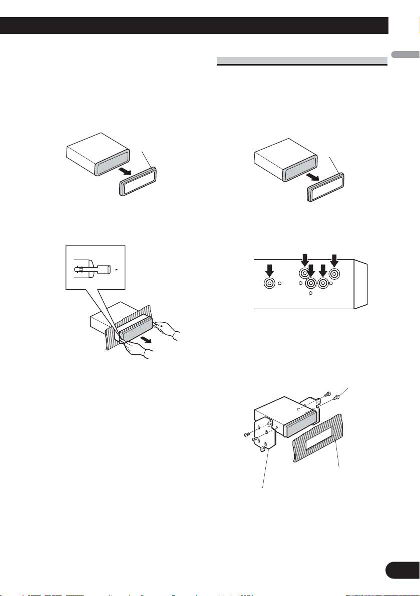
Removing the Unit
DIN Rear-mount
English
1. Extend top and bottom of the trim ring outwards
1. Extend top and bottom of the trim ring outwards
to remove the trim ring. When reattaching the
to remove the trim ring. When reattaching the
trim ring, push the trim ring onto the unit until it
trim ring, push the trim ring onto the unit until it
clicks. (If the trim ring is attached upside down,
clicks. (If the trim ring is attached upside down,
the trim ring will not fit properly.)
the trim ring will not fit properly.)
• It becomes easy to remove the trim ring if the
• It becomes easy to remove the trim ring if the
front panel is released.
front panel is released.
Español
Trim ring
Trim ring
Deutsch
2. Insert the supplied extraction keys into both sides
2. Determine the appropriate position where the
of the unit until they click into place.
holes on the bracket and the side of the unit
3. Pull the unit out of the dashboard.
match.
Français
3. Tighten two screws on each side.
• Use either truss screws (5 mm × 8 mm) or
flush surface screws (5 mm × 9 mm), depend-
Italiano
ing on the shape of screw holes in the
bracket.
Screw
Nederlands
Dashboard or Console
Factory radio mounting bracket
8
Table of contents
- Connecting the Units
- Connecting the Units
- Connecting the Units
- Installation
- Installation
- Conexión de las unidades
- Conexión de las unidades
- Conexión de las unidades
- Instalación
- Instalación
- Anschließen der Geräte
- Anschließen der Geräte
- Anschließen der Geräte
- Einbau
- Einbau
- Connexion des appareils
- Connexion des appareils
- Connexion des appareils
- Installation
- Installation
- Collegamento delle unità
- Collegamento delle unità
- Collegamento delle unità
- Installazione
- Installazione
- Aansluiten van de toestellen
- Aansluiten van de toestellen
- Aansluiten van de toestellen
- Installatie
- Installatie
- èÓ‰Íβ˜ÂÌË ÛÒÚÓÈÒÚ‚
- èÓ‰Íβ˜ÂÌË ÛÒÚÓÈÒÚ‚
- èÓ‰Íβ˜ÂÌË ÛÒÚÓÈÒÚ‚
- ìÒÚ‡Ìӂ͇
- ìÒÚ‡Ìӂ͇


