Pioneer HTP-SLH500: instruction
Class: Household, kitchen appliances, electronics and equipment
Type: Home Theater System
Manual for Pioneer HTP-SLH500
Table of contents
1
En
S-HV600B
S-HV500-LR
ඵᖑᏣقಜ
Subwoofer / Enceinte d’extrêmes graves / Subwoofer / Subwoofer /
S-SLW500
Subwoofer / Altavoz de subgraves / Subwoofer / Subwoofer /
Subwoofer / Subwoofer / Apubassokaiutin / Сабвуфер /
ົմඵᖑᏣ
ᐈձКь
cover_S-HV600B_S-HV500-LR.fm 1 ページ 2011年4月12日 火曜日 午後2時1分

S-HV600B_S-HV500-LR_En.fm 2 ページ 2011年4月12日 火曜日 午後2時31分
Thank you for buying this Pioneer product.
Please read through these operating instructions so you will know how to operate your model properly. After you have finished reading the
instructions, put them away in a safe place for future reference.
S-SLW500
• This product is a passive subwoofer, and must be combined
Before you start
with the VSX-S300 or other audio device provided with a built-
in subwoofer amplifier.
S-HV600B/S-HV500-LR
• This speaker system has an impedance of 4 Ω, and should be
• This speaker system has an impedance of 8 Ω, and should be
connected only to an amplifier designed with a load
connected only to an amplifier designed with a load
impedance of 4 Ω (the amplifier’s speaker output connector
impedance of 8 Ω (the amplifier’s speaker output connector
should clearly be labeled “4 Ω”).
should clearly be labeled “8 Ω”).
In order to prevent damage to the speaker system resulting
In order to prevent damage to the speaker system resulting
from input overload, please observe the following precautions:
from input overload, please observe the following precautions:
•Do not supply power to the speaker system in excess of the
•Do not supply power to the speaker system in excess of the
maximum permissible input.
maximum permissible input.
•When using a graphic equalizer to emphasize loud sounds in
•When using a graphic equalizer to emphasize loud sounds in
the high-frequency range, do not use excessive amplifier
the high-frequency range, do not use excessive amplifier
volume.
volume.
•Do not try to force a low-powered amplifier to produce loud
•Do not try to force a low-powered amplifier to produce loud
volumes of sound (the amplifier’s harmonic distortion will be
volumes of sound (the amplifier’s harmonic distortion will be
increased, and you may damage the speaker).
increased, and you may damage the speaker).
Caution: installation
Caution: installation
• Do not place the speaker on an unstable surface, as doing so
• Do not place the speaker on an unstable surface, as doing so
may cause the speaker to fall and cause damage or bodily
may cause the speaker to fall and cause damage or bodily
injury.
injury.
• Switch off and unplug your AV equipment and consult the
• Switch off and unplug your AV equipment and consult the
instructions when connecting up components. Make sure you
instructions when connecting up components. Make sure you
use the correct connecting cables.
use the correct connecting cables.
• Do not attach these speakers to the wall or ceiling, as they may
• If you intend to install the speakers on a wall, first confirm that
cause injury in the event of a fall.
the wall is capable of supporting the weight of the speaker
• Do not install your speakers overhead on the ceiling or wall.
systems (S-HV600B: 1.7 kg, S-HV500-LR: 0.4 kg). If you are
uncertain about the load-bearing capacity of the wall, consult
Caution: in use
a building specialist. Installing the speakers on an insecure
wall is extremely dangerous, since the speakers could fall,
• Do not use the speaker to output distorted sound for long
leading to grave personal injury.
periods of time. This can result in damages to the speaker and
poses a potential fire hazard.
• After mounting, confirm the safety of the installation. Make
periodic safety checks thereafter as well to confirm that the
• Do not place heavy or large objects on top of the speaker.
speakers continue to be mounted securely.
Doing so could provoke the speaker to fall, causing damages
or bodily injury.
Caution: in use
• Do not sit or stand on the speaker, or let children play on the
• Do not use the speaker to output distorted sound for long
speaker. Doing so could provoke the speaker to fall, causing
periods of time. This can result in damages to the speaker and
damages or bodily injury.
poses a potential fire hazard.
• The speaker system grill cannot be removed. Do not try to
• Do not place heavy or large objects on top of the speaker.
forcibly remove it since doing so may damage the grille.
Doing so could provoke the speaker to fall, causing damages
or bodily injury.
Pioneer is not responsible for any accidents or damage that
• Do not connect these speakers to devices other than an AV
amplifier or other audio component, since malfunctions could
result from improper installation, misuse or modification of
result.
the product, or natural disasters.
• This product incorporates autoregression technology to
protect the speakers. If the speakers stop emitting noise when
receiving too large a signal, turn the volume down on the amp
Cleaning the speaker cabinet
and wait a few seconds. The protection feature disables itself
With normal use, wiping with a dry cloth should be sufficient to
automatically.
keep the cabinet clean. If necessary, clean with a cloth dipped in
a neutral cleanser diluted five or six times with water, and wrung
out well. Do not use furniture wax or cleansers.
Never use thinners, benzine, insecticide sprays or other chemicals
on or near this unit since these will corrode the surfaces.
2
En
What’s in the box
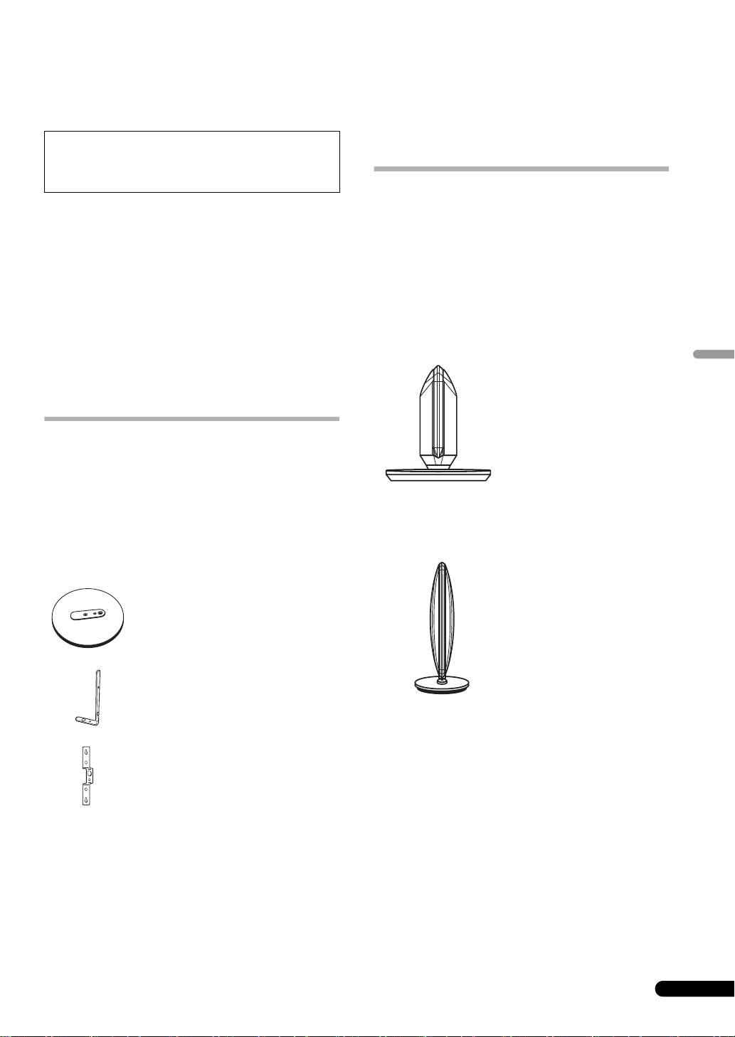
Features
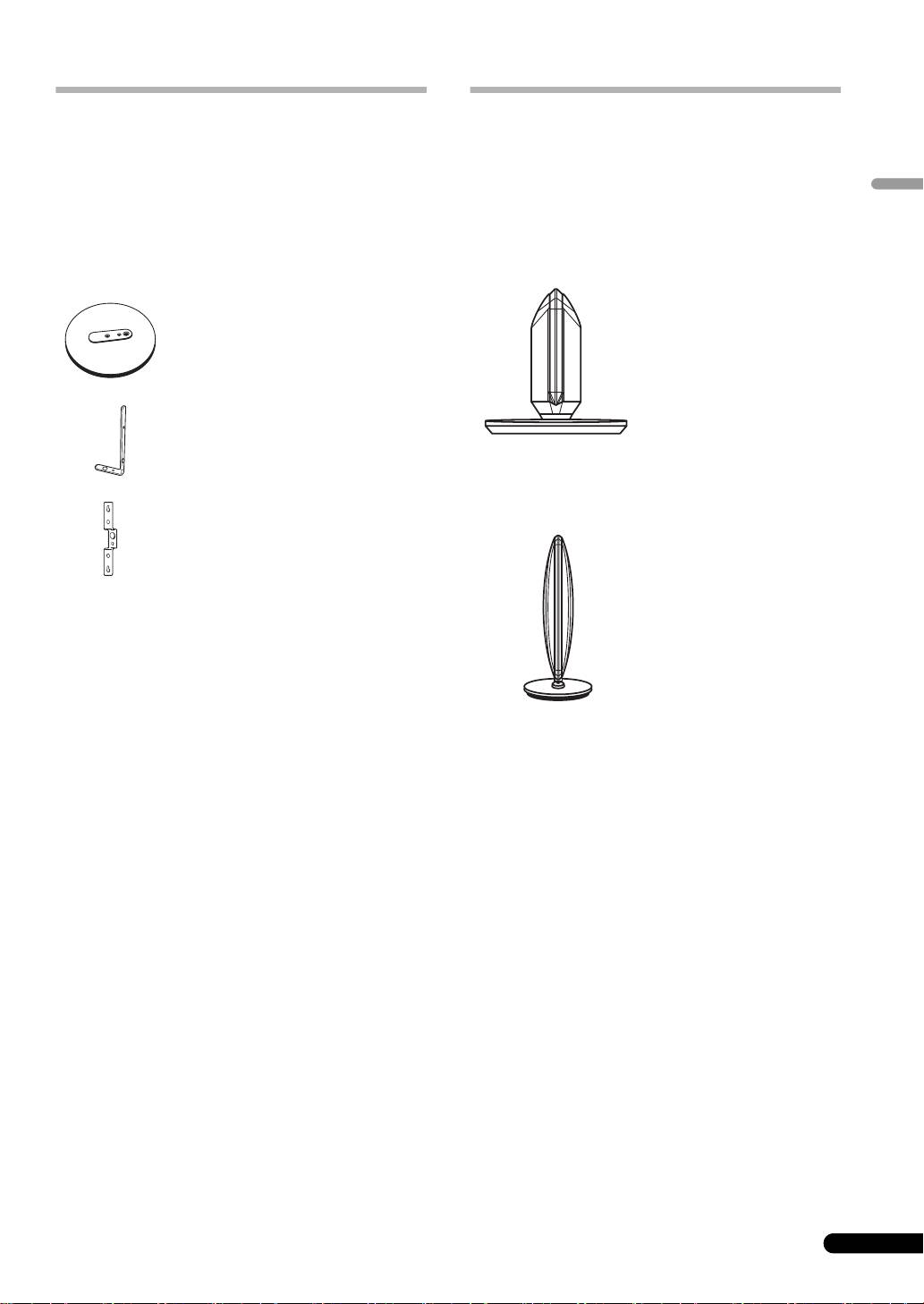
S-HV600B
• Sound is produced from both sides (grille net) of the speaker.
•Bracket x 2
• This speaker features full sound directed in every direction. In
• Non-skid pads x 2
contrast to ordinary speakers, the orientation shown below is
English
the “front.” To enjoy optimum sound quality, orient the speaker
•Wire stays x 4
so that this “front” side is pointed toward your listening
• Warranty card x 1 (European model only)
position.
• Operating instructions (this document)
S-HV500-LR: Horizontal orientation
S-HV500-LR
•Base x 2
‹Front appearance›
•Stand arm x 2
S-HV500-LR: Vertical orientation
•Bracket x 2
•Screw (Bind head) x 2
•Screw (Flat head) x 4
• Hexagonal nut x 2
•Seal x 2
• Warranty card x 1 (European model only)
• Operating instructions (this document)
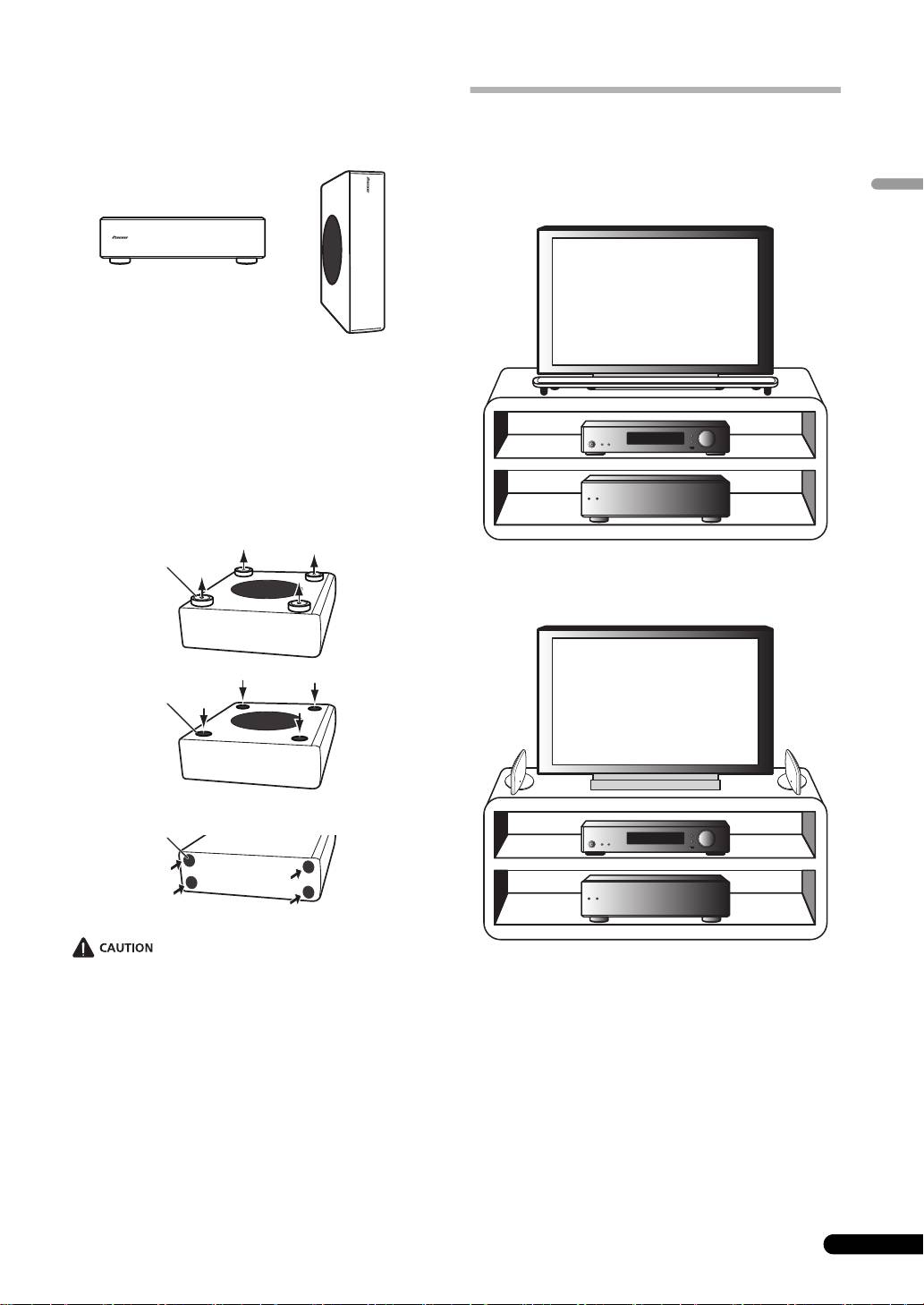
S-SLW500
• Speaker cord (3 m) x 1
• Non-skid pads x 4
•Seal x 4
• Warranty card x 1 (European model only)
3
En
‹Front appearance›
S-HV600B_S-HV500-LR_En.fm 3 ページ 2011年4月12日 火曜日 午後2時31分

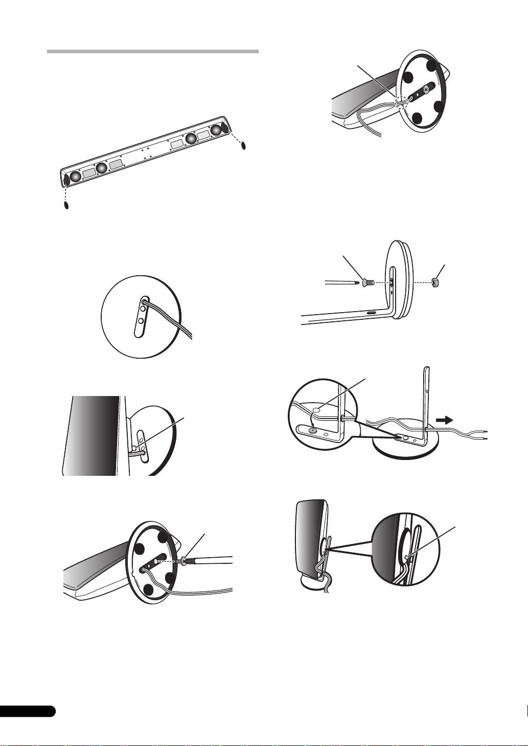
Vertical orientation
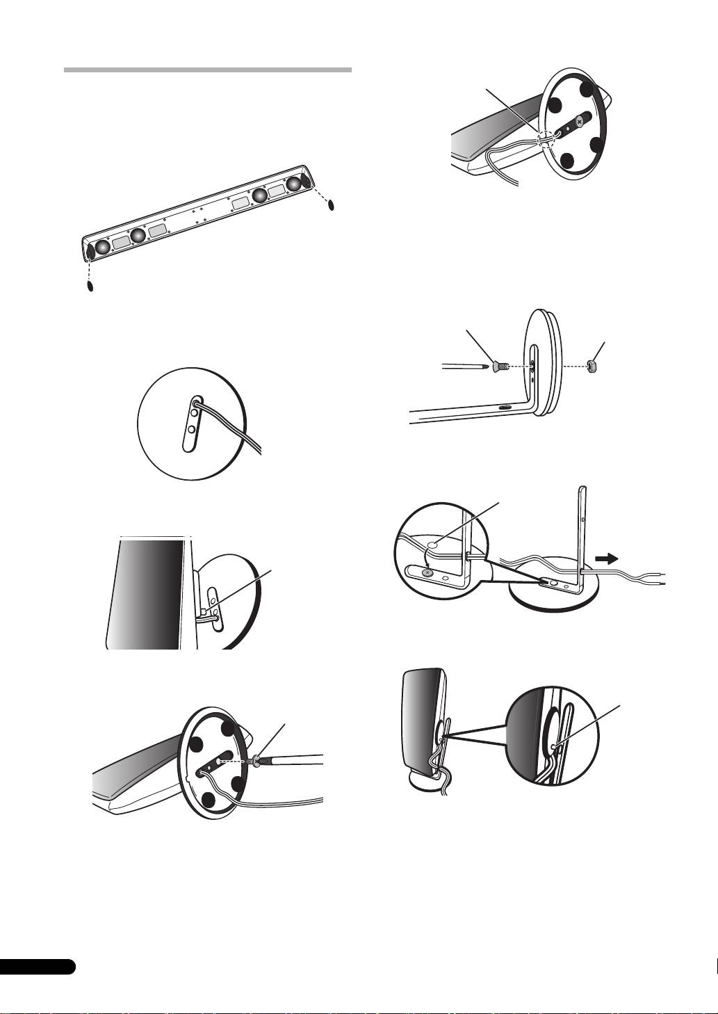
1 Align the vertical mounting stay with the hole in the
Assembly
base.
2 Fasten the vertical mount stay to the base using the
S-HV600B
vertical mount bolt and hex nut. Be sure the hex nut fits into
1 Apply the non-skid pad to the bottom surface of the leg.
the hexagonal groove in the bottom of the base.
S-HV500-LR
3 Pass the speaker cord through the vertical mount satay
Horizontal orientation
hole.
1 Pass the speaker cord through the hole in the base.
2 Align the rotation stop lug with the hole in the base.
4 Align the speaker's rotation stop lug with the hole in the
vertical stay.
3 Fasten the speaker to the base use the horizontal
mounting screw from the back side of the base.
5 Fasten the speaker to the vertical stay, using the vertical
mount screw.
4 Set the speaker so that the speaker cord passes through
the groove in the base.
4
En
Rotation
stop lug
Horizontal mount
screw
Wire cutout
Vertical mount screw
Vertical mount hex nut
Seal
Rotation
stop lug
Vertical mount screw
S-HV600B_S-HV500-LR_En.fm 4 ページ 2011年4月12日 火曜日 午後2時31分
S-SLW500
Installing the subwoofer
Installation
The subwoofer can be mounted in either vertical or horizontal ori-
entation. The factory default is horizontal orientation.
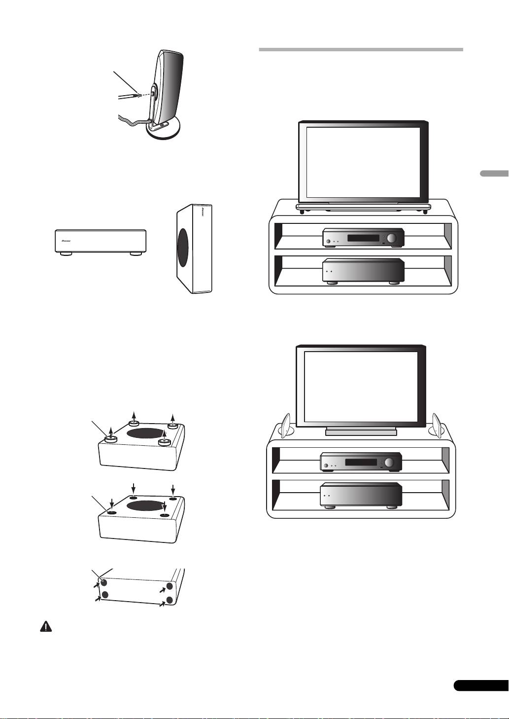
Mounting location
Installation example: For both S-HV600B and S-
SLW500
English
For vertical orientation installation
1 The feet are attached with Phillips screws; use a Phillips
screwdriver to remove them.
2 Apply the accessory seals to the place the feet were
located to hide the screw holes.
3 Apply the non-skid pads to the four corners of the surface
where the subwoofer is to be mounted. Note that the non-
skid pads may not be fully effective on all surfaces, so do not
install in slippery locations.
Installation example: For both S-HV500-LR and S-
SLW500
• Do not attempt to perform these procedures while tilting the
S-HV600B
unit at an angle. Lay the unit on its side on soft cloth or other
• Sounds played through speaker systems are easily affected in
material that will not scar the unit.
subtle ways by the conditions in the listening space.
• This speaker system does not feature a magnetically shielded
design. As a result, color distortion may occur if the speaker is
placed near a conventional CRT television. In this event, move
the speaker farther away from the television. In addition,
devices easily affected by magnetism (magnetic media cards,
wrist-watches, video tapes, etc.) should not be placed near
this speaker.
• If the room has a lot of reverberation, we recommend hanging
heavy fabric on the walls, and/or putting a carpet on the floor
to damp the sound. For best results, cover walls completely.
5
En
Step 1
Feet
Step 2
Seals
Step 3
Non-skid pads
S-HV600B_S-HV500-LR_En.fm 5 ページ 2011年4月12日 火曜日 午後2時31分
• When installing, allow at least 10 cm space between the rear
of the unit and any wall; when installing vertically, also allow
at least 10 cm space between the unit's left side and any wall.
• Mounting the speakers in an unstable location is extremely
If insufficient distance is taken, the unit may display
dangerous and should not be attempted.
inadequate performance, or may malfunction.
• Do not install the speakers on top of a television set or other
• Since the speaker system is heavy, installation in unstable
unstable location. The speakers may fall, causing damage or
locations is extremely dangerous and should not be
personal injury.
attempted. A falling speaker may cause damage or personal
S-HV500-LR
injury.
• Sounds played through speaker systems are easily affected in
subtle ways by the conditions in the listening space.
• Can be mounted vertically or horizontally.
Wall mounting the speakers
• When using a thin-profile television, place the speakers to the
(S-HV600B/S-HV500-LR)
sides of the television, separated from the television by 5 cm
or more.
• When using a CRT television, separate the speakers from the
Before mounting
television by 10 cm. Since these speakers are designed for
• Remember that the speaker system is heavy and that its
low-magnetic-flux leakage, some color smearing may be
weight could cause the screws to work loose, or the wall
experienced depending on the installation conditions. In this
material to fail to support it, resulting in the speaker falling.
case, turn off the power to the television and wait for 15
Make sure that the wall you intend to mount the speakers on
minutes to 30 minutes. If color smearing continues, separate
is strong enough to support them. Do not mount on plywood
the speaker systems farther from the television.
or soft surface walls.
• If the room has a lot of reverberation, we recommend hanging
• Mounting screws are not supplied. Use screws suitable for the
heavy fabric on the walls, and/or putting a carpet on the floor
wall material and support the weight of the speaker.
to damp the sound. For best results, cover walls completely.
• If you are unsure of the qualities and strength of the wall,
• Mounting the speakers in an unstable location is extremely
consult a professional for advice.
dangerous and should not be attempted.
• Pioneer is not responsible for any accidents or damage that
• Do not install the speakers on top of a television set or other
result from improper installation.
unstable location. The speakers may fall, causing damage or
S-HV600B
personal injury.
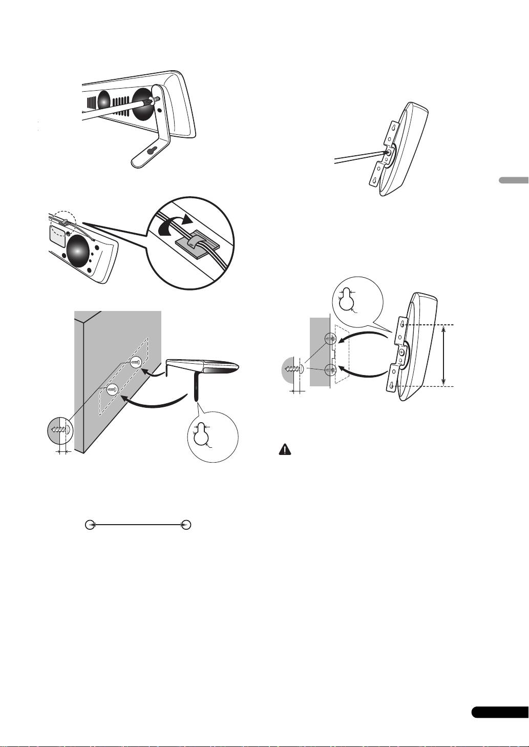
1 Use a Phillips screwdriver to remove the two screws
S-SLW500
holding the stands to the speaker.
• The subwoofer reproduces ultra-low sounds in monaural,
using the fact that the human ear has little directional
sensitivity to sounds in the low frequencies. As a result, the
subwoofer can be located in a variety of places, but if placed
too distant, the linkage between sounds of the subwoofer and
other speakers may seem unnatural. The intensity of the
sound from the subwoofer can be adjusted by changing the
distance from the wall.
• Front speakers installed to the right and left should be
separated by about 1.8 m to 2.7 m distance. They should be
2 Using the two screws removed in step 1, fasten the wall
installed at equal distances from the television, and at equal
mounting fixtures to the speaker.
heights from the floor.
• Optional speaker stands can be purchased to facilitate
optimal mounting of the surround speakers at or slightly
above the listener’s ear height.
• The surround effect will be diminished if the surround
speakers are mounted at extreme distances from the listener’s
position.
• The subwoofer is not magnetically shielded and so should not
be placed near a TV or monitor, as the interaction of magnetic
materials can cause distortion of the colors on your TV screen.
Devices easily affected by magnetism (magnetic media cards,
wrist-watches, video tapes, etc.) should not be placed near the
3 Affix the supplied wire stays to the top of the unit as
subwoofer.
shown and collect the cable there.
• When installing the speaker system on a TV rack or AV rack,
the rack or other audio components may vibrate due to
vibrations generated by the speaker. Caution should be taken
to assure that the rack shelves or other components do not
shift positions due to the vibration.
• Do not place disc media (DVD, CD) players on top of the
subwoofer since sound skipping may occur due to vibration.
6
En
Press until a “click”
is heard.
S-HV600B_S-HV500-LR_En.fm 6 ページ 2011年4月12日 火曜日 午後2時31分

4 Mount on wall.
• When mounting the unit on a wall, unit weight and mounting
methods may result in the danger of tipping or falling. Be very
careful to prevent accidents.
• During installation, take care to confirm that the location
chosen is fully able to support the weight of the unit. If you are
English
uncertain about the strength of the wall, consult a building
specialist.
• Pioneer takes no responsibility for damage or injury resulting
from faulty or improper installation, modification of the unit, or
natural disasters.
When mounting the unit on speaker stand
Use the accessory bracket when mounting the unit on any speak-
er stand or base other than those provided.
Use M5 screws for installation. Mounting screws are not provided.
Follow the instructions accompanying your selected speaker
stand or base.
Open two holes in the wall 818 mm apart.
S-HV500-LR
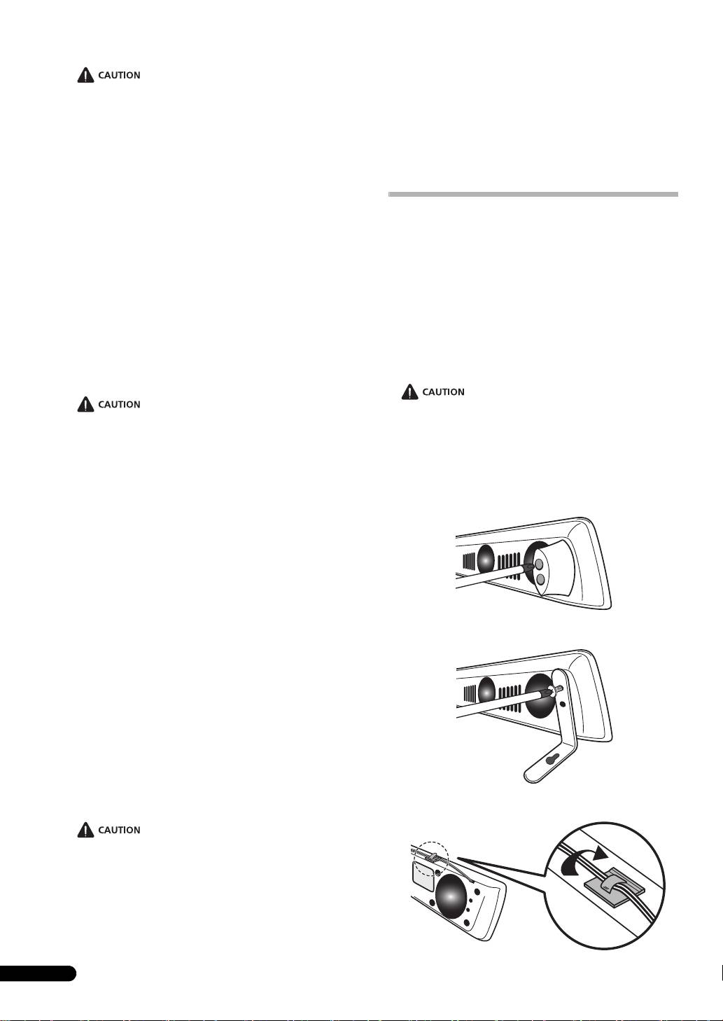
Wall mounting
To mount the unit on a wall, first use the vertical-installation screw
to fasten the wall-mount brackets to the unit, then fasten the
bracket to the wall.
Connection
Connecting the cord
S-HV600B/S-HV500-LR
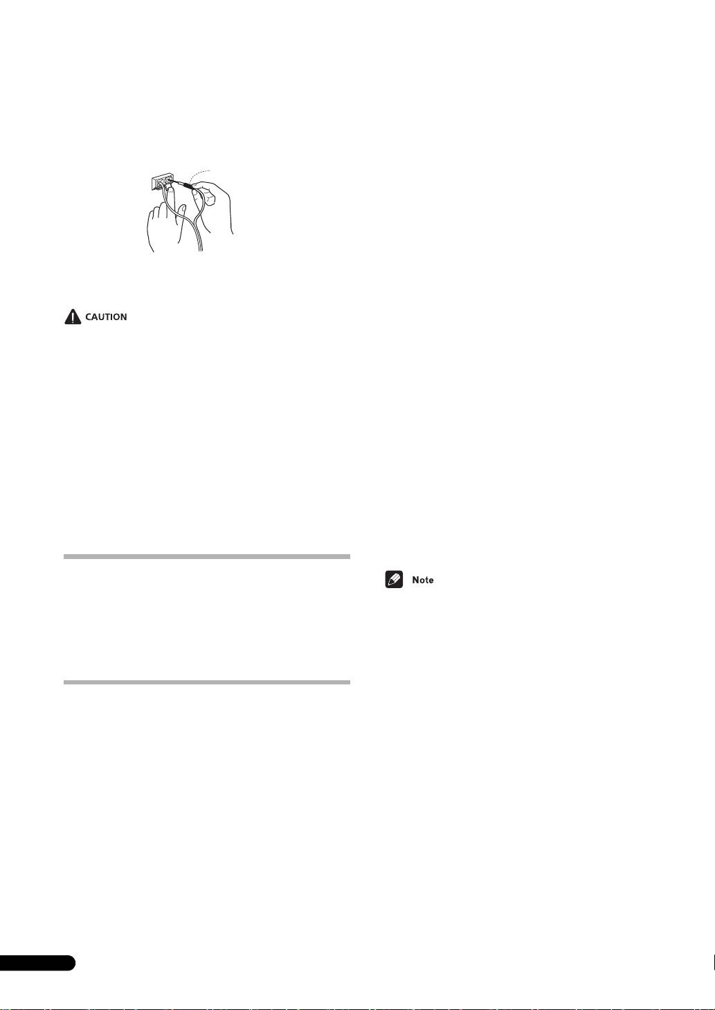
1 Switch off the power to your amplifier.
• Connect the wire with the colored marker to the red (+)
terminal; the plain wire to the black (–) terminal.
When mounting the unit on a wall, confirm that the wall construc-
tion is of a type that allows the mounting screws (available com-
mercially) to tighten fully and hold the speaker securely.
A wall made from weak material or of insufficient strength will be
unable to support the weight of the speaker, potentially resulting
in the speaker's falling.
Open two holes in the wall 95 mm apart.
2 Connect the other ends of the cords to the amp’s speaker
output terminals (for more details, refer to your amp
instruction manual).
7
En
Wall
mounting
screws
(available
commercially)*
5
mm
10
mm
6
mm
to 8
mm
* Wall mounting screws are not included. Purchase
appropriate screws taking into consideration the type
of wall and the weight of the speaker system.
818 mm
5
mm
10
mm
Wall mounting
screws
(available
commercially)*
95 mm
6
mm to
8
mm
* Wall mounting screws are not included. Purchase
appropriate screws taking into consideration the
type of wall and the weight of the speaker system.
60 mm
Red tube
T
S-HV600B_S-HV500-LR_En.fm 7 ページ 2011年4月12日 火曜日 午後2時31分
To plus
(+)
side (red)
o minus (–)
side (black)
S-HV600B_S-HV500-LR_En.fm 8 ページ 2011年4月15日 金曜日 午後7時27分
S-SLW500
S-HV500-LR
1 Attach one end of the supplied speaker cord to the rear
Enclosure . . . . . . . . . . . . . . . . . . . . . . . . . . . . . . . . . . . . . . . . Closed type
of the each speaker.
Configuration . . . . . . . . . . . . . . . . . . . . . . . . . . . . . . . . . . . . . . . . . . 2-way
• Connect the wire with the colored marker to the red (+)
Woofer/Tweeter
terminal; the plain wire to the black (–) terminal. Press down
. . . . . . . . . .5.7 cm x 3 cm (Double sided) x 2pcs / 2 cm Dome type x 2pcs
the spring-loaded tab and insert the wire, as shown below.
Impedance . . . . . . . . . . . . . . . . . . . . . . . . . . . . . . . . . . . . . . . . . . . . . .8 Ω
Release the tab to secure the wire.
Frequency range. . . . . . . . . . . . . . . . . . . . . . . . . . . . . . .170 Hz to 32 kHz
Sensitivity . . . . . . . . . . . . . . . . . . . . . . . . . . . . . . . . .76 dB (Total 82 dB*)
Red (+)
Maximum input power. . . . . . . . . . . . . . . . . . . . . . . . . . . . . . . . . . 100 W
Black (–)
Red colored marker
Crossover frequency. . . . . . . . . . . . . . . . . . . . . . . . . . . . . . . . . . . 1.5 kHz
Exterior dimensions
Horizontal orientation . . . 207 (W) mm x 100 (H) mm x 100 (D) mm
Vertical orientation. . . . . . 100 (W) mm x 225 (H) mm x 100 (D) mm
Weight . . . . . . . . . . . . . . . . . . . . . . . . . . . . . . . . . . . . . . . . . . . . . . . .0.4 kg
Supplied accessories
Base
. . . . . . . . . . . . . . . . . . . . . . . . . . . . . . . . . . . . . . . . . . . . . . . . . . . . .2
Stand arm . . . . . . . . . . . . . . . . . . . . . . . . . . . . . . . . . . . . . . . . . . . . . . . .2
2 Connect the other ends of the cords to the amp’s speaker
Bracket . . . . . . . . . . . . . . . . . . . . . . . . . . . . . . . . . . . . . . . . . . . . . . . . . . .2
output terminals (for more details, refer to your amp
Screw (Bind head) . . . . . . . . . . . . . . . . . . . . . . . . . . . . . . . . . . . . . . . . .2
instruction manual).
Screw (Flat head) . . . . . . . . . . . . . . . . . . . . . . . . . . . . . . . . . . . . . . . . . .4
Hexagonal nut. . . . . . . . . . . . . . . . . . . . . . . . . . . . . . . . . . . . . . . . . . . . .2
Seal . . . . . . . . . . . . . . . . . . . . . . . . . . . . . . . . . . . . . . . . . . . . . . . . . . . . . .2
Warranty card (European model only) . . . . . . . . . . . . . . . . . . . . . . . . . .1
• These speaker terminals carry HAZARDOUS LIVE voltage. To
Operating instructions (this document)
prevent the risk of electric shock when connecting or
disconnecting the speaker cords, disconnect the power cord
before touching any uninsulated parts.
S-SLW500
Enclosure . . . . . . . . . . . . . . . . . . . . . . . . . . . Bass-reflex bookshelf type
• After connecting the plugs, pull lightly on the cords to make
Configuration . . . . . . . . . . . . . . . . . . . . . . . . . . . . . . . . . . . . . 16 cm cone
sure that the ends of the cords are securely connected to the
Impedance . . . . . . . . . . . . . . . . . . . . . . . . . . . . . . . . . . . . . . . . . . . . . .4 Ω
terminals. Poor connections can create noise and
Frequency range. . . . . . . . . . . . . . . . . . . . . . . . . . . . . . . 35 Hz to 2.0 kHz
interruptions in the sound.
Sensitivity . . . . . . . . . . . . . . . . . . . . . . . . . . . . . . . . . . . . . . . . . . . . .78 dB
• If the cords’ wires happen to be pushed out of the terminals,
Maximum input power. . . . . . . . . . . . . . . . . . . . . . . . . . . . . . . . . . 100 W
allowing the wires to come into contact with each other, it
Exterior dimensions
places an excessive additional load on the receiver. This may
Horizontal orientation . . . 435 (W) mm x 121 (H) mm x 360 (D) mm
cause the amp to stop functioning, and may even damage the
Vertical orientation. . . . . 108.5 (W) mm x 435 (H) mm x 360 (D) mm
receiver.
Weight . . . . . . . . . . . . . . . . . . . . . . . . . . . . . . . . . . . . . . . . . . . . . . . .4.5 kg
• When using a set of speakers connected to an receiver, you
Supplied accessories
won’t be able to obtain the normal stereo effect if the polarity
Speaker cord (3 m). . . . . . . . . . . . . . . . . . . . . . . . . . . . . . . . . . . . . . . . . .1
(+, –) of one of the speakers (left or right) is reversed.
Non-skid pads. . . . . . . . . . . . . . . . . . . . . . . . . . . . . . . . . . . . . . . . . . . . . .4
Seal . . . . . . . . . . . . . . . . . . . . . . . . . . . . . . . . . . . . . . . . . . . . . . . . . . . . . .4
Warranty card (European model only) . . . . . . . . . . . . . . . . . . . . . . . . . .1
Operation (S-HV600B/S-HV500-LR)
• The S-HV500-LR is shipped with two speaker systems per
Since the S-HV600B/S-HV500-LR are designed as compact
package.
satellite speakers, it is recommended that they be used in
combination with a sub-woofer to provide full base sound. In this
• Specifications and design subject to possible modification
case, set your amplifier (receiver) speaker setting to “small” and
without notice, due to improvements.
the crossover frequency to 200 Hz.
* Since these speakers produce sound from both sides, the output
is doubled. Sound volume is equivalent to 82 dB with ordinary
speakers.
Specifications
© 2011 PIONEER CORPORATION.
All rights reserved.
S-HV600B
Enclosure . . . . . . . . . . . . . . . . . . . . . . . . . . . . . . . . . . . . . . . .Closed type
Configuration . . . . . . . . . . . . . . . . . . . . . . . . . . . . . . . . . . . . . . . . . .2-Way
Woofer/Tweeter
. . . . . . . . . .5.7 cm x 3 cm (Double sided) x 4pcs / 2 cm Dome type x 4pcs
Impedance . . . . . . . . . . . . . . . . . . . . . . . . . . . . . . . . . . . . . . . . . . . . . .8 Ω
Frequency range. . . . . . . . . . . . . . . . . . . . . . . . . . . . . . .130 Hz to 32 kHz
Sensitivity . . . . . . . . . . . . . . . . . . . . . . . . . . . . . . . . 76 dB (Total 82 dB*)
Maximum input power. . . . . . . . . . . . . . . . . . . . . . . . . . . . . . . . . . 100 W
Crossover frequency. . . . . . . . . . . . . . . . . . . . . . . . . . . . . . . . . . . 1.5 kHz
Exterior dimensions . . . . . . . . . 900 (W) mm x 66 (H) mm x 93 (D) mm
Weight . . . . . . . . . . . . . . . . . . . . . . . . . . . . . . . . . . . . . . . . . . . . . . . .1.7 kg
Supplied accessories
Bracket . . . . . . . . . . . . . . . . . . . . . . . . . . . . . . . . . . . . . . . . . . . . . . . . . . .2
Non-skid pads . . . . . . . . . . . . . . . . . . . . . . . . . . . . . . . . . . . . . . . . . . . . . .2
Wire stays . . . . . . . . . . . . . . . . . . . . . . . . . . . . . . . . . . . . . . . . . . . . . . . . .4
Warranty card (European model only) . . . . . . . . . . . . . . . . . . . . . . . . . .1
Operating instructions (this document)
8
En
For European model
English
9
En
If you want to dispose this product, do not mix it with general household waste. There is a separate collection system for used
electronic products in accordance with legislation that requires proper treatment, recovery and recycling.
Private households in the member states of the EU, in Switzerland and Norway may return their used electronic products free of charge to
designated collection facilities or to a retailer (if you purchase a similar new one).
For countries not mentioned above, please contact your local authorities for the correct method of disposal.
By doing so you will ensure that your disposed product undergoes the necessary treatment, recovery and recycling and thus prevent potential
negative effects on the environment and human health.
K058b_A1_En
S-HV600B_S-HV500-LR_En.fm 9 ページ 2011年4月12日 火曜日 午後2時31分

S-HV600B_S-HV500-LR_En.fm 2 ページ 2011年4月12日 火曜日 午後3時45分
Nous vous remercions d’avoir acheté ce produit Pioneer.
Veuillez lire attentivement ce mode d’emploi de manière à pouvoir utiliser votre modèle correctement. Après avoir lu ces explications,
conservez-les en lieu sûr pour éventuellement les consulter plus tard.
S-SLW500
• Cet appareil est une enceinte d’extrêmes graves passive et il
Avant de commencer
doit être combiné avec le VSX-S300 ou un autre dispositif
audio, incorporant un amplificateur d’enceinte d’extrêmes
S-HV600B/S-HV500-LR
graves.
• Cette enceinte acoustique a une impédance de 8 Ω et elle doit
• Cette enceinte acoustique a une impédance de 4 Ω et elle doit
être raccordée uniquement à un amplificateur conçu pour
être raccordée uniquement à un amplificateur conçu pour
une impédance de charge de 8 Ω (le connecteur de sortie
une impédance de charge de 4 Ω (le connecteur de sortie
haut-parleur de l’amplificateur doit porter clairement
haut-parleur de l’amplificateur doit porter clairement
l’identification pour “8 Ω”).
l’identification pour “4 Ω”).
Pour éviter d’endommager les enceintes par une surcharge à
Pour éviter d’endommager les enceintes par une surcharge à
l’entrée, observez les précautions suivantes :
l’entrée, observez les précautions suivantes :
•Ne fournissez pas aux enceintes acoustiques une puissance
•Ne fournissez pas aux enceintes acoustiques une puissance
électrique dépassant l’entrée maximale autorisée.
électrique dépassant l’entrée maximale autorisée.
•Si vous utilisez un égaliseur graphique pour accentuer les
•Si vous utilisez un égaliseur graphique pour accentuer les
sons dans la plage des hautes fréquences, n’élevez pas trop
sons dans la plage des hautes fréquences, n’élevez pas trop
le volume de l’amplificateur.
le volume de l’amplificateur.
•N’essayez pas de pousser un amplificateur de faible
•N’essayez pas de pousser un amplificateur de faible
puissance à produire un volume sonore élevé, car la
puissance à produire un volume sonore élevé, car la
distorsion harmonique de l’amplificateur en serait
distorsion harmonique de l’amplificateur en serait
accentuée et vous pourriez endommager les haut-parleurs.
accentuée et vous pourriez endommager les haut-parleurs.
Précautions: Installation
Précautions: Installation
• Ne placez pas l’enceinte sur une surface instable, car elle
• Ne placez pas l’enceinte sur une surface instable, car elle
pourrait tomber et provoquer ainsi des blessures corporelles
pourrait tomber et provoquer ainsi des blessures corporelles
ou des dégâts.
ou des dégâts.
• Mettez votre système audiovisuel hors tension et débranchez-
• Mettez votre système audiovisuel hors tension et débranchez-
le, puis consultez le mode d’emploi avant de brancher des
le, puis consultez le mode d’emploi avant de brancher des
composants. Prenez soin d’utiliser correctement les câbles de
composants. Prenez soin d’utiliser correctement les câbles de
raccordement.
raccordement.
• Si vous souhaitez installer les enceintes sur une paroi, vérifiez
• N’attachez pas ces enceintes sur un mur ou au plafond car, en
d’abord que celle-ci est capable de supporter le poids des
tombant, elles pourraient causer des blessures.
enceintes (S-HV600B : 1,7 kg, S-HV500-LR : 0.4 kg). Si vous
• N’installez pas les enceintes en hauteur, au plafond ou sur
avez des doutes au sujet de la capacité de résistance de la
une paroi.
paroi, consultez un spécialiste de ce secteur. Installer les
enceintes sur une paroi non appropriée est extrêmement
Précautions: d’utilisation
dangereux car, en tombant, elles pourraient provoquer de
sérieuses blessures.
• N’utilisez pas l’enceinte pour produire des sons distordus
pendant une longue période. Ceci pourrait endommager le
• Après le montage, confirmez la sécurité de l’installation. Par
haut-parleur et même provoquer un incendie.
la suite, effectuez des vérifications de sécurité périodiques
pour confirmer que les enceintes restent fermement montées.
• Ne posez pas d’objets lourds ou volumineux sur le dessus des
enceintes. Ce faisant, l’enceinte pourrait tomber et provoquer
Précautions: d’utilisation
des blessures ou des dégâts.
• N’utilisez pas l’enceinte pour produire des sons distordus
• Ne montez pas et ne vous asseyez pas sur les enceintes et ne
pendant une longue période. Ceci pourrait endommager le
laissez pas des enfants jouer sur celles-ci. Ce faisant,
haut-parleur et même provoquer un incendie.
l’enceinte pourrait tomber et provoquer des blessures ou des
dégâts.
• Ne posez pas d’objets lourds ou volumineux sur le dessus des
enceintes. Ce faisant, l’enceinte pourrait tomber et provoquer
• La grille des enceintes ne peut pas être enlevée. N’essayez pas
des blessures ou des dégâts.
de la retirer de force car elle pourrait en être endommagée.
• Ne connectez pas ces enceintes à des dispositifs autres qu’un
amplificateur AV ou un autre composant audio, car des
Pioneer n’assume aucune responsabilité en cas d’accidents ou
dysfonctionnements pourraient en résulter.
de dégâts, résultant d’une installation inappropriée, d’une
• Cet appareil incorpore une technologie d’autorégression afin
erreur d’utilisation, d’une altération du produit ou de
de protéger les haut-parleurs. Si les haut-parleurs cessent
catastrophes naturelles.
d’émettre des sons à la réception d’un signal trop puissant,
réduisez le volume sur l’amplificateur et attendez quelques
secondes. Cette fonction de protection se désactive
automatiquement.
Nettoyage du coffret de l’enceinte
Normalement, il suffira de frotter le coffret de ces enceintes avec
un linge sec pour maintenir leur propreté. Au besoin, trempez un
linge dans un détergent neutre allongé de cinq à six fois son
volume d’eau et essorez bien le linge avant de l’utiliser pour frotter
le coffret. N’utilisez pas de cire ou de détergent pour mobilier.
2
Fr

N’employez jamais de diluant, benzine, insecticide en atomiseur
ou autre produit chimique sur les coffrets ou à proximité, car cela
Caractéristiques
endommagerait leurs surfaces.
• Le son est produit par les deux côtés (écran grille) de
l’enceinte.
Contenu de l’emballage
• Cette enceinte dirige des sons complets vers chaque
direction. A la différence des enceintes ordinaires,
l’orientation illustrée ci-dessous est “l’avant”. Pour bénéficier
S-HV600B
d’une qualité sonore optimale, orientez l’enceinte de telle
•Applique x 2
manière que le côté “avant” soit dirigé vers votre position
• Coussinets antidérapants x 2
d’écoute.
•Etai à fil x 4
• Carte de garantie x 1 (modèle européen seulement)
S-HV500-LR: Orientation horizontale
• Mode d’emploi (ce document)
Français
S-HV500-LR
•Base x 2
S-HV500-LR: Orientation verticale
• Bras de socle x 2
•Applique x 2
• Vis (à tête intégrée) x 2
• Vis (à tête plate) x 4
• Ecrou hexagonal x 2
•Joint x 2
• Carte de garantie x 1 (modèle européen seulement)
• Mode d’emploi (ce document)
S-SLW500
• Cordon d’enceinte (3 m) x 1
• Coussinets antidérapants x 4
•Joint x 4
• Carte de garantie x 1 (modèle européen seulement)
3
Fr
‹Aspect avant›
S-HV600B_S-HV500-LR_En.fm 3 ページ 2011年4月12日 火曜日 午後3時45分
‹Aspect avant›
Assemblage
S-HV600B
1 Fixez les coussinets antidérapants sur la surface
inférieure de la patte.
Orientation verticale
1 Alignez l’étai de montage vertical avec le trou dans la
base.
2 Fixez l’étai de montage vertical sur la base au moyen du
boulon de montage vertical et de l’écrou hexagonal. Assurez-
vous que l’écrou hexagonal s’emboîte bien dans l’encoche
hexagonale sur le fond de la base.
S-HV500-LR
Orientation horizontale
1 Passez le cordon de haut-parleur par le trou dans la base.
3 Passez le cordon de haut-parleur par le trou de l’étai de
montage vertical.
2 Alignez l’ergot d’arrêt de rotation avec le trou dans la
base.
4 Alignez l’ergot d’arrêt de rotation avec le trou dans l’étai
vertical.
3 Fixez le haut-parleur sur la base au moyen de la vis de
montage horizontal par le côté arrière de la base.
5 Fixez le haut-parleur sur l’étai vertical au moyen de la vis
de montage vertical.
4 Ajustez le haut-parleur de sorte que son cordon passe par
l’encoche prévue dans la base.
4
Fr
Ergot d´arrêt de
rotation
Vis de montage
horizontal
Coupure de fil
Vis de montage vertical
Ecrou hexagonal de
montage vertical
Joint
Ergot d´arrêt
de rotation
S-HV600B_S-HV500-LR_En.fm 4 ページ 2011年4月12日 火曜日 午後3時45分
Installation
Emplacement de montage
Exemple d’installation : Pour les S-HV600B et S-
SLW500
S-SLW500
Installation de l’enceinte d’extrêmes graves
L’enceinte d’extrêmes graves peut être montée en position
Français
verticale ou horizontale. La position par défaut est l’orientation
horizontale.
Pour une installation en position verticale
1 Les pieds sont attachés avec des vis cruciformes. Utilisez
Exemple d’installation : Pour les S-HV500-LR et S-
un tournevis à pointe cruciforme pour les déposer.
SLW500
2 Appliquez les joints fournis comme accessoires à l’endroit
ou se trouvaient les pieds pour cacher les trous des vis.
3 Fixez les coussinets antidérapants aux quatre coins de la
surface où l’enceinte d’extrêmes graves doit être montée.
Sachez que les coussinets antidérapants ne seront pas
efficaces sur toutes les surfaces ; ne les installez donc pas à
des endroits glissants.
S-HV600B
• Les sons reproduits par les enceintes acoustiques sont
facilement affectés de manière subtile par les conditions du
local d’écoute.
• Cette enceinte acoustique ne présente pas un design à
blindage magnétique. Par conséquent, une distorsion des
couleurs peut se produire si l’enceinte est disposée près d’un
téléviseur à écran cathodique ordinaire. Dans ce cas, écartez
davantage l’enceinte par rapport au téléviseur. De plus, ne
placez pas près de cette enceinte des objets (cartes
magnétiques, montres-bracelets, bandes vidéo, etc.)
facilement affectés par le magnétisme.
• N’essayez pas d’effectuer ces démarches en inclinant
l’appareil. Déposez-le sur son flanc sur un linge ou un autre
matériau qui ne le griffera pas.
5
Fr
Vis de montage vertical
Etape 1
Pieds
Etape 2
Joints
Etape 3
Coussinets antidérapants
S-HV600B_S-HV500-LR_En.fm 5 ページ 2011年4月12日 火曜日 午後3時45分
ATTENTION

• Si la pièce à tendance à réverbérer les sons, nous conseillons
de suspendre des tentures aux murs et/ou de placer un tapis
sur le plancher afin d’amortir les sons. Pour obtenir les
• Si les enceintes acoustiques sont installées dans un rack de
meilleurs résultats possibles, couvrez complètement les
télévision ou un rack audiovisuel, celui-ci et les autres
murs.
composants audio pourraient vibrer par suite des vibrations
produites par les haut-parleurs. On veillera à ce que les
étagères, racks et autres composants ne bougent pas par
suite des vibrations.
• Installer les enceintes dans un endroit instable est
• Ne placez pas des lecteurs de disques (DVD, CD) sur le dessus
extrêmement dangereux. N’essayez pas de le faire.
de l’enceinte d’extrêmes graves car des interruptions des sons
• N’installez pas les enceintes sur le dessus d’un téléviseur ou
pourraient se produire du fait des vibrations.
dans un autre endroit instable. Elles pourraient tomber et
• Lors de l’installation, laissez un espace d’au moins 10 cm
causer des blessures ou des dégâts.
entre l’arrière de l’appareil et toute paroi. Lors d’une
S-HV500-LR
installation verticale, laissez un espace d’au moins 10 cm
• Les sons reproduits par les enceintes acoustiques sont
entre la face gauche et toute paroi. Si une distance suffisante
facilement affectés de manière subtile par les conditions du
n’est pas prise, les performances de l’appareil seront
local d’écoute.
inadéquates ou il pourrait mal fonctionner.
• Montage vertical ou horizontal impossible.
• Comme l’enceinte acoustique est pesante, son installation
dans un endroit instable est extrêmement dangereuse. La
• Si vous utilisez un téléviseur à écran plat, placez les enceintes
chute d’une enceinte pourrait causer des blessures ou des
sur les côtés du téléviseur en les séparant d’au moins 5 cm.
dégâts.
• Si vous utilisez un téléviseur à écran cathodique, écartez les
enceintes et cette télévision de 10 cm. Comme ces enceintes
sont conçues pour réduire les pertes de flux magnétique, un
certain maculage des couleurs peut être observé selon les
Fixation des enceintes sur une paroi
conditions de l’installation. Dans ce cas, coupez
l’alimentation au téléviseur et attendez pendant 15 à 30
(S-HV600B/S-HV500-LR)
minutes. Si le maculage des couleurs subsiste, écartez
davantage les enceintes et le téléviseur.
• Si la pièce à tendance à réverbérer les sons, nous conseillons
Avant l’installation
de suspendre des tentures aux murs et/ou de placer un tapis
• Souvenez-vous que l’enceinte est pesante et que son poids
sur le plancher afin d’amortir les sons. Pour obtenir les
peut faire se décrocher les vis ou arracher le matériau de la
meilleurs résultats possibles, couvrez complètement les
paroi, provoquant la chute de l’enceinte. Assurez-vous que la
murs.
paroi sur laquelle vous voulez monter les enceintes est assez
solide pour les supporter. N’installez pas les enceintes sur des
parois en contreplaqué ou sur une surface friable.
• Les vis de fixation ne sont pas fournies. Utilisez des vis
• Installer les enceintes dans un endroit instable est
appropriées en fonction du matériau de la paroi et soutenez
extrêmement dangereux. N’essayez pas de le faire.
l’enceinte pendant son installation.
• N’installez pas les enceintes sur le dessus d’un téléviseur ou
dans un autre endroit instable. Elles pourraient tomber et
causer des blessures ou des dégâts.
• Si vous hésitez quant aux qualités et à la résistance de la paroi,
S-SLW500
demandez conseil à un professionnel.
• L’enceinte d’extrêmes graves reproduit des sons ultra graves
• Pioneer n’est pas responsable en cas d’accident ou de dégâts
en monaural, tirant parti de la faible sensitivité directionnelle
résultant d'une installation inadéquate.
de l’oreille humaine aux basses fréquences. Par conséquent,
le caisson peut être placé en divers endroits, mais s’il est trop
S-HV600B
éloigné, la liaison entre les sons du caisson et des autres haut-
1 Utilisez un tournevis à tête cruciforme pour déposer les
parleurs risque de sembler peu naturelle. L’intensité du son de
deux vis fixant les supports sur l’enceinte.
l’enceinte d’extrêmes graves peut être ajustée en modifiant la
distance par rapport au mur.
• Les haut-parleurs avant installés sur la droite et la gauche doit
être séparés d’environ 1,8 m à 2,7 m. Ils doivent être installés
à une distance égale du téléviseur et à une hauteur égale par
rapport au plancher.
• Des supports d’enceinte peuvent être achetés en option pour
permettre un placement optimal des haut-parleurs surround
au niveau des oreilles de l’auditeur ou légèrement au-dessus.
• L’effet surround sera atténué si les haut-parleurs surround
sont montés très loin de la position de l’auditeur.
• L’enceinte d’extrêmes graves n’est pas blindé
magnétiquement; par conséquent, on ne la placera pas près
d’un téléviseur ou d’un moniteur, car l’interaction des
matériaux magnétiques peut provoquer une distorsion des
couleurs sur l’écran du téléviseur. Des dispositifs facilement
affectés par le magnétisme (cartes magnétiques, montres,
bandes vidéo, etc.) ne devraient pas être placés près de
l’enceinte d’extrêmes graves.
6
Fr
ATTENTION
ATTENTION
S-HV600B_S-HV500-LR_En.fm 6 ページ 2011年4月12日 火曜日 午後3時45分
ATTENTION
ATTENTION
2 Servez-vous des deux vis déposées à l’étape 1 pour fixer
S-HV500-LR
les appliques de montage sur l’enceinte.
Fixation sur une paroi
Pour fixer l’appareil sur une paroi, servez-vous d’abord de la vis
d’installation verticale pour immobiliser les appliques de montage
sur paroi, puis fixez l’applique sur la paroi.
3 Fixez les étais de fil fournis sur le dessus de l’appareil
comme illustré et immobilisez le câble à cet endroit.
Français
Lors d’un montage de l’appareil sur une paroi, assurez-vous que
la construction de celle-ci est d’un type permettant aux vis de
fixation (disponibles dans le commerce) d’y pénétrer à fond et de
maintenir l’enceinte fermement.
Une paroi fabriquée en un matériau friable ou d’une résistance
insuffisante ne parviendra pas à supporter le poids de l’enceinte,
ce qui pourrait entraîner sa chute.
Forez deux trous distants de 95 mm dans le mur.
4 Fixation sur une paroi.
• Si l’appareil est installé sur une paroi, son poids et la méthode
de montage peuvent présenter un danger de chute. Soyez très
prudent pour éviter tout accident.
• Avant l’installation, assurez-vous que l’endroit choisi sera
Forez deux trous distants de 818 mm dans le mur.
parfaitement capable de supporter le poids de l’appareil. Si
vous avez des doutes au sujet de la résistance de la paroi,
consultez un spécialiste de ce secteur.
• Pioneer n’assume pas de responsabilité en cas de dégâts ou
de blessures résultant d’une installarion erronée ou
inadéquate, une modification de l’appareil ou de catastrophes
naturelles.
7
Fr
Appuyer jusqu´à entendre un “déclic”.
Vis de montage
sur paroi
(disponibles
dans le
commerce)
*
5
mm
10
mm
6 mm à 8 mm
*
Les vis de montage sur paroi ne sont pas fournies.
Procurez-vous des vis appropriées en tenant compte du
type de paroi et du poids des enceintes.
S-HV600B_S-HV500-LR_En.fm 7 ページ 2011年4月12日 火曜日 午後3時45分
5
mm
10
mm
Vis de montage
sur paroi
(disponibles
dans le
commerce)
*
95
mm
6 mm à 8 mm
*
Les vis de montage sur paroi ne sont pas fournies.
Procurez-vous des vis appropriées en tenant compte du
type de paroi et du poids des enceintes.
ATTENTION
818 mm

Lors du montage de l’appareil sur le socle
2 Raccordez l’autre bout des cordons sur les bornes de
sortie d’enceinte de l’amplificateur (pour plus
d’enceinte
d’informations, consultez le mode d’emploi de votre
Utilisez l’applique fournie si vous voulez monter l’appareil sur un
amplificateur).
support ou une base d’enceinte autre que celles qui sont fournies.
Utilisez des vis M5 pour l’installation. Les vis de fixation ne sont
pas fournies. Suivez les instructions fournies avec le support ou le
socle d'enceinte que vous avez choisi.
• Ces bornes d’enceintes sont sous une tension
OPÉRATIONNELLE DANGEREUSE. Pour prévenir tout risque
de secousse électrique lors du branchement ou du
débranchement des cordons d’enceinte, débranchez le
cordon d’alimentation avant de toucher des parties non
isolées.
• Après avoir branché les fiches, tirez légèrement sur celles-ci
pour vous assurer que leur extrémité est parfaitement
immobilisée par les bornes. De mauvaises connexions sont la
source de parasites, voire d’interruptions des sons.
• Si les fils des cordons devaient ressortir des bornes et si ces
fils entraient mutuellement en contact, le récepteur subirait
une forte charge supplémentaire. Ceci pourrait provoquer une
interruption de l’amplificateur, voire endommager le
récepteur.
• A l’emploi d’un jeu d’enceintes raccordé à un récepteur, si la
polarité (+, –) d’une des enceintes acoustiques (gauche ou
Connexions
droite) est inversée, vous n’obtiendrez pas un effet
stéréophonique normal.
Connexion du cordon
S-HV600B/S-HV500-LR
1 Mettez l’amplificateur hors tension.
Fonctionnement
• Connectez le fil à repère coloré sur la borne rouge (+) et
l’autre fil sur la borne noire (–).
(S-HV600B/S-HV500-LR)
Comme les S-HV600B/S-HV500-LR sont conçus comme enceintes
satellites compactes, il est recommandé de les utiliser en
combinaison avec une enceinte d’extrêmes graves pour
bénéficier d’excellents sons graves. Dans ce cas, ajustez le
réglage d’enceinte de l’amplificateur (récepteur) sur “faible” et la
fréquence de recouvrement sur 200 Hz.
2 Raccordez l’autre bout des cordons sur les bornes de
sortie d’enceinte de l’amplificateur (pour plus
d’informations, consultez le mode d’emploi de votre
amplificateur).
S-SLW500
1 Fixez une extrémité du cordon de haut-parleur fourni sur
l’arrière de chaque haut-parleur.
• Connectez le fil à repère coloré sur la borne rouge (+) et
l’autre fil sur la borne noire (–). Enfoncez l’onglet à ressort et
insérez le fil comme illustré ci-dessous. Relâchez l’onglet pour
immobiliser le fil.
8
Fr
60 mm
Au côté plus
(+)
(rouge)
Tube rouge
Au côté moins
(–)
(noir)
Rouge (+)
Marqueur de couleur rouge
Noir (–)
S-HV600B_S-HV500-LR_En.fm 8 ページ 2011年4月12日 火曜日 午後3時45分
ATTENTION

S-SLW500
Coffret . . . . . . . . . . . . . . . . . . . . . . . . . . Type bibliothèque, basse reflex
Fiche technique
Configuration . . . . . . . . . . . . . . . . . . . . . . . . . . . . . . . . . .Cône de 16 cm
Impédance. . . . . . . . . . . . . . . . . . . . . . . . . . . . . . . . . . . . . . . . . . . . . . 4 Ω
S-HV600B
Plage de fréquence. . . . . . . . . . . . . . . . . . . . . . . . . . . . . 35 Hz à 2,0 kHz
Coffret . . . . . . . . . . . . . . . . . . . . . . . . . . . . . . . . . . . . . . . . . . . Type fermé
Sensibilité . . . . . . . . . . . . . . . . . . . . . . . . . . . . . . . . . . . . . . . . . . . . .78 dB
Configuration . . . . . . . . . . . . . . . . . . . . . . . . . . . . . . . . . . . . . . . . .2 voies
Puissance d’entrée maximum. . . . . . . . . . . . . . . . . . . . . . . . . . . . 100 W
Woofer/Tweeter
Dimensions extérieures
. . . . . . 5,7 cm x 3 cm (Double côté) x 4pcs / 2 cm Type à dôme x 4pcs
Orientation horizontale . . . 435 (L) mm x 121 (H) mm x 360 (P) mm
Impédance. . . . . . . . . . . . . . . . . . . . . . . . . . . . . . . . . . . . . . . . . . . . . . 8 Ω
Orientation verticale. . . . . 108,5 (L) mm x 435 (H) mm x 360 (P) mm
Plage de fréquence. . . . . . . . . . . . . . . . . . . . . . . . . . . . . 130 Hz à 32 kHz
Poids . . . . . . . . . . . . . . . . . . . . . . . . . . . . . . . . . . . . . . . . . . . . . . . . 4,5 kg
Sensibilité . . . . . . . . . . . . . . . . . . . . . . . . . . . . . . . . 76 dB (Total 82 dB*)
Accessoires fournis
Puissance d’entrée maximum. . . . . . . . . . . . . . . . . . . . . . . . . . . . 100 W
Cordon d’enceinte (3 m) . . . . . . . . . . . . . . . . . . . . . . . . . . . . . . . . . . . . 1
Fréquence de recouvrement . . . . . . . . . . . . . . . . . . . . . . . . . . . . 1,5 kHz
Coussinets antidérapants . . . . . . . . . . . . . . . . . . . . . . . . . . . . . . . . . . . 4
Dimensions extérieures . . . . . . . 900 (L) mm x 66 (H) mm x 93 (P) mm
Joint . . . . . . . . . . . . . . . . . . . . . . . . . . . . . . . . . . . . . . . . . . . . . . . . . . . . . 4
Poids . . . . . . . . . . . . . . . . . . . . . . . . . . . . . . . . . . . . . . . . . . . . . . . . 1,7 kg
Carte de garantie (modèle européen seulement) . . . . . . . . . . . . . . . . 1
Français
Accessoires fournis
Applique. . . . . . . . . . . . . . . . . . . . . . . . . . . . . . . . . . . . . . . . . . . . . . . . . . 2
Remarque
Coussinets antidérapants . . . . . . . . . . . . . . . . . . . . . . . . . . . . . . . . . . . 2
Etai à fil . . . . . . . . . . . . . . . . . . . . . . . . . . . . . . . . . . . . . . . . . . . . . . . . . . 4
• Le S-HV500-LR est livré avec deux enceintes par ensemble.
Carte de garantie (modèle européen seulement) . . . . . . . . . . . . . . . . 1
• Spécifications et design sous réserve de modifications sans
Mode d’emploi (ce document)
préavis en raison d’améliorations éventuelles.
S-HV500-LR
* Comme ces enceintes produisent des sons par les deux côtes,
Coffret . . . . . . . . . . . . . . . . . . . . . . . . . . . . . . . . . . . . . . . . . . . Type fermé
la sortie en est doublée. Le volume sonore est équivalent à 82 dB
Configuration . . . . . . . . . . . . . . . . . . . . . . . . . . . . . . . . . . . . . . . . .2 voies
avec des enceintes ordinaires.
Woofer/Tweeter
. . . . . . . . 5,7 cm x 3 cm (Double côté) x 2pcs / 2 cm Dome type x 2pcs
Impédance. . . . . . . . . . . . . . . . . . . . . . . . . . . . . . . . . . . . . . . . . . . . . . 8 Ω
© 2011 PIONEER CORPORATION.
Plage de fréquence. . . . . . . . . . . . . . . . . . . . . . . . . . . . . 170 Hz à 32 kHz
Tous droits de reproduction et de traduction réservés.
Sensibilité . . . . . . . . . . . . . . . . . . . . . . . . . . . . . . . . 76 dB (Total 82 dB*)
Puissance d’entrée maximum. . . . . . . . . . . . . . . . . . . . . . . . . . . . 100 W
Fréquence de recouvrement . . . . . . . . . . . . . . . . . . . . . . . . . . . . 1,5 kHz
Dimensions extérieures
Orientation horizontale . . . 207 (L) mm x 100 (H) mm x 100 (P) mm
Orientation verticale . . . . . . 100 (L) mm x 225 (H) mm x 100 (P) mm
Poids . . . . . . . . . . . . . . . . . . . . . . . . . . . . . . . . . . . . . . . . . . . . . . . . 0,4 kg
Accessoires fournis
Base
. . . . . . . . . . . . . . . . . . . . . . . . . . . . . . . . . . . . . . . . . . . . . . . . . . . . . 2
Bras de socle. . . . . . . . . . . . . . . . . . . . . . . . . . . . . . . . . . . . . . . . . . . . . 2
Applique . . . . . . . . . . . . . . . . . . . . . . . . . . . . . . . . . . . . . . . . . . . . . . . . . 2
Vis (à tête intégrée). . . . . . . . . . . . . . . . . . . . . . . . . . . . . . . . . . . . . . . . 2
Vis (à tête plate). . . . . . . . . . . . . . . . . . . . . . . . . . . . . . . . . . . . . . . . . . . 4
Ecrou hexagonal . . . . . . . . . . . . . . . . . . . . . . . . . . . . . . . . . . . . . . . . . . 2
Joint . . . . . . . . . . . . . . . . . . . . . . . . . . . . . . . . . . . . . . . . . . . . . . . . . . . . . 2
Carte de garantie (modèle européen seulement) . . . . . . . . . . . . . . . . 1
Mode d’emploi (ce document)
Pour le modèle européen
9
Fr
Si vous souhaitez vous débarrasser de cet appareil, ne le mettez pas à la poubelle avec vos ordures ménagères. Il existe un système de
collecte séparé pour les appareils électroniques usagés, qui doivent être récupérés, traités et recyclés conformément à la législation.
Les habitants des états membres de l’UE, de Suisse et de Norvège peuvent retourner gratuitement leurs appareils électroniques usagés aux
centres de collecte agréés ou à un détaillant (si vous rachetez un appareil similaire neuf).
Dans les pays qui ne sont pas mentionnés ci-dessus, veuillez contacter les autorités locales pour savoir comment vous pouvez vous débarrasser
de vos appareils.
Vous garantirez ainsi que les appareils dont vous vous débarrassez sont correctement récupérés, traités et recyclés et préviendrez de cette façon
les impacts néfastes possibles sur l’environnement et la santé humaine.
K058b_A1_Fr
S-HV600B_S-HV500-LR_En.fm 9 ページ 2011年4月15日 金曜日 午後7時34分

S-HV600B_S-HV500-LR_En.fm 2 ページ 2011年4月12日 火曜日 午後4時9分
Wir danken Ihnen dafür, dass Sie sich für dieses Produkt von Pioneer entschieden haben.
Bitte lesen Sie diese Bedienungsanleitung vor der Inbetriebnahme aufmerksam durch, damit Sie die optimale Leistung von diesem Produkt
erzielen können. Bitte bewahren Sie diese Anleitung anschließend für spätere Bezugnahme griffbereit auf.
• Dieses Produkt enthält eine Autoregressions-Technologie
zum Schutz der Lautsprecher. Falls ein Signal mit zu hohem
Vor der Inbetriebnahme
Pegel zugeleitet wird, so dass die Lautsprecher keinen Ton
mehr abgeben, verringern Sie die Lautstärke am Verstärker,
S-HV600B/S-HV500-LR
und warten Sie dann einige Sekunden, bis die Tonausgabe
• Dieses Lautsprechersystem besitzt eine Nennimpedanz von
fortgesetzt wird. Die Schutzfunktion wird automatisch
8 Ω und darf daher ausschließlich an einen Verstärker mit
deaktiviert.
einer Lastimpedanz von 8 Ω angeschlossen werden (die
Lautsprecherklemmen des Verstärkers müssen mit der
S-SLW500
Beschriftung „8 Ω“ gekennzeichnet sein).
• Bei diesem Produkt handelt es sich um einen passiven
Um eine Beschädigung des Lautsprechersystems durch ein
Subwoofer, der mit dem Modell VSX-S300 oder einem anderen
zu starkes Eingangssignal zu vermeiden, sind die folgenden
Audiogerät kombiniert werden muss, dass über einen
Vorsichtshinweise sorgfältig zu beachten:
eingebauten Subwoofer-Verstärker verfügt.
•Die zulässige Belastbarkeit (Eingangspegel) dieses
• Dieses Lautsprechersystem besitzt eine Nennimpedanz von
Lautsprechersystems darf auf keinen Fall überschritten
4 Ω und darf daher ausschließlich an einen Verstärker mit
werden.
einer Lastimpedanz von 4 Ω angeschlossen werden (die
•Wenn ein Grafik-Equalizer verwendet wird, um den hohen
Lautsprecherklemmen des Verstärkers müssen mit der
Frequenzbereich anzuheben, darf die Lautstärke am
Beschriftung „4 Ω“ gekennzeichnet sein).
Verstärker nicht auf einen übermäßig hohen Pegel
Um eine Beschädigung des Lautsprechersystems durch ein
eingestellt werden.
zu starkes Eingangssignal zu vermeiden, sind die folgenden
•Versuchen Sie auf keinen Fall, einen sehr hohen
Vorsichtshinweise sorgfältig zu beachten:
Lautstärkepegel von einem Verstärker mit niedriger
•Die zulässige Belastbarkeit (Eingangspegel) dieses
Ausgangsleistung zu erzielen (dies führt zu einer Erhöhung
Lautsprechersystems darf auf keinen Fall überschritten
des Klirrfaktors des Verstärkers und kann eine
werden.
Beschädigung des Lautsprechers verursachen).
•Wenn ein Grafik-Equalizer verwendet wird, um den hohen
Frequenzbereich anzuheben, darf die Lautstärke am
Vorsichtshinweise zur Aufstellung
Verstärker nicht auf einen übermäßig hohen Pegel
• Stellen Sie den Lautsprecher auf einer stabilen Unterlage auf.
eingestellt werden.
Anderenfalls besteht die Gefahr, dass der Lautsprecher
•Versuchen Sie auf keinen Fall, einen sehr hohen
umkippt und Verletzungen oder eine Beschädigung
Lautstärkepegel von einem Verstärker mit niedriger
verursacht.
Ausgangsleistung zu erzielen (dies führt zu einer Erhöhung
• Schalten Sie die AV-Anlage aus, und ziehen Sie alle
des Klirrfaktors des Verstärkers und kann eine
Netzstecker ab, bevor Sie die Anschlüsse unter Bezugnahme
Beschädigung des Lautsprechers verursachen).
auf die Bedienungsanleitungen der einzelnen Komponenten
herstellen. Achten Sie unbedingt darauf, die richtigen
Vorsichtshinweise zur Aufstellung
Anschlusskabel zu verwenden.
• Stellen Sie den Lautsprecher auf einer stabilen Unterlage auf.
• Vergewissern Sie sich vor einer Montage der Lautsprecher an
Anderenfalls besteht die Gefahr, dass der Lautsprecher
einer Wand, dass das Tragvermögen der Wand für das
umkippt und Verletzungen oder eine Beschädigung
Gewicht der Lautsprechersysteme ausreicht (S-HV600B: 1,7
verursacht.
kg, S-HV500-LR: 0,4 kg). Falls Sie das Tragvermögen der Wand
• Schalten Sie die AV-Anlage aus, und ziehen Sie alle
nicht selbst ermitteln können, ziehen Sie bitte einen
Netzstecker ab, bevor Sie die Anschlüsse unter Bezugnahme
Fachmann zu Rate. Eine Montage der Lautsprecher an einer
auf die Bedienungsanleitungen der einzelnen Komponenten
Wand, deren Tragvermögen nicht ausreicht, ist äußerst
herstellen. Achten Sie unbedingt darauf, die richtigen
gefährlich, da die Lautsprecher herunterfallen und schwere
Anschlusskabel zu verwenden.
Verletzungen verursachen können.
• Dieser Lautsprecher darf auf keinen Fall an einer Wand oder
• Vergewissern Sie sich nach der Montage, dass die
der Decke montiert werden, da er anderenfalls herunterfallen
Lautsprecher sicher befestigt sind. Führen Sie auch danach in
und Verletzungen verursachen kann.
regelmäßigen Abständen eine Sicherheitsprüfung aus, um zu
• Dieser Lautsprecher darf nicht oberhalb des Kopfniveaus an
gewährleisten, dass die Lautsprecher weiterhin sicher
der Decke oder an einer Wand befestigt werden.
montiert sind.
Vorsichtshinweise zum Betrieb
Vorsichtshinweise zum Betrieb
• Verwenden Sie den Lautsprecher auf keinen Fall zur
• Verwenden Sie den Lautsprecher auf keinen Fall zur
Wiedergabe von verzerrtem Klang über längere Zeiträume
Wiedergabe von verzerrtem Klang über längere Zeiträume
hinweg. Anderenfalls kann der Lautsprecher beschädigt
hinweg. Anderenfalls kann der Lautsprecher beschädigt
werden, und es besteht die Gefahr eines Brandausbruchs.
werden, und es besteht die Gefahr eines Brandausbruchs.
• Stellen Sie keine schweren oder großen Gegenstände auf den
• Stellen Sie keine schweren oder großen Gegenstände auf den
Lautsprecher. Anderenfalls besteht die Gefahr, dass der
Lautsprecher. Anderenfalls besteht die Gefahr, dass der
Lautsprecher umkippt und Verletzungen oder eine
Lautsprecher umkippt und Verletzungen oder eine
Beschädigung verursacht.
Beschädigung verursacht.
• Bitte sorgen Sie dafür, dass sich Personen nicht auf den
• Schließen Sie diese Lautsprecher ausschließlich an einen AV-
Lautsprecher setzen oder sich darauf stellen, und dass Kinder
Verstärker oder eine andere Audiokomponente an, da
nicht auf dem Lautsprecher spielen. Anderenfalls besteht die
anderenfalls Funktionsstörungen auftreten können.
Gefahr, dass der Lautsprecher umkippt und Verletzungen oder
eine Beschädigung verursacht.
2
De
• Die Frontverkleidung dieses Lautsprechers kann nicht
S-SLW500
abgenommen werden. Bitte versuchen Sie auf keinen Fall, die
• Lautsprecherkabel (3 m) x 1
Frontverkleidung gewaltsam zu entfernen, da sie dadurch
• Rutschfestes Kissen x 4
beschädigt werden kann.
• Aufkleber x 4
• Garantiekarte x 1 (nur Modell für Europa)
Pioneer übernimmt keinerlei Haftung für Unfälle oder
Schäden, die durch eine unsachgemäße Aufstellung,
zweckentfremdeten Gebrauch bzw. Nachgestaltung des
Produkts oder höhere Gewalt entstehen.
Merkmale
• Ton wird von beiden Seiten (Frontverkleidung) des
Reinigen des Lautsprechergehäuses
Lautsprechers abgegeben.
Unter normalen Bedingungen lassen sich Staub, Fingerabdrücke
• Bei diesem Lautsprecher erfolgt die Schallabstrahlung in
und leichte Verschmutzungen durch Abreiben des
allen Richtungen. Im Gegensatz zu herkömmlichen
Lautsprechergehäuses mit einem trockenen Tuch entfernen. Falls
hartnäckige Schmutzflecken an den Außenflächen vorhanden
Lautsprechern handelt es sich bei der in der nachstehenden
sind, tauchen Sie einen sauberen Lappen in eine Lösung aus 5 bis
Abbildung gezeigten Ausrichtung um die „Vorderseite“ des
6 Teilen eines neutralen Haushaltsreinigers und 1 Teil Wasser,
Lautsprechers. Um die optimale Klangqualität zu erhalten,
wringen Sie ihn gründlich aus, und wischen Sie die
stellen Sie den Lautsprecher so auf, dass diese „Vorderseite“
Schmutzflecken dann ab. Benutzen Sie dazu keine
auf die Hörposition weist.
Möbelpolituren oder -reinigungsmittel.
Verwenden Sie auf keinen Fall Farbverdünner, Leichtbenzin,
S-HV500-LR: Horizontale Ausrichtung
Insektizide oder andere Chemikalien zur Reinigung des Gehäuses
Deutsch
oder in der Nähe dieses Lautsprechers, da derartige Mittel das
Oberflächenfinish anlösen.
Mitgeliefertes Zubehör
S-HV600B
• Halterung x 2
• Rutschfestes Kissen x 2
‹Ansicht von vorn›
• Kabelschelle x 4
• Garantiekarte x 1 (nur Modell für Europa)
• Bedienungsanleitung (dieses Dokument)
S-HV500-LR: Vertikale Ausrichtung
S-HV500-LR
• Grundplatte x 2
•Ständerarm x 2
• Halterung x 2
• Schraube (Linsenkopf) x 2
• Schraube (Flachkopf) x 4
• Sechskantmutter x 2
• Aufkleber x 2
• Garantiekarte x 1 (nur Modell für Europa)
• Bedienungsanleitung (dieses Dokument)
3
De
‹Ansicht von vorn›
S-HV600B_S-HV500-LR_En.fm 3 ページ 2011年4月12日 火曜日 午後4時9分
Zusammenbau
S-HV600B
1 Bringen Sie das rutschfeste Kissen an der Unterseite des
Beins an.
Vertikale Ausrichtung
1 Richten Sie die vertikale Montagestrebe auf das Loch in
der Grundplatte aus.
2 Befestigen Sie die vertikale Montagestrebe mit der
Schraube für vertikale Befestigung und der Sechskantmutter
an der Grundplatte. Achten Sie dabei darauf, die
Sechskantmutter in die sechseckige Nut in der Unterseite der
Grundplatte einzupassen.
S-HV500-LR
Horizontale Ausrichtung
1 Führen Sie das Lautsprecherkabel durch das Loch in der
Grundplatte.
3 Führen Sie das Lautsprecherkabel durch das Loch in der
vertikalen Befestigungsstrebe.
2 Richten Sie die Drehverhinderungsnase auf das Loch in
der Grundplatte aus.
4 Richten Sie die Drehverhinderungsnase des
Lautsprechers auf das Loch in der vertikalen Strebe aus.
3 Befestigen Sie den Lautsprecher an der Grundplatte,
indem Sie die Schraube für horizontale Befestigung von der
Rückseite der Grundplatte her einsetzen.
5 Befestigen Sie den Lautsprecher mit der Schraube für
vertikale Befestigung an der vertikalen Strebe.
4 Richten Sie den Lautsprecher so aus, dass das
Lautsprecherkabel durch die Nut in der Grundplatte verlegt
werden kann.
4
De
Drehverhinderungsnase
Schraube für
horizontale Befestigung
Aussparung für Kabel
Schraube für
vertikale Befestigung
Sechskantmutter für
vertikale Befestigun
Aufkleber
S-HV600B_S-HV500-LR_En.fm 4 ページ 2011年4月12日 火曜日 午後4時9分
Drehver-
hinderungsnase
