Pioneer PDA-V100HD: instruction
Class: Household, kitchen appliances, electronics and equipment
Type: Home Theater System
Manual for Pioneer PDA-V100HD
Table of contents
- IMPORTANT
- VENTILATION CAUTION STANDBY/ON Button Operating Environment
- Contents
- Chapter 1 Important user information
- Chapter 2 Safety precautions
- Chapter 3 Features Supported Plasma Televisions
- Chapter 4 Supplied accessories
- Chapter 5 Part names
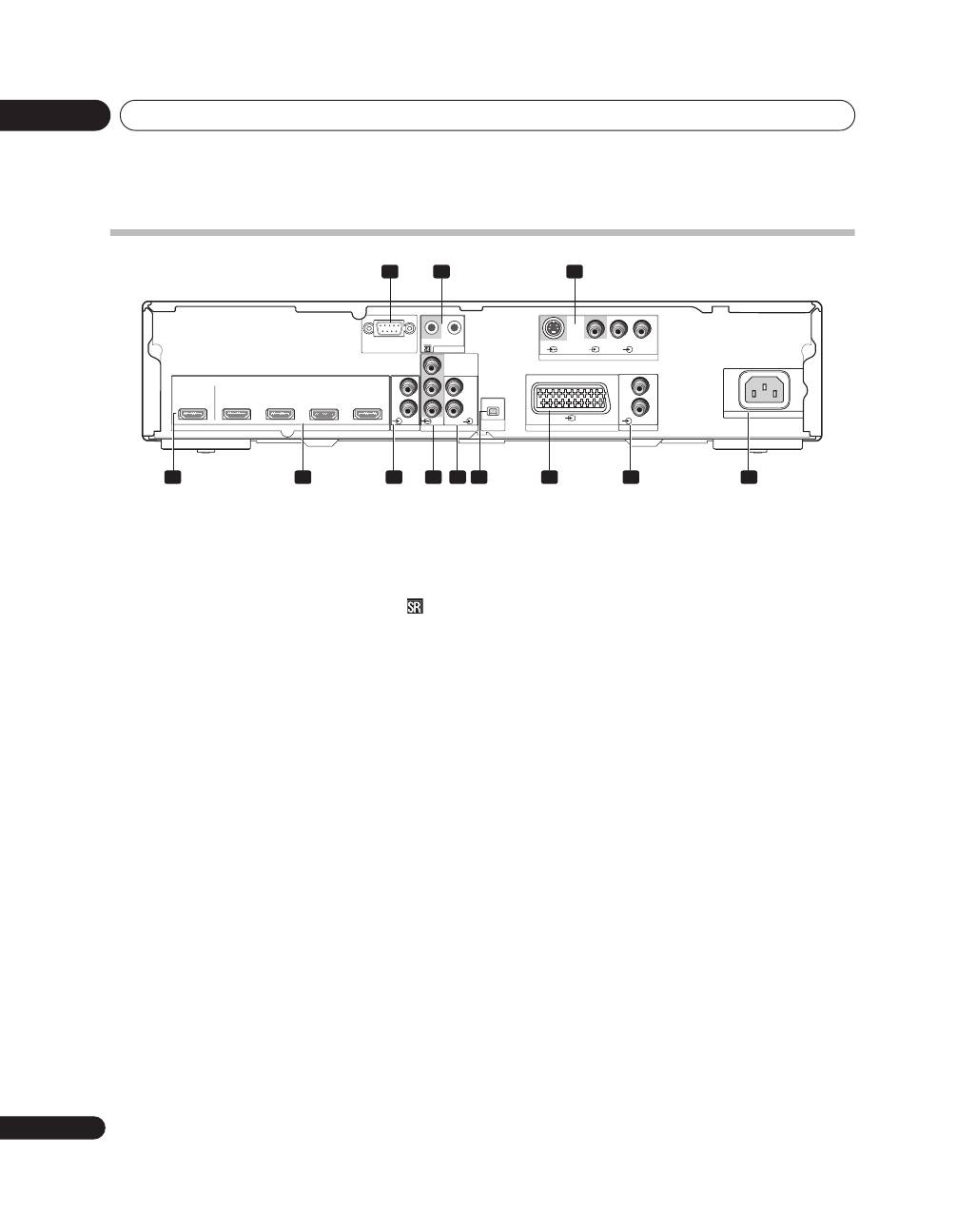
- Rear
- Remote control unit
- Chapter 6 Preparation Installing the unit Preparing the remote control unit
- Operating range of the remote control unit
- Chapter 7 Using the unit Operation modes Operations/Operation restrictions HDMI Control setting
- Connecting the unit to a Pioneer plasma television (see Chapter 8)
- Chapter 8 Using the unit with a Pioneer plasma television
- Chapter 9 Using the unit with other televisions
- Chapter 10 Advanced functions Connecting control cables
- Changing settings Changing HDMI output resolution Selecting the colour system Selecting the INPUT3 source signal Item Description
- Setting the video signal format Setting the audio signal when using HDMI input
- Chapter 11 Using with other components Connections to a television Connections to input components
- Using the HDMI input Connections to a HDMI- supported component About HDMI
- Connections to a component equipped with SCART connector Connections to a component with component connectors
- Chapter 12 Additional information Troubleshooting Problem Possible solution
- Problem Possible solution
- SCART pin assignments
- Specifications
- Operation of the unit’s indicators During normal operation PDP combination mode Independent 1 mode
- Independent 2 mode During setting mode When setting HDMI output resolution (when RESOLUTION button is pressed.) When setting colour system for analog signals (when COLOUR SYSTEM button is pressed.)
- When selecting INPUT 3 source signal (when SIGNAL SELECT button is pressed.) When setting HDMI video signal format (when VIDEO button is pressed.) When setting HDMI audio signal format (when AUDIO button is pressed.) Unsupported settings (when a remote control unit button not supported by currently selected input is pressed.)

The exclamation point within an equilateral
triangle is intended to alert the user to the
presence of important operating and
maintenance (servicing) instructions in the
literature accompanying the appliance.
The lightning flash with arrowhead symbol,
within an equilateral triangle, is intended to
alert the user to the presence of uninsulated
"dangerous voltage" within the product's
enclosure that may be of sufficient
magnitude to constitute a risk of electric
shock to persons.
CAUTION:
TO PREVENT THE RISK OF ELECTRIC
SHOCK, DO NOT REMOVE COVER (OR
BACK). NO USER-SERVICEABLE PARTS
INSIDE. REFER SERVICING TO QUALIFIED
SERVICE PERSONNEL.
CAUTION
RISK OF ELECTRIC SHOCK
DO NOT OPEN
IMPORTANT
D3-4-2-1-1_En-A
Replacement and mounting of an AC plug on the power supply cord of this unit should be performed only by qualified
service personnel.
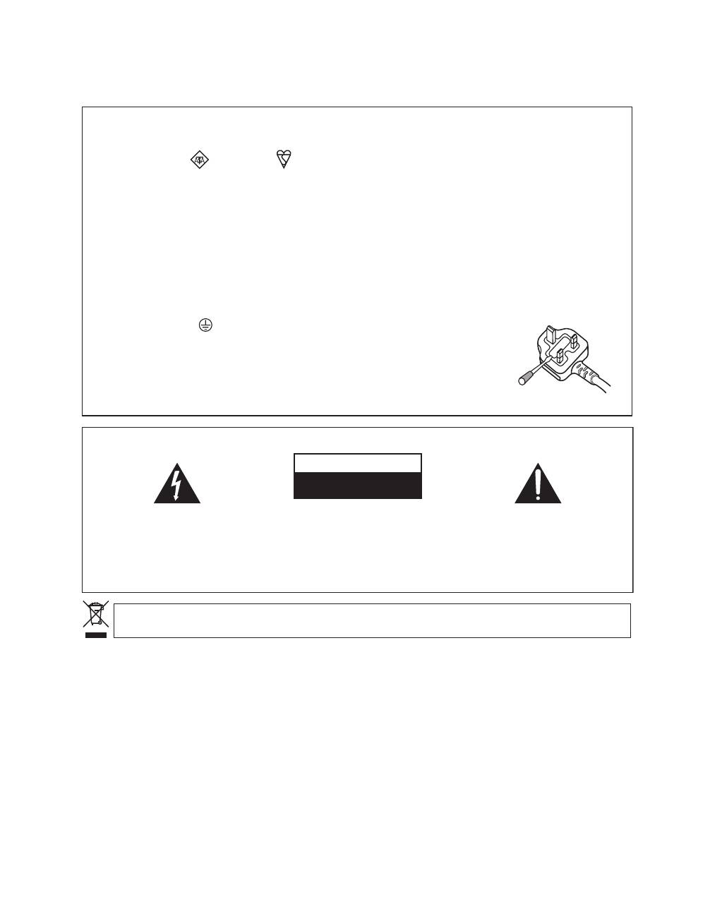
IMPORTANT: THE MOULDED PLUG
This appliance is supplied with a moulded three pin mains plug for your safety and convenience. A 13 amp fuse is fitted in this plug. Should the
fuse need to be replaced, please ensure that the replacement fuse has a rating of 13 amps and that it is approved by ASTA or BSI to BS1362.
Check for the ASTA mark
or the BSI mark
on the body of the fuse.
If the plug contains a removable fuse cover, you must ensure that it is refitted when the fuse is replaced. If you lose the fuse cover the plug
must not be used until a replacement cover is obtained. A replacement fuse cover can be obtained from your local dealer.
If the fitted moulded plug is unsuitable for your socket outlet, then the fuse shall be removed and the plug cut off and disposed of
safely. There is a danger of severe electrical shock if the cut off plug is inserted into any 13 amp socket.
If a new plug is to be fitted, please observe the wiring code as shown below. If in any doubt, please consult a qualified electrician.
WARNING : THIS APPARATUS MUST BE EARTHED.
IMPORTANT: The wires in this mains lead are coloured in accordance with the following code:
Green & Yellow : Earth Blue : Neutral Brown : Live
As the colours of the wires in the mains lead of this appliance may not correspond with the coloured markings identifying the terminals in
your plug, proceed as follows ;
The wire which is coloured GREEN-AND-YELLOW must be connected to the terminal in the plug which is marked with the letter
E
or
by the earth symbol
or coloured GREEN or GREEN-AND-YELLOW.
The wire which is coloured BLUE must be connected to the terminal which is marked with the
letter
N
or coloured BLACK.
The wire which is coloured BROWN must be connected to the terminal which is marked with the
letter
L
or coloured RED.
How to replace the fuse:
Open the fuse compartment with a screwdriver and replace the fuse.
D3-4-2-1-2-1_B_En
If you want to dispose this product, do not mix it with general household waste. There is a separate collection system for used
electronic products in accordance with legislation that requires proper treatment, recovery and recycling.
Private households in the member states of the EU, in Switzerland and Norway may return their used electronic products free of charge to
designated collection facilities or to a retailer (if you purchase a similar new one).
For countries not mentioned above, please contact your local authorities for the correct method of disposal.
By doing so you will ensure that your disposed product undergoes the necessary treatment, recovery and recycling and thus prevent potential
negative effects on the environment and human health.
K058_A_En
WARNING
This equipment is not waterproof. To prevent a fire
or shock hazard, do not place any container filed
with liquid near this equipment (such as a vase or
flower pot) or expose it to dripping, splashing, rain
or moisture.
D3-4-2-1-3_A_En
The following symbols are found on labels attached
to the product. They alert the operators and service
personnel of this equipment to any potentially
dangerous conditions.
This product complies with the Low Voltage Directive
2006/95/EC and EMC Directive 2004/108/EC.
WARNING
This product equipped with a three-wire grounding
(earthed) plug - a plug that has a third (grounding)
pin. This plug only fits a grounding-type power
outlet. If you are unable to insert the plug into an
outlet, contact a licensed electrician to replace the
outlet with a properly grounded one. Do not
defeat the safety purpose of the grounding plug.
D3-4-2-1-6_A_En
CAUTION
The
STANDBY/ON switch on this unit will not
completely shut off all power from the AC outlet.
Since the power cord serves as the main disconnect
device for the unit, you will need to unplug it from
the AC outlet to shut down all power. Therefore,
make sure the unit has been installed so that the
power cord can be easily unplugged from the AC
outlet in case of an accident. To avoid fire hazard,
the power cord should also be unplugged from the
AC outlet when left unused for a long period of time
(for example, when on vacation).
D3-4-2-2-2a_A_En
WARNING
CAUTION
This symbol refers to a hazard or unsafe practice
which can result in personal injury or property
damage.
This symbol refers to a hazard or unsafe practice
which can result in severe personal injury or death.
VENTILATION CAUTION
When installing this unit, make sure to leave space
around the unit for ventilation to improve heat
radiation. For the minimum space required, see
page 12.
WARNING
Slots and openings in the cabinet are provided for
ventilation to ensure reliable operation of the
product, and to protect it from overheating. To
prevent fire hazard, the openings should never be
blocked or covered with items (such as
newspapers, table-cloths, curtains) or by operating
the equipment on thick carpet or a bed.
STANDBY/ON Button
STANDBY:
When placed into the standby mode,
the main power flow is cut and the unit is no
longer fully operational.
STANDBY Indicator:
When the STANDBY
indicator lights red, the unit is in the standby
mode.
Power ON indicator:
When the power ON
indicator lights blue, the unit is in the power on
mode.
Operating Environment
Operating environment temperature and humidity:
+0 ºC to +40 ºC (+32 ºF to +104 ºF); less than 85 %RH
(cooling vents not blocked)
Do not install this unit in a poorly ventilated area, or in
locations exposed to high humidity or direct sunlight (or
strong artificial light)
D3-4-2-1-7c_A_En
WARNING
To prevent a fire hazard, do not place any naked
flame sources (such as a lighted candle) on the
equipment.
D3-4-2-1-7a_A_En

Contents
4
En
Thank you for buying this Pioneer product.
Please read through these operating instructions so you will know how to operate your model properly. After you
have finished reading the instructions, put them away in a safe place for future reference.
In some countries of regions, the shape of the power plug and power outlet may sometimes differ from that shown
in the explanatory drawings. However the method of connecting and operating the unit are the same.
Contents
01 Important user information
. . . . . . . . . .5
02 Safety precautions
. . . . . . . . . . . . . . . . .6
03 Features
. . . . . . . . . . . . . . . . . . . . . . . . . .7
04 Supplied accessories
. . . . . . . . . . . . . . . .8
05 Part names
. . . . . . . . . . . . . . . . . . . . . . . .9
Front
. . . . . . . . . . . . . . . . . . . . . . . . . . . . . . . . . . . . . 9
Rear
. . . . . . . . . . . . . . . . . . . . . . . . . . . . . . . . . . . . . 10
Remote control unit
. . . . . . . . . . . . . . . . . . . . . . . . . 11
06 Preparation
. . . . . . . . . . . . . . . . . . . . . .12
Installing the unit
. . . . . . . . . . . . . . . . . . . . . . . . . . . 12
Preparing the remote control unit
. . . . . . . . . . . . . . 12
Operating range of the remote control unit
. . . . . . . 13
07 Using the unit
. . . . . . . . . . . . . . . . . . . .14
Connecting the unit to a Pioneer plasma television
(see Chapter 8)
. . . . . . . . . . . . . . . . . . . . . . . . . . . . 15
Connecting the unit to other televisions
(see Chapter 9)
. . . . . . . . . . . . . . . . . . . . . . . . . . . . 15
08 Using the unit with a Pioneer plasma
television
. . . . . . . . . . . . . . . . . . . . . . . . . .16
09 Using the unit with other
televisions
. . . . . . . . . . . . . . . . . . . . . . . . .17
10 Advanced functions
. . . . . . . . . . . . . . .18
Connecting control cables
. . . . . . . . . . . . . . . . . . . . 18
Changing settings
. . . . . . . . . . . . . . . . . . . . . . . . . . 19
11 Using with other components
. . . . . . .21
Connections to a television
. . . . . . . . . . . . . . . . . . . 21
Connections to input components
. . . . . . . . . . . . . . 21
Using the HDMI input
. . . . . . . . . . . . . . . . . . . . . . . 22
Connections to a HDMI-supported component
. . . . 22
About HDMI
. . . . . . . . . . . . . . . . . . . . . . . . . . . . . . . 22
Connections to a component equipped with SCART
connector
. . . . . . . . . . . . . . . . . . . . . . . . . . . . . . . . . 23
Connections to a component with component
connectors
. . . . . . . . . . . . . . . . . . . . . . . . . . . . . . . . 23
12 Additional information
. . . . . . . . . . . .24
Troubleshooting
. . . . . . . . . . . . . . . . . . . . . . . . . . . . 24
SCART pin assignments
. . . . . . . . . . . . . . . . . . . . . . 26
Specifications
. . . . . . . . . . . . . . . . . . . . . . . . . . . . . 27
Operation of the unit’s indicators
. . . . . . . . . . . . . . . 28

Important user information
01
5
En
English
Chapter 1
Important user information
In order to obtain maximum enjoyment from this unit,
please first read this information carefully.
Do not attach such items as labels and tape to
the product.
This may result in the discolouration or scratch of the
cabinet.
When not using the product for a long period of
time
If you do not use the product for a long period of time,
the functions of the product may be adversely affected.
Switch on and run the product occasionally.
Condensation
Condensation may take place on the surface or inside
of the product when the product is rapidly moved from
a cold place to a warm place or just after a heater is
switched on in winter morning, for example. When
condensation takes place, do not switch on the product
and wait until condensation disappears. Using the
product with condensation may result in malfunction.
Cleaning the cabinet
When cleaning the cabinet of this product, gently wipe
it with a clean soft cloth (e.g., cotton and flannel). If you
use a dusty or hard cloth or if you rub the cabinet hard,
the surface of the cabinet will be scratched.
The cabinet of this product is mostly composed of
plastic. Do not use chemicals such as benzene or
thinner to clean the cabinet. Using these chemicals
may result in quality deterioration or coating removal.
Do not expose the product to volatile gas or fluid such
as pesticide. Do not make the product contact with
rubber or vinyl products for a long period of time. The
effect of plasticizer in the plastic may result in quality
deterioration or coating removal.
If you clean the surface of the cabinet with a wet cloth,
water droplets on the surface may enter into the
product, resulting in malfunction.

Safety precautions
02
6
En
Chapter 2
Safety precautions
Electricity is used to perform many useful functions, but it can also
cause personal injuries and property damage if improperly handled.
This product has been engineered and manufactured with the
highest priority on safety. However, improper use can result in
electric shock and/or fire. In order to prevent potential danger,
please observe the following instructions when installing, operating
and cleaning the product. To ensure your safety and prolong the
service life of your product, please read the following precautions
carefully before using the product.
1.
Read instructions - All operating instructions must be read and
understood before the product is operated.
2.
Keep this manual in a safe place - These safety and operating
instructions must be kept in a safe place for future reference.
3.
Observe warnings - All warnings on the product and in the
instructions must be observed closely.
4.
Follow instructions - All operating instructions must be
followed.
5.
Cleaning - Unplug the power cord from the AC outlet before
cleaning the product. To clean the product, use the supplied
cleaning cloth or other soft clothes (e.g., cotton, flannel). Do
not use liquid cleaners or aerosol cleaners.
6.
Attachments - Do not use attachments not recommended by
the manufacturer. Use of inadequate attachments can result
in accidents.
7.
Water and moisture - Do not use the product near water, such
as bathtub, washbasin, kitchen sink and laundry tub,
swimming pool and in a wet basement.
8.
Stand - Do not place the product on an unstable cart, stand,
tripod or table. Placing the product on an unstable base can
cause the product to fall, resulting in serious personal injuries
as well as damage to the product. Use only a cart, stand, tripod,
bracket or table recommended by the manufacturer or sold
with the product. When mounting the product on a wall, be
sure to follow the manufacturer’s instructions. Use only the
mounting hardware recommended by the manufacturer.
9.
When relocating the product placed on a cart, it must be
moved with utmost care. Sudden stops, excessive force and
uneven floor surface can cause the product to fall from the
cart.
10. Ventilation - The vents and other openings in the cabinet are
designed for ventilation. Do not cover or block these vents and
openings since insufficient ventilation can cause overheating
and/or shorten the life of the product. Do not place the product
on a bed, sofa, rug or other similar surface, since they can
block ventilation openings. This product is not designed for
built-in installation; do not place the product in an enclosed
place such as a bookcase or rack, unless proper ventilation is
provided or the manufacturer’s instructions are followed.
11. Power source - This product must operate on a power source
specified on the specification label. If you are not sure of the
type of power supply used in your home, consult your dealer or
local power company.
12. Power cord protection - The power cords must be routed
properly to prevent people from stepping on them or objects
from resting on them. Check the cords at the plugs and
product.
13. Overloading - Do not overload AC outlets or extension cords.
Overloading can cause fire or electric shock.
14. Entering of objects and liquids - Never insert an object into the
product through vents or openings. High voltage flows in the
product, and inserting an object can cause electric shock and/
or short internal parts. For the same reason, do not spill water
or liquid on the product.
15. Servicing - Do not attempt to service the product yourself.
Removing covers can expose you to high voltage and other
dangerous conditions. Request a qualified service person to
perform servicing.
16. Repair - If any of the following conditions occurs, unplug the
power cord from the AC outlet, and request a qualified service
person to perform repairs.
a.
When the power cord or plug is damaged.
b.
When a liquid was spilled on the product or when objects
have fallen into the product.
c.
When the product has been exposed to rain or water.
d.
When the product does not operate properly as described
in the operating instructions.
Do not touch the controls other than those described in the
operating instructions. Improper adjustment of controls not
described in the instructions can cause damage, which often
requires extensive adjustment work by a qualified technician.
e.
When the product has been dropped or damaged.
f.
When the product displays an abnormal condition. Any
noticeable abnormality in the product indicates that the
product needs servicing.
17. Replacement parts - In case the product needs replacement
parts, make sure that the service person uses replacement
parts specified by the manufacturer, or those with the same
characteristics and performance as the original parts. Use of
unauthorized parts can result in fire, electric shock and/or
other danger.
18. Safety checks - Upon completion of service or repair work,
request the service technician to perform safety checks to
ensure that the product is in proper operating condition.
19. Heat sources - Keep the product away from heat sources such
as radiators, heaters, stoves and other heat-generating
products (including amplifiers).

Features
03
7
En
English
Chapter 3
Features
1
Simplified wiring
Connections to a Pioneer plasma Television are
performed by a single HDMI cable.
No need to connect numerous cables from input
components to plasma television.
Even when a plasma television is wall-mounted, only a
single HDMI cable needs to be placed through the wall
(when a computer is not connected).
Flexible support when changing or adding new input
components, even when a plasma television is wall-
mounted.
2
PDP-linked operation*
When set to use HDMI Control function to link this unit
and a plasma television, the plasma television’s remote
control can be used to control this unit as well.
• This unit’s power on/off control can be linked to the
power on/off of the plasma television.
(To use linked power off, set the plasma television’s
power off control setting.)
• The plasma television’s remote control unit can be
used to change inputs on this unit.
* When HDMI control is set to ON /when using a
supported plasma television (see accompanying
table).
3
Support for plasma television’s image quality
control *
When HDMI Control function is activated to support
linkage on both this unit and plasma television, it
becomes possible to set this unit’s inputs to the same
image quality settings possible on the plasma
television.
* When HDMI control is set to ON /when using a
supported plasma television (see accompanying
table).
4
Analog-to-HDMI conversion and scaling
function to 576p/720p/1080i
Analog video signals (composite/S-video/Component)
from other video components are converted to digital
and output via HDMI.
Analog signals can be scaled (up/down) to 576p, 720p,
or 1080i.
The video circuits are equipped with a Faroudja high-
image-quality circuit (DCDi) to suppress aliasing
artefacts (“jaggies”) produced during IP conversion,
thus creating a smoother, more natural, image.
Supported Plasma Televisions
PDP-5080XA/PDP-4280XA
PDP-5080XD/PDP-4280XD
PDP-SX5080D/PDP-SX4280D
PDP-LX5080D/PDP-LX6080D
PDP-508XD/PDP-428XD
PDP-LX508D/PDP-LX608D
Supplied accessories
04
8
En
Chapter 4
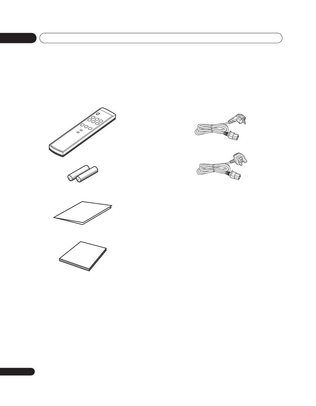
Supplied accessories
Check that all of the following accessories are supplied
in the box.
Power cord
Only the power cord appropriate for your country or
region is supplied:
Remote control unit
AA size batteries x 2
(for remote control unit)
Warranty card
Operating instructions
For Europe, except UK and Republic of Ireland
For UK and Republic of Ireland
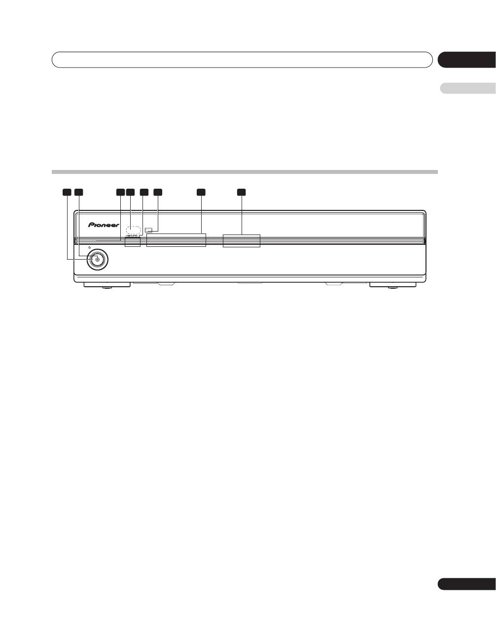
Part names
05
9
En
English
Chapter 5
Part names
Front
1
STANDBY/ON button
Press to set power to ON/STANDBY.
2
Power ON indicator (blue)
Lights blue when unit power is turned ON.
3
STANDBY indicator (red)
Lights red when unit power is set to STANDBY.
4
Remote control unit sensor
Point the remote control unit at this sensor when
operating.
5
HDMI CONTROL indicators
(Left: orange/ Right: green)
When this unit is connected to a plasma television,
these indicators light under the following conditions:
a. PDP combination mode:
Lights green when
HDMI CONTROL
switch is set to
ON
, and the unit’s connected plasma television can
be operated using the latter’s remote control unit.
(See page 10.)
b. Independent 1 mode:
Lights orange when the
HDMI CONTROL
switch is
set to
ON
. (See page 10.)
c. Independent 2 mode:
Do not light when the
HDMI CONTROL
switch is
stet to
OFF
. (See page 10.)
6
INPUT button
Use to select the unit’s source INPUT 1 to INPUT 6.
7
Input indicators
Notifies user of currently selected input and currently
set mode.
8
Blue illumination
Lights blue when unit power is turned ON. Flashes blue
during setting mode.
PDA-V100HD
STANDBY
STANDBY/ON
1
2
3
4
5
6
INPUT
INPUT
1
2
3 4
5
6
7
8
Part names
05
10
En
Rear
1
Factory adjust connector
Do not connect anything to this connector.
2
CONTROL IN/OUT connectors
Connect to Pioneer components bearing the
mark.
3
INPUT 5 connectors
(S-VIDEO, VIDEO, AUDIO)
Connect to the output connectors of components such
as Blu-ray disc (BD) players, DVD players, DVD
recorders, Set-Top Box (STB), VCRs, game machines,
camcorders, etc.
4
OUTPUT connector (HDMI)
Connect to the HDMI connector of a television
supporting the High-Definition Multimedia Interface
(HDMI).
5
INPUT 1, INPUT 3, INPUT 4, INPUT 6 connectors
(HDMI)
Connect to the HDMI connector of components
supporting the High-Definition Multimedia Interface
(HDMI), such as BD players, DVD recorders, etc.
6
INPUT 1 connectors (AUDIO)
Connect to a component’s analog audio output
connectors.
7
INPUT 2 connectors
(COMPONENT VIDEO: Y, PB, PR)
Connect to the appropriate output connectors of a BD
player, DVD player, DVD recorder, etc.
8
INPUT 2 connectors (AUDIO)
Connect to audio output connectors of BD player, DVD
player, DVD recorder, etc.
9
HDMI CONTROL switch
Set to
ON
when this unit is connected to a Pioneer
plasma television; set to
OFF
when connected to
another manufacturer’s television.
10 INPUT 3 connector (SCART)
Connect to the appropriate output connector of a BD
player, DVD player, DVD recorder, etc.
11 INPUT 4 connectors (AUDIO)
Connect to a component’s analog audio output
connectors.
12 AC IN
Connect one end of the supplied power cord to this
connector, and the other end to a household AC outlet.
HDMI
OUTPUT
INPUT 1
INPUT 3
INPUT 4
INPUT 6
INPUT 1
INPUT 2
HDMI
CONTROL
SERVICE ONLY
CONTROL
COMPONENT
VIDEO
AUDIO
L
R
L
R
AUDIO
I N
OUT
Y
P
B
P
R
ON/OFF
INPUT 3
INPUT 4
AUDIO
L
R
INPUT 5
S-VIDEO
VIDEO
R-AUDIO-L
AC IN
1
2
3
4
5
6
7
8 9
10
11
12
Part names
05
11
En
English
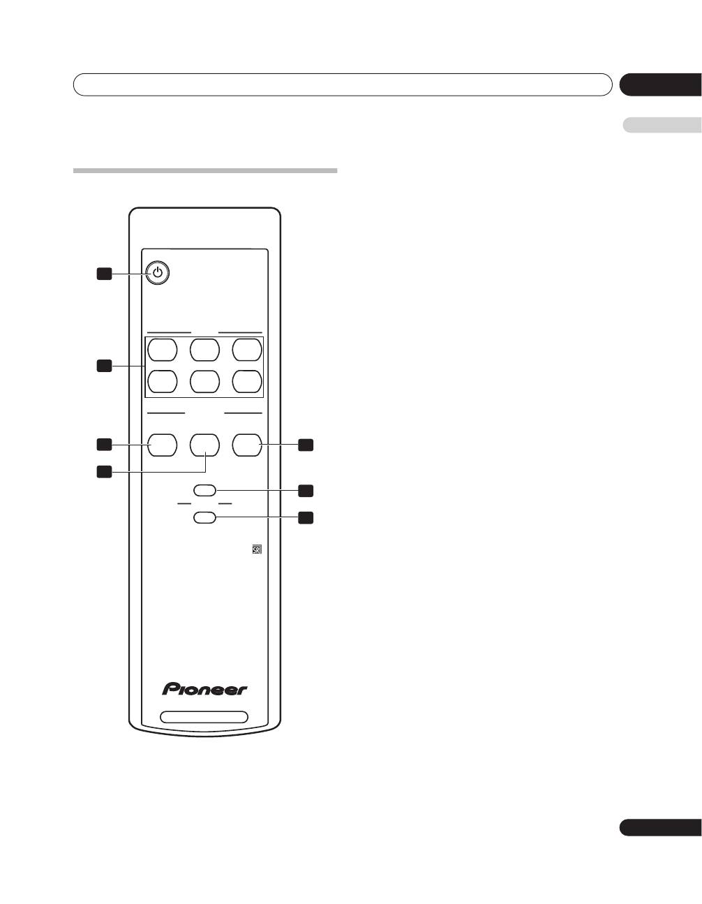
Remote control unit
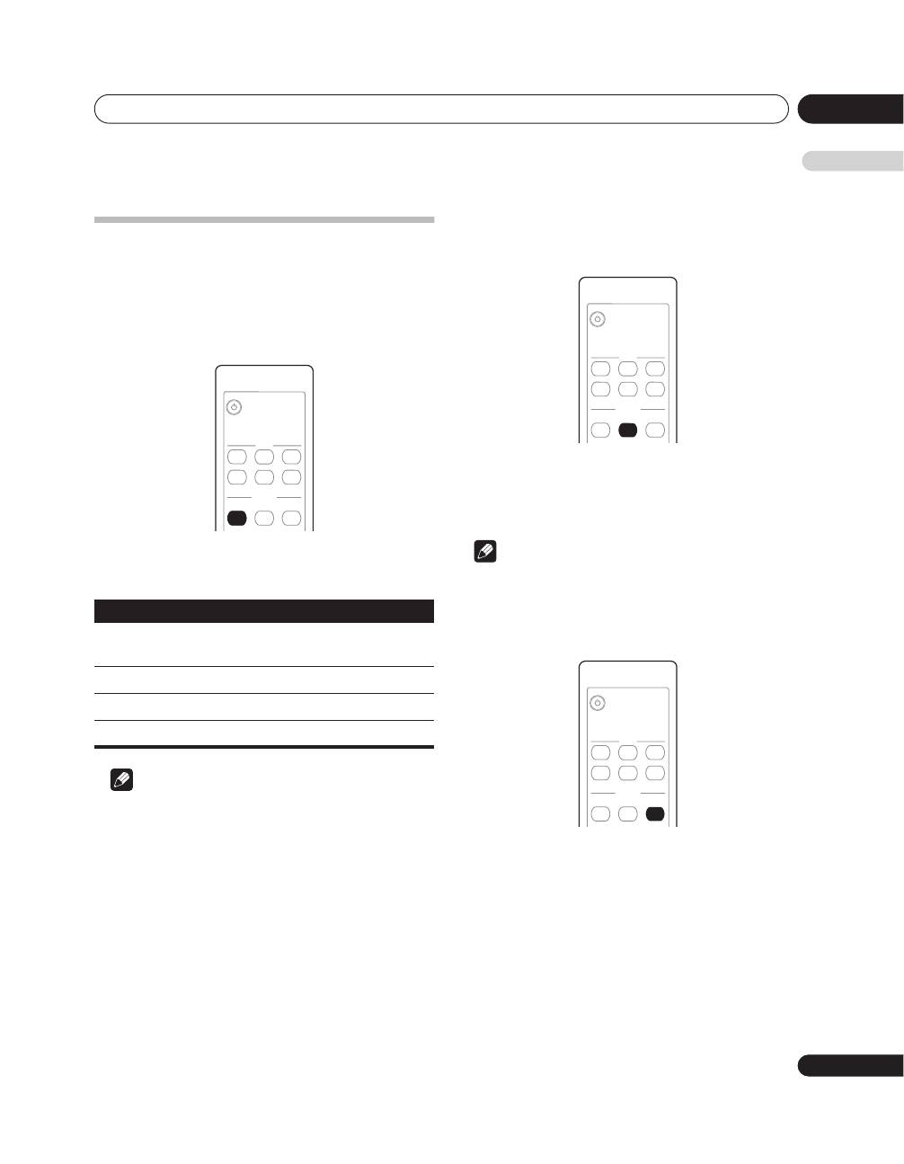
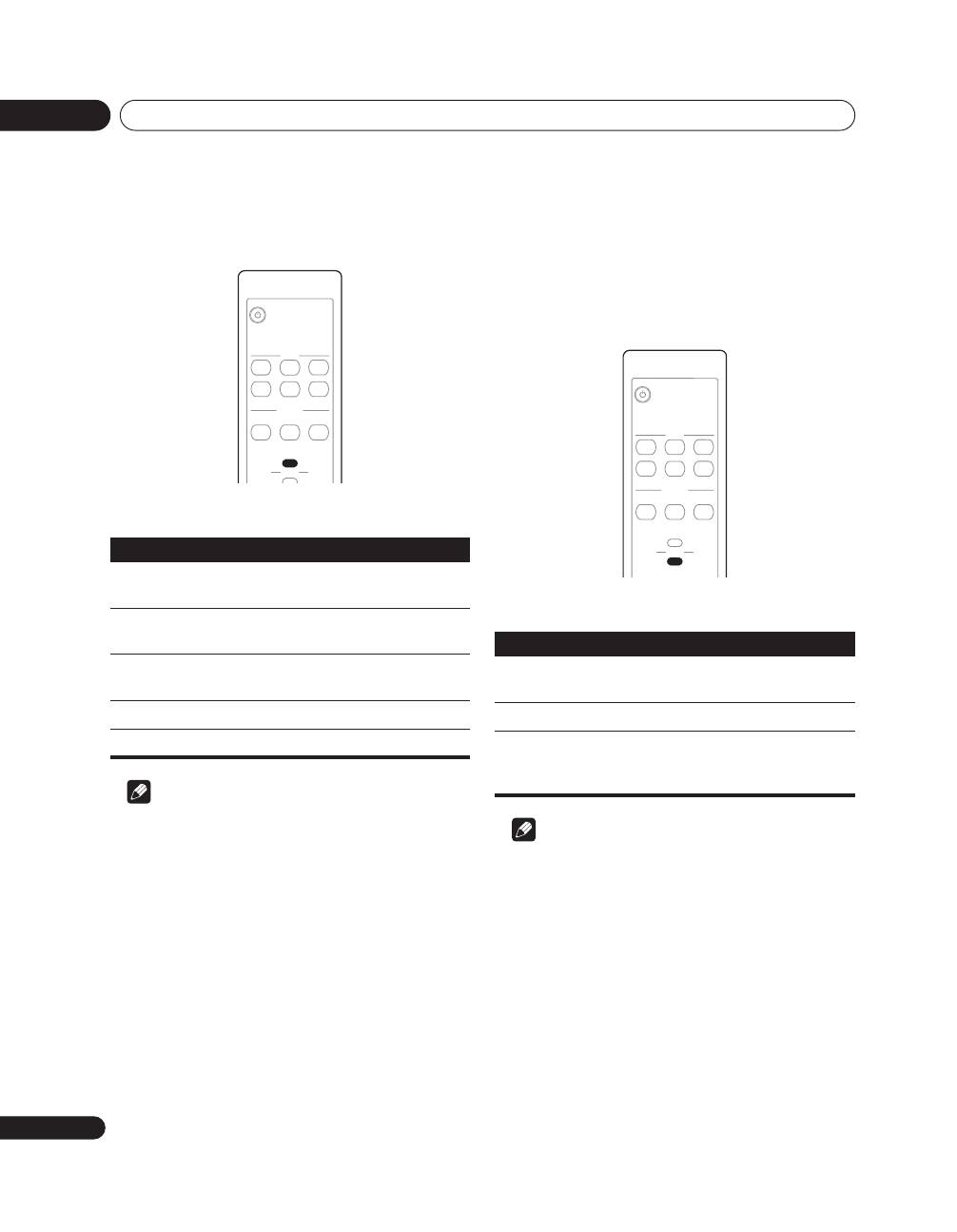
Point the remote control at the unit to operate.
1
button
Press to set power to ON/STANDBY.
2
INPUT buttons
Press to select the unit’s source INPUT 1 to INPUT 6.
3
RESOLUTION button
Use to set output resolution when converting analog
input signals to HDMI. (See page 19.)
4
COLOUR SYSTEM button
Use to set the colour system for analog input signals.
(See page 19.)
5
SIGNAL SELECT button
Use to select input signal for INPUT 3. (See page 19.)
6
VIDEO button
Use to set the colour format when converting analog
input signals to HDMI. (See page 20.)
7
AUDIO button
Use to set the type of audio signal during HDMI input.
(See page 20.)
INPUT
SETTING
RESOLUTION
COLOUR
SYSTEM
SIGNAL
SELECT
VIDEO
AUDIO
HDMI
1
2
3
4
5
6
HD AV CONVERTER
1
2
3
4
5
6
7
Preparation
06
12
En
Chapter 6
Preparation
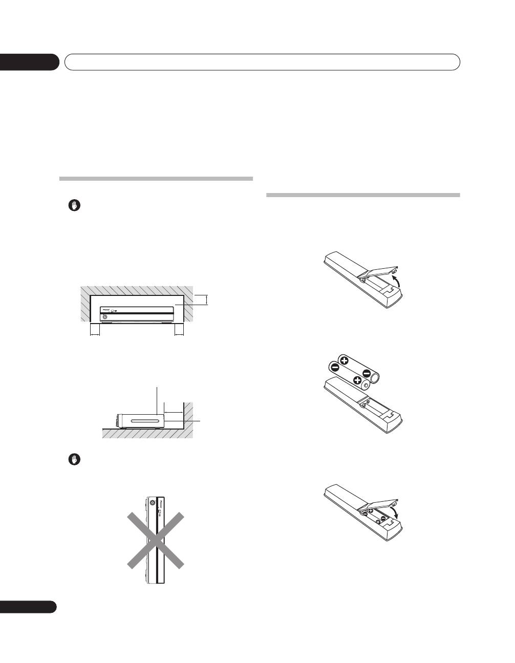
Installing the unit
Caution
•
Do not place a VCR or any other device on the
top of the unit.
•
When installing, allow enough space on the
sides and above the unit.
•
Do not block the side ventilation opening or the
rear exhaust opening of the unit.
Caution
• Placing the unit alone in the vertical position can
result in product damage and malfunction.
Preparing the remote control
unit
Inserting batteries
1
Open the battery cover.
2
Load the supplied two AA size batteries while
inserting their respective negative polarity (–) ends
first.
Place batteries with their terminals corresponding to
the (+) and (–) indicators in the battery compartment.
3
Close the battery cover.
PDA-V100HD
1
2
3
4
5
6
STANDBY
STANDBY/ON
INPUT
INPUT
Over 5 cm
Over 5 cm
Over 5 cm
Over 10 cm
Exhaust
opening
Ventilation
opening
PDA-V100HD
12
34
5
6
ST
ANDBY
ST
ANDBY/ON
Preparation
06
13
En
English
Caution
Improper use of batteries can result in chemical
leakage or an explosion. Be sure to follow the
instructions below.
• When you replace the batteries, use manganese or
alkaline ones.
• Place the batteries with their terminals
corresponding to the (+) and (–) indicators.
• Do not mix batteries of different types. Different
types of batteries have different characteristics.
• Do not mix old and new batteries. Mixing old and
new batteries can shorten the life of new batteries
or cause chemical leakage in old batteries.
• Remove batteries as soon as they have worn out.
Chemicals that leak from batteries can cause a
rash. If you find any chemical leakage, wipe
thoroughly with a cloth.
• The batteries supplied with this product may have a
shorter life expectancy due to storage conditions.
• If you will not use the remote control unit for an
extended period of time, remove the batteries from
it.
•
WHEN DISPOSING OF USED BATTERIES, PLEASE
COMPLY WITH GOVERNMENTAL REGULATIONS
OR ENVIRONMENTAL PUBLIC INSTITUTION’S
RULES THAT APPLY IN YOUR COUNTRY/AREA.
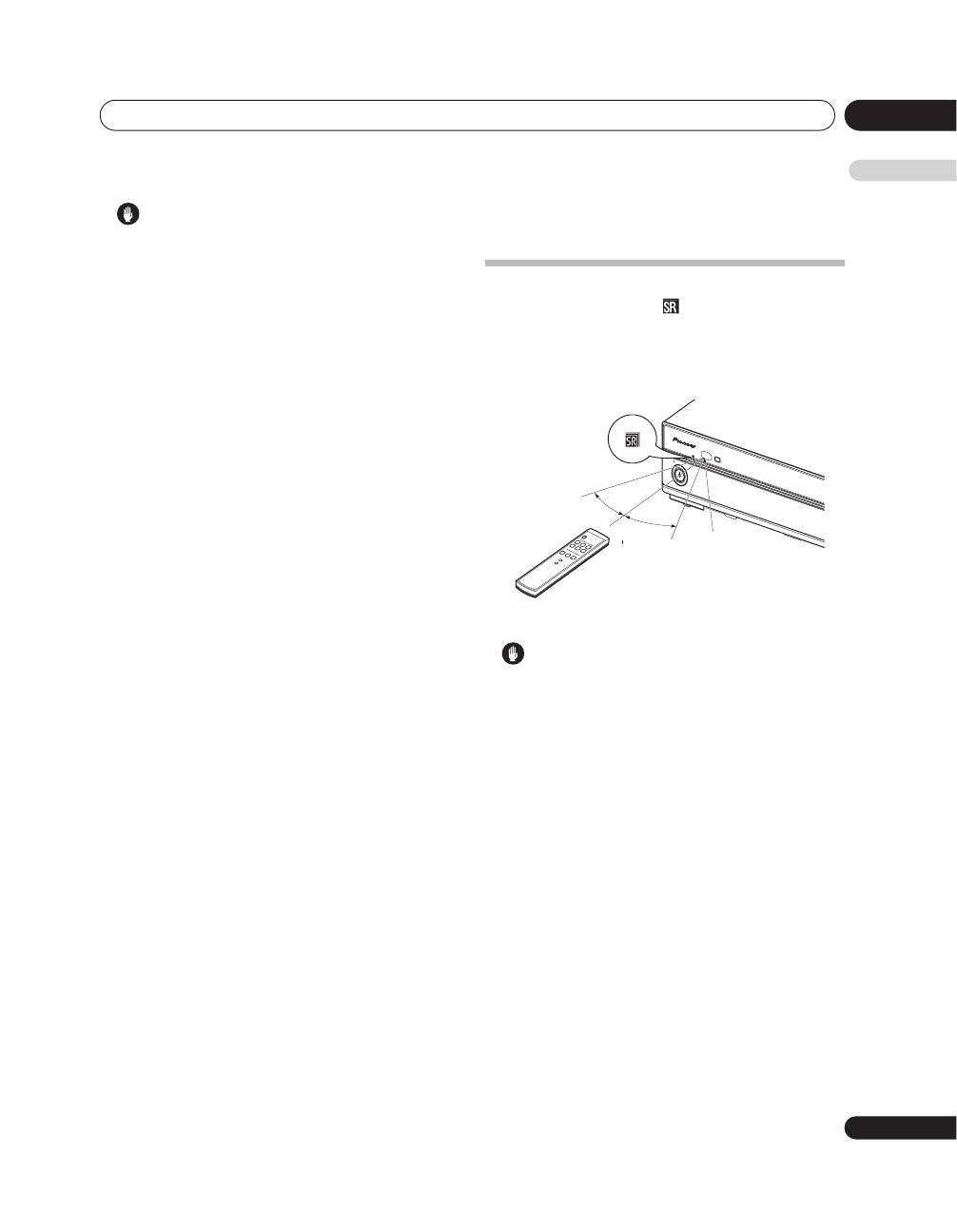
Operating range of the remote
control unit
Operate the remote control unit while pointing it toward
the remote control sensor (
) located at the left of the
front panel of the unit. The distance from the remote
control sensor must be within 7 m and the angle
relative to the sensor must be within 30 degrees in the
right, left, upward, or downward direction.
Caution
• Do not expose the remote control unit to shock. In
addition, do not expose the remote control unit to
liquids, and do not place in an area with high
humidity.
• Do not install or place the remote control unit under
direct sunlight. The heat may cause deformation of
the unit.
• The remote control unit may not work properly if the
remote control sensor of the unit is under direct
sunlight or strong lighting. In such case, change
the angle of the lighting or unit, or operate the
remote control unit closer to the remote control
sensor.
• When any obstacle exists between the remote
control unit and the remote control sensor, the
remote control unit may not function.
• As the batteries become empty, the remote control
unit can function within a shorter distance from the
remote control sensor. Replace the batteries with
new ones early enough.
1
2
3
4
5
6
STAN
DBY
HDM
I CONT
ROL
STAN
DBY/O
N
INPUT
INPUT
30 º
30 º
Remote
control
sensor
7 m

Using the unit
07
14
En
Chapter 7
Using the unit
When a Pioneer plasma television is connected and the HDMI Control function is set, the plasma television’s
remote control can be used to perform normal operations on this unit.
When using the HDMI Control function, set the rear panel
HDMI CONTROL
switch to
ON
, then use the plasma
television’s “HDMI Control Setting” menu to set the television to permit control of the unit.
This unit can also be used as an AV selector, without using the HDMI Control function. In that case, leave the
HDMI
CONTROL
switch set to
OFF
.
This unit has three operating modes when using the Pioneer HDMI Control function.
Each of the modes can be ascertained by looking at the status of the HDMI CONTROL indicators.
The unit’s operations and operation restrictions are as follows:
Operation modes
Operations/Operation restrictions
HDMI Control setting
PDP Combination Mode
Operations:
• HDMI Control function used for linked operation with
Pioneer plasma television.
• Change input selections INPUT 1 to INPUT 5 using the
remote control unit furnished with the Pioneer plasma
television.
• Power on/off linked to plasma television using the remote
control unit furnished with the Pioneer plasma television.
• When a video signal is received from a connected input
component, this unit is automatically turned on and the
input selector switched to allow output of the image from
the connected component (HDMI inputs only).
Operation restrictions:
• The
INPUT
button on PDA-V100HD and its remote control
unit are disabled.
• The component connected to INPUT 6 cannot be used.
Settings required on this unit:
HDMI CONTROL
switch:
ON
Settings required on the
Pioneer plasma television:
Set to allow linked operation
with this unit.
Independent 1 mode
Operations:
• HDMI Control function is used to link operations with
input component.
• When a video signal is detected from a connected input
component, this unit is automatically turned on and the
input selector switched to allow output of the image from
the connected component (HDMI inputs only).
• Whether power off can be linked depends on functional
support of other connected components (namely,
whether power off command can be sent from other
component).
• The
INPUT
button on PDA-V100HD and its remote control
unit can be used to switch the unit’s corresponding
INPUT 1 to INPUT 6.
Settings required on this unit:
HDMI CONTROL
switch:
ON

Using the unit
07
15
En
English
Connecting the unit to a Pioneer plasma television (see Chapter 8)
Operations, indicators, conditions, and precautions when connecting the unit to a Pioneer plasma television are as
follows:
* See the section
Features
(page 7) regarding the model numbers of supported Pioneer plasma televisions.
Connecting the unit to other televisions (see Chapter 9)
Operations, indicators, conditions, and precautions when using the unit as an AV selector are as follows:
Independent 2 mode
Operations:
• HDMI Control function is not used.
• The unit does not operate in linkage to other components,
but as an independent component.
• The
INPUT
button on PDA-V100HD and its remote control
unit can be used to switch the unit’s corresponding
INPUT 1 to INPUT 6.
Settings required on this unit:
HDMI CONTROL
switch:
OFF
Operations
• The plasma television’s remote control can be used to control the unit’s input selector.
• The unit’s power switch is linked to that of the plasma television; when the plasma television’s power
switch is set to off, this unit’s power is also automatically turned off.
Indicators
The HDMI CONTROL indicator lights green.
Conditions
• The
HDMI CONTROL
switch must be set to
ON
.
• The plasma television’s “HDMI Control Setting” menu must be set to allow control of this unit.
Note: For setting details, consult the Operating Instructions for your plasma television.
Precautions
• The
INPUT
button and the remote control’s
INPUT
(
1
to
6
) buttons cannot be used to change the
unit’s input selection.
• The input selection for the component connected to INPUT 6 connector cannot be changed.
• If the
HDMI CONTROL
switch is set from
ON
to
OFF
, be sure also to cancel the plasma television’s
“HDMI Control Setting”.
Operations
• The
INPUT
button and remote control’s
INPUT
(
1
to
6
) buttons can be used to change the unit’s input
selection.
Indicators
The HDMI CONTROL indicators do not light.
Conditions
• The
HDMI CONTROL
switch must be set to
OFF
.
Precautions
• The plasma television’s remote control cannot be used to control the unit’s input selector.
Operation modes
Operations/Operation restrictions
HDMI Control setting
Using the unit with a Pioneer plasma television
08
16
En
Chapter 8
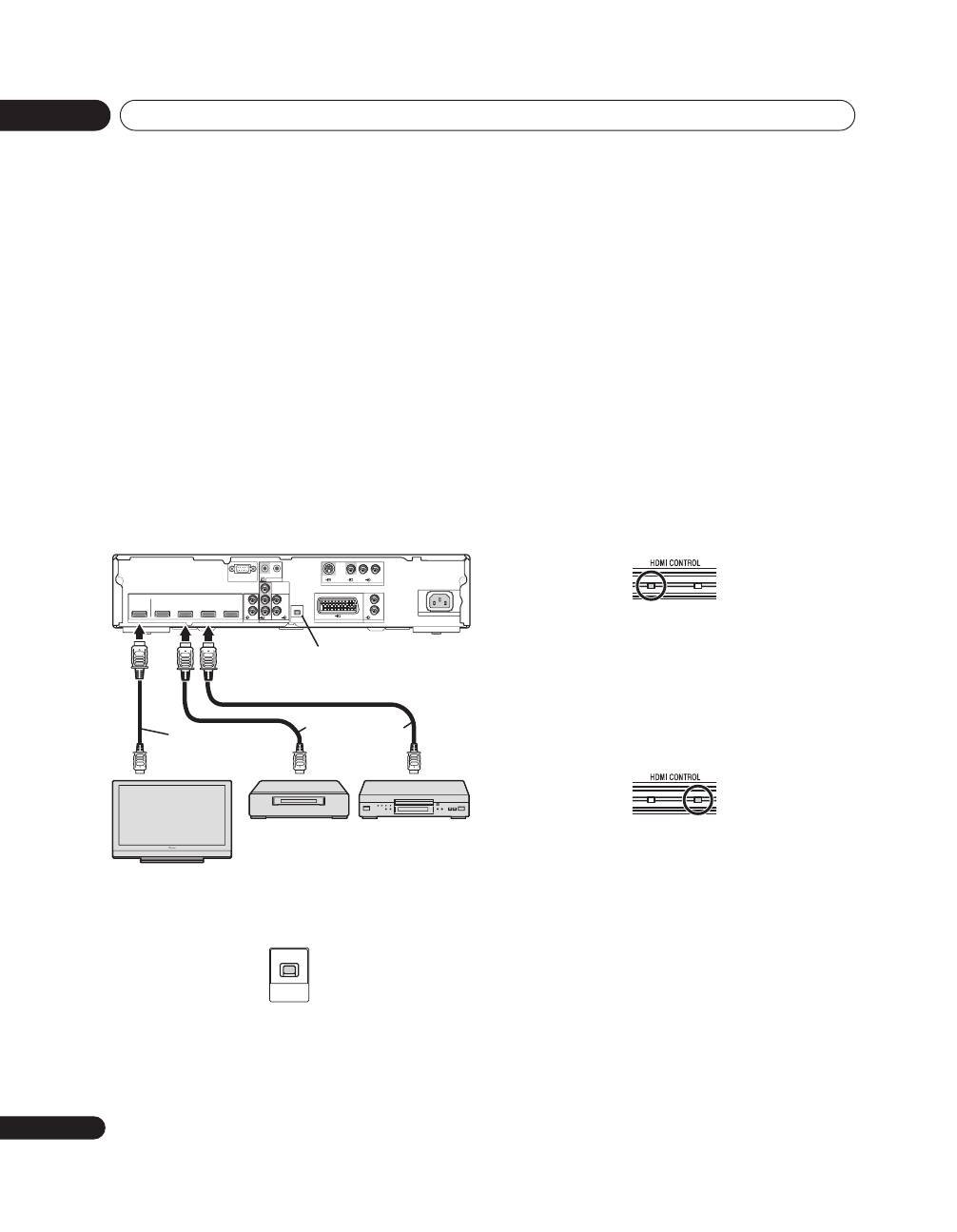
Using the unit with a Pioneer plasma television
Follow these procedures when connecting this unit to a
Pioneer plasma television.
The ability to use the HDMI Control function depends in
part on the specifications of the plasma television; as a
result, please consult the Operating Instructions for
your plasma television if you desire to use HDMI
Control.
Be sure that the power switches of both plasma
television and this unit are set to off before making
connections and settings.
1
Set this unit’s rear panel HDMI CONTROL switch
to ON.
2
Connect this unit to other components.
• Be sure power is turned off before making
connections.
• Regarding connections, see section
Using with
other components
on page 21.
• When using the plasma television’s remote signal
receiver to control this unit, consult the section
Connecting control cables
on page 18.
3
Turn power on.
• Turn power on only after connecting all other
components.
4
Confirm that the HDMI CONTROL indicator
lights orange.
5
On the plasma television’s “HDMI Control
Setting” menu, set to allow control of this unit.
• For details, see the plasma television’s Operating
Instructions.
6
Confirm that the HDMI CONTROL indicator has
changed from orange to green.
7
Select the input.
• Confirm that the input can be changed using the
plasma television’s remote control unit.
When turning power off:
If the plasma television’s “HDMI Control Setting” menu
is used to link the power controls, when the plasma
television’s remote control is used to turn the
television’s power off, this unit’s power will
simultaneously turn off.
HDMI
OUTPUT
INPUT 1
INPUT 3
INPUT 4
INPUT 6
INPUT 1
INPUT 2
HDMI
CONTROL
SERVICE ONLY
CONTROL
COMPONENT
VIDEO
AUDIO
L
R
L
R
AUDIO
I N
OUT
Y
PB
PR
ON/OFF
INPUT 3
INPUT 4
AUDIO
L
R
INPUT 5
S-VIDEO
VIDEO
R-AUDIO-L
AC IN
System composition example using HDMI connections
This unit
Plasma television
Input components
HDMI CONTROL switch
HDMI compliant cable
HDMI compliant cable
HDMI
CONTROL
ON/OFF
Using the unit with other televisions
09
17
En
English
Chapter 9
Using the unit with other televisions
Follow the procedures listed below when using this unit
as an AV selector.
Be sure that the power switches of both television set
and this unit are set to off before making connections
and settings.
1
Set the HDMI CONTROL switch to OFF.
2
Connect this unit to other components.
• Be sure power is turned off before making
connections.
• Regarding connections, see section
Using with
other components
on page 21.
3
Turn power on.
• Turn power on only after connecting all other
components.
4
Confirm that the HDMI CONTROL indicators are
not lighted.
5
Select the input.
• Confirm that the
INPUT
button and the remote
control unit’s
INPUT
(
1
to
6
) buttons can be used to
change the source input.
When turning power off:
Press the
STANDBY/ON
button or the remote control
unit’s
button to turn power off.
HDMI
CONTROL
ON/OFF
Advanced functions
10
18
En
Chapter 10
Advanced functions
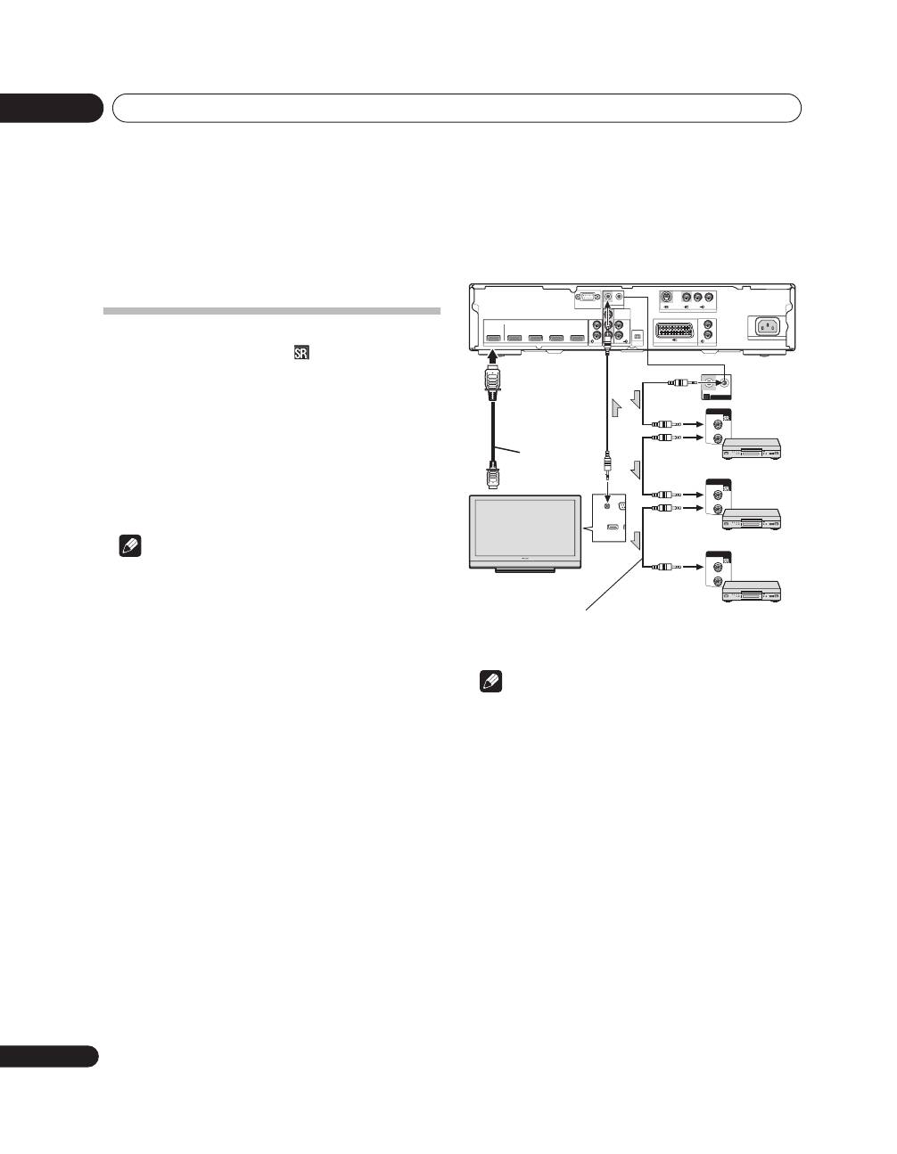
Connecting control cables
Connect control cables between the unit and other
Pioneer equipment having the
logo. You can then
operate the connected equipment by sending
commands from its remote control unit to the remote
control sensor on the unit.
After the CONTROL IN/OUT terminals have been
connected, the remote control sensors on the
connected equipment do not accept commands from
the remote control units. Face the remote control units
to the remote control sensors on the unit when
operating the connected equipment.
Note
• Make sure that the power is turned off when making
connections.
• Complete all component connections before
making control cable connections.
The control cables (commercially available) are mono
sound cables with mini plugs (no resistance).
Note
• When connecting the control connector, be sure to
simultaneously connect analog audio cables or
video cables. System control will not operate
properly when digital connections alone are made.
• When using SR connections to a Pioneer plasma
television, point the unit’s remote control at the
plasma television’s signal sensor when operating.
HDMI compliant
cable
Plasma television
Rear view
HDMI
OUTPUT
INPUT 1
INPUT 3
INPUT 4
INPUT 6
INPUT 1
INPUT 2
HDMI
CONTROL
SERVICE ONLY
CONTROL
COMPONENT
VIDEO
AUDIO
L
R
L
R
AUDIO
I N
OUT
Y
PB
PR
ON/OFF
INPUT 3
INPUT 4
AUDIO
L
R
INPUT 5
S-VIDEO
VIDEO
R-AUDIO-L
AC IN
CONTROL
I N
OUT
CONTROL
IN
OUT
CONTROL
IN
OUT
CONTROL
IN
OUT
Advanced functions
10
19
En
English
Changing settings
Changing HDMI output resolution
When converting analog input signals to HDMI, the
output resolution must be set.
This setting is supported when the currently selected
input is INPUT 2, INPUT 3 (SCART), or INPUT 5.
•
Press the remote control unit’s RESOLUTION
button.
The following items can be set:
Note
• Under normal conditions, leave this set to Auto.
Selecting the colour system
Select the colour system for analog input signals.
This setting is supported when the currently selected
input is INPUT 3 (SCART), or INPUT 5.
•
Press the remote control unit’s COLOUR
SYSTEM button.
The system can be set to Auto (default), PAL, SECAM,
NTSC, 4.43NTSC or PAL60.
Note
• Under normal conditions, leave this set to Auto.
Selecting the INPUT3 source signal
Select the INPUT 3 source signal.
•
Press the remote control unit’s SIGNAL SELECT
button.
The signal can be selected from among VIDEO
(default), S-VIDEO, RGB, or HDMI.
Item
Description
Auto
(default)
Resolution is set automatically in
response to the input signal.
480p/576p
Switch to 480p/576p resolution
720p
Switch to 720p resolution
1080i
Switch to 1080i resolution
INPUT
SETTING
RESOLUTION
COLOUR
SYSTEM
SIGNAL
SELECT
1
2
3
4
5
6
INPUT
SETTING
RESOLUTION
COLOUR
SYSTEM
SIGNAL
SELECT
1
2
3
4
5
6
INPUT
SETTING
RESOLUTION
COLOUR
SYSTEM
SIGNAL
SELECT
1
2
3
4
5
6
Advanced functions
10
20
En
Setting the video signal format
When converting analog input signals to HDMI, set the
colour format.
•
Press the remote control unit’s VIDEO button.
The following items can be set:
Note
• Under normal conditions, leave this set to Auto.
Setting the audio signal when using HDMI
input
When using an HDMI input, set the audio signal
format.
This setting is supported when the currently selected
input is INPUT 1 (HDMI), INPUT 3 (HDMI), or INPUT 4
(HDMI).
•
Press the remote control unit’s AUDIO button.
The following items can be set:
Note
• Under normal conditions, leave this set to Auto.
• This setting cannot be made for INPUT 6, since
analog audio connectors are not provided.
Item
Description
Auto
(default)
Automatically sets the signal format in
response to the input signal.
Colour-1
Digital Component Video signals (4:2:2)
locked
Colour-2
Digital Component Video signals (4:4:4)
locked
Colour-3
Digital RGB signals (16 to 235) locked
Colour-4
Digital RGB signals (0 to 255) locked
INPUT
SETTING
RESOLUTION
COLOUR
SYSTEM
SIGNAL
SELECT
VIDEO
AUDIO
HDMI
1
2
3
4
5
6
Item
Description
Auto
(default)
Audio signal format is set automatically
in response to the type of input signal.
Digital
Plays only HDMI digital audio.
Analogue
When both HDMI and analog connec-
tors are connected, analog signals only
are played.
INPUT
SETTING
RESOLUTION
COLOUR
SYSTEM
SIGNAL
SELECT
VIDEO
AUDIO
HDMI
1
2
3
4
5
6
