Pioneer VSX-421: Using the component video jacks Connecting antennas
Using the component video jacks Connecting antennas: Pioneer VSX-421
Table of contents
- AUDIO/VIDEO MULTI-CHANNEL RECEIVER
- IMPORTANT IMPORTANT: THE MOULDED PLUG VENTILATION CAUTION
- WARNING
- Contents
- Before you start
- Remote control
- Connecting your equipment
- Connecting the speakers
- Making cable connections HDMI cables
- Analog audio cables Digital audio cables Video cables About video outputs connection
- Connecting your component with no HDMI terminal Connecting a TV and playback components Connecting using HDMI
- Connecting a satellite receiver or other digital set-top box Connecting an HDD/DVD recorder, Blu-ray Disc recorder and other video sources Connecting other audio components
- Using the component video jacks Connecting antennas
- Using external antennas Plugging in the receiver Canceling the demo display
- Basic playback
Connecting your equipment
13
En
English
Français
Italiano
Nederlands
Español
Deutsch
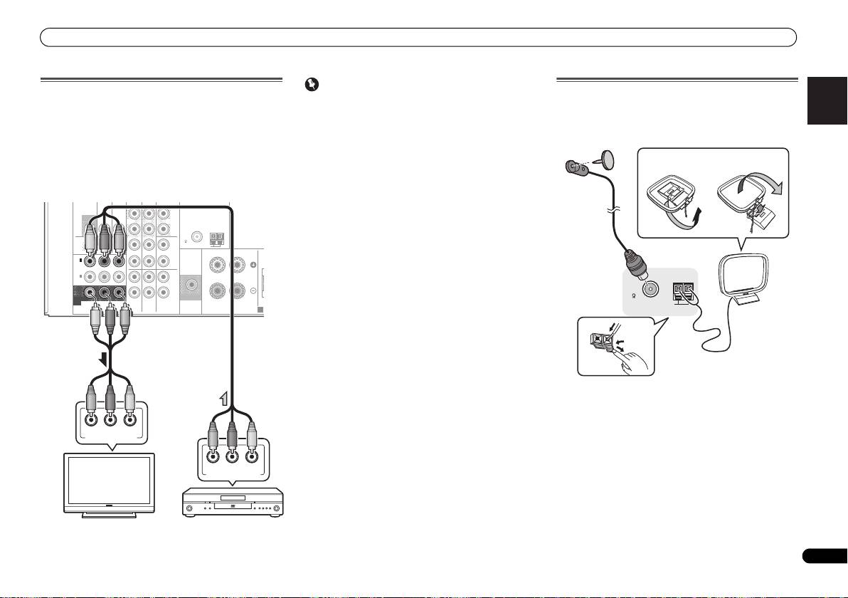
Using the component video jacks
Component video should deliver superior picture quality
when compared to composite video. A further advantage (if
your source and TV are both compatible) is progressive-scan
video, which delivers a very stable, flicker-free picture. See
the manuals that came with your TV and source component
to check whether they are compatible with progressive-scan
video.
• For the audio connection, refer to Connecting your
component with no HDMI terminal on page 11.
Important
Connecting antennas
• If you connect any source component to the receiver
Connect the AM loop antenna and the FM wire antenna as
using a component video input, you must also have your
shown below. To improve reception and sound quality,
TV connected to this receiver’s COMPONENT VIDEO
connect external antennas (see Using external antennas
MONITOR OUT jacks.
below).
• If necessary, assign the component video inputs to the
input source you’ve connected. This only needs to be
done if you didn’t connect according to the following
defaults:
-
COMPONENT VIDEO IN 1: DVD
DVR
-
COMPONENT VIDEO IN 2: DVR/BDR
See The Input Assign menu on Operating Instructions in
CD-ROM for more on this.
ANTENNA
DVR /
BDR
L
R
ASSIGNABLE
L
R
YP
B
P
R
COMPONENT
VIDEO
PRE OUT
SPEAKERS
A
1
Push open the tabs, then insert one wire fully into each
terminal, then release the tabs to secure the AM antenna
wires.
2
Fix the AM loop antenna to the attached stand.
To fix the stand to the antenna, bend in the direction
indicated by the arrow (fig. a) then clip the loop onto the
stand (fig. b).
3
Place the AM antenna on a flat surface and in a direction
giving the best reception.
4
Connect the FM wire antenna into the FM antenna
socket.
For best results, extend the FM antenna fully and fix to a wall
or door frame. Don’t drape loosely or leave coiled up.
/
BDR
OUT
C
D-R
/
TAPE
SURR BACK
L
MONITOR
TV/SAT
BD
(
Single
)
OUT
IN
IN
PRE OUT
R
FM
CD
UNBAL
75
AM LOOP
OUT
IN
DVD IN
IN IN
RL
FRONT
IN
1
C
(
DVD
)
IN
2
(
DVR /
BDR
)
IN
IN
MONITOR
SUBWOOFER
OUT
TV/SAT
BD
DVD
PR
P
B
Y
COMPONENT VIDEO IN
PR
P
B
Y
COMPONENT VIDEO OUT
TV
DVD player
2
4
ANTENNA
FM
UNBAL
75
AM LOOP
3
1
fig. a
fig. b
VSX-421_SYXCN_QSG_En.book 13 ページ 2011年3月7日 月曜日 午後4時25分
