Pioneer VSX-421: Analog audio cables Digital audio cables Video cables About video outputs connection
Analog audio cables Digital audio cables Video cables About video outputs connection: Pioneer VSX-421
Table of contents
- AUDIO/VIDEO MULTI-CHANNEL RECEIVER
- IMPORTANT IMPORTANT: THE MOULDED PLUG VENTILATION CAUTION
- WARNING
- Contents
- Before you start
- Remote control
- Connecting your equipment
- Connecting the speakers
- Making cable connections HDMI cables
- Analog audio cables Digital audio cables Video cables About video outputs connection
- Connecting your component with no HDMI terminal Connecting a TV and playback components Connecting using HDMI
- Connecting a satellite receiver or other digital set-top box Connecting an HDD/DVD recorder, Blu-ray Disc recorder and other video sources Connecting other audio components
- Using the component video jacks Connecting antennas
- Using external antennas Plugging in the receiver Canceling the demo display
- Basic playback
Connecting your equipment
Analog audio cables
Use stereo RCA phono cables to connect analog audio
components. These cables are typically red and white, and
you should connect the red plugs to R (right) terminals and
white plugs to L (left) terminals.
Digital audio cables
Commercially available coaxial digital audio cables or optical
cables should be used to connect digital components to this
receiver.
10
En
Note
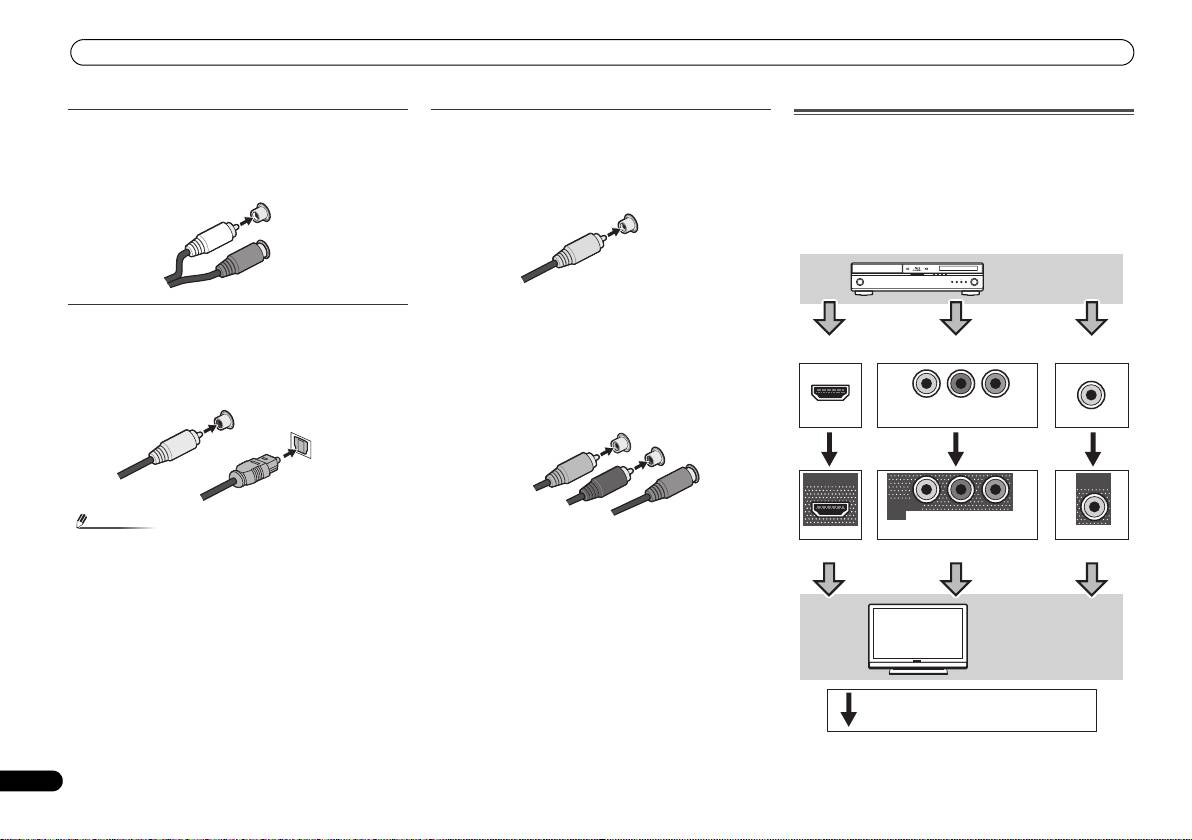
Video cables
About video outputs connection
This receiver is not loaded with a video converter. When you
Standard RCA video cables
use component video cables or HDMI cables for connecting
These cables are the most common type of video connection
to the input device, the same cables should be used for
and are used to connect to the composite video terminals.
connecting to the TV.
The yellow plugs distinguish them from cables for audio.
The signals input from the analog (composite and
L
component) video inputs of this unit will not be output from
AUDIO
the HDMI OUT.
R
Component video cables
Use component video cables to get the best possible color
reproduction of your video source. The color signal of the TV
is divided into the luminance (Y) signal and the color (P
B and
P
R) signals and then output. In this way, interference between
the signals is avoided.
• When connecting optical cables, be careful when
inserting the plug not to damage the shutter protecting
the optical socket.
• When storing optical cable, coil loosely. The cable may be
damaged if bent around sharp corners.
• You can also use a standard RCA video cable for coaxial
digital connections.
White (Left)
Red (Right)
COAXIAL
IN
OPTICAL
IN
Coaxial digital
audio cable
Optical cable
VIDEO
Yellow
COMPONENT VIDEO
Y
P
B
P
R
Green (Y)
Blue (PB)
Red (PR)
IN
IN
IN
YP
B
P
R
HDMI
COMPONENT VIDEO
VIDEO
OUT
MONITOR
OUT
MONITOR
OUT
YP
B
P
R
HDMI
COMPONENT VIDEO
VIDEO
Playback
component
Terminal for connection with source device
Terminal for connection with TV monitor
TV
Video signals can be output.
VSX-421_SYXCN_QSG_En.book 10 ページ 2011年3月7日 月曜日 午後4時25分
