Pioneer DJM-900SRT: MIDI assignment map Category
MIDI assignment map Category: Pioneer DJM-900SRT
Table of contents
- Contents
- Before start
- Installing the software
- Installation Procedure (Windows) Installing the Serato DJ software Installation procedure (Mac OS X)
- Installation Procedure (Windows) Installation procedure (Mac OS X) 9 Log in.
- 11 Read the terms of the license agreement carefully, and if you agree, click [Agree].
- Connections Rear panel
- Connecting input terminals Connecting output terminals
- Connecting to the control panel Connecting this unit and computer
- Operation Control Panel
- Basic Operation
- Advanced Operations About PRO DJ LINK Using the QUANTIZE function
- Using the FADER START function Using the SOUND COLOR FX function Using the BEAT EFFECT function Using the LINK MONITOR function
- Operating DJ software using the MIDI function Operating the [X-PAD]
- Operating an external MIDI sequencer
- Types of effects Types of SOUND COLOR FX effects Types of BEAT EFFECT
- MIDI assignment map Category
- Category
- Changing the settings About the auto standby function About the talk over function Setting preferences About the setting utility software
- Adjusting the buffer size (when using Windows ASIO) Setting the audio data output from this unit to the computer Checking the version of the driver software Checking the latest information on the driver software
- Additional information Troubleshooting
- Block Diagram
- Acquiring the manual About trademarks and registered trademarks
- Specifications
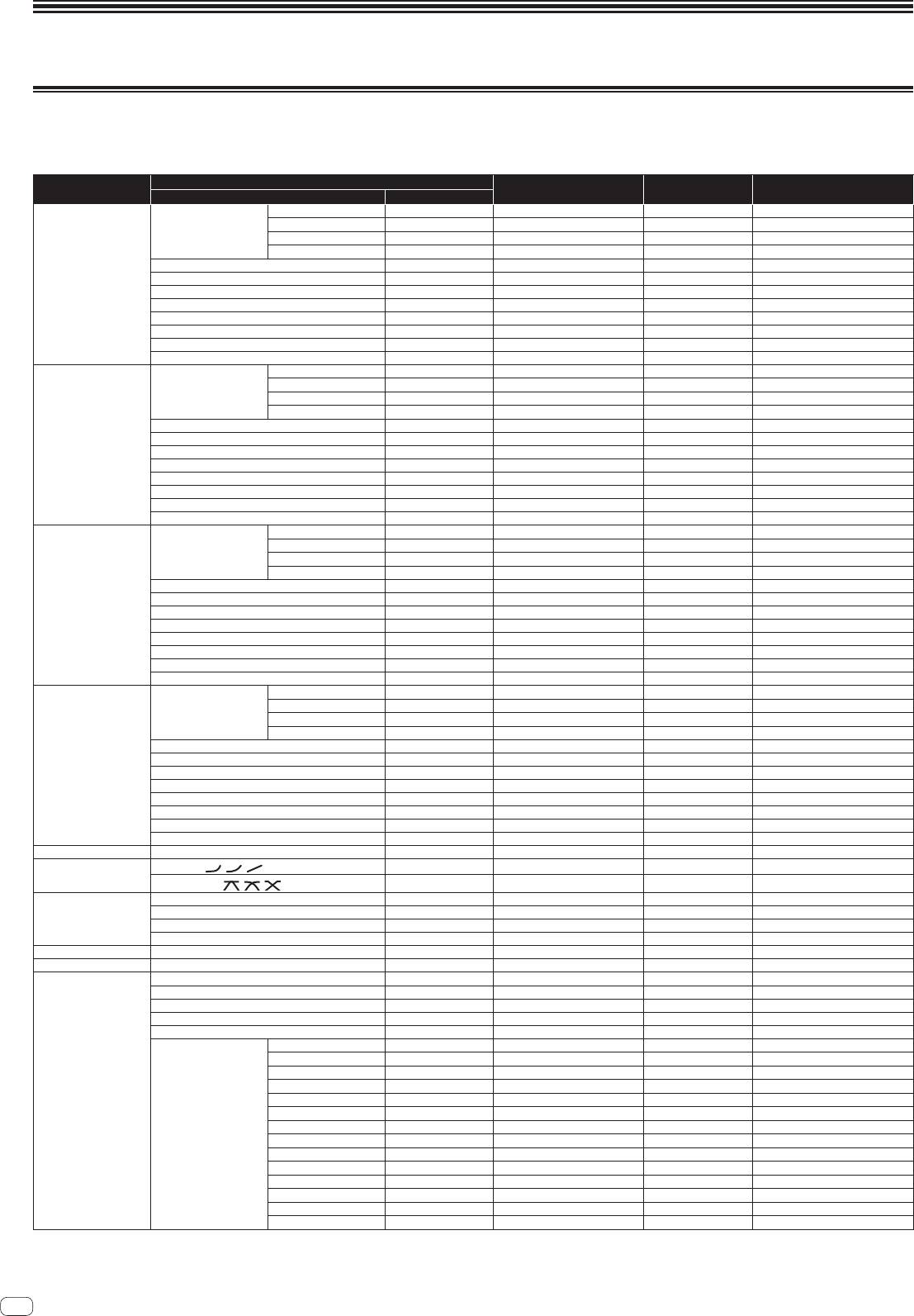
MIDI assignment map
MIDI assignment map
“CC” is the abbreviation of “control change”. A control change is a type of MIDI signal used to transmit various types of control information, such as timbre, volume, etc.
On this unit, values from 0 to 127 are output as CC mainly when controls and faders are operated. CC are also output when certain buttons are operated.
“Note” is a MIDI term used when pressing or releasing notes on a piano or other keyboard.
Button/Control/Switch
Category
MIDI assignment Trigger/Toggle Transmitted data
Name Type
DIGITAL
Switch Note 050
2
OFF=0, ON=127
CD/LINE
Switch Note 051
2
OFF=0, ON=127
Input Selector Switch
PHONO
Switch Note 052
2
OFF=0, ON=127
USB DECK 3
Switch Note 053
2
OFF=0, ON=127
TRIM
Control CC 001 — 0-127
HI
Control CC 002 — 0-127
CH1
MID
Control CC 003 — 0-127
LOW
Control CC 004 — 0-127
COLOR
Control CC 005 — 0-127
CUE
Button CC 070 Trigger/Toggle OFF=0, ON=127
Channel fader Control CC 017 — 0-127
CROSS FADER ASSIGN
Switch CC 065 — 0, 64, 127
DIGITAL
Switch Note 054
2
OFF=0, ON=127
CD/LINE
Switch Note 055
2
OFF=0, ON=127
Input Selector Switch
PHONO
Switch Note 056
2
OFF=0, ON=127
USB DECK 1
Switch Note 057
2
OFF=0, ON=127
TRIM
Control CC 006 — 0-127
HI
Control CC 007 — 0-127
CH2
MID
Control CC 008 — 0-127
LOW
Control CC 009 — 0-127
COLOR
Control CC 010 — 0-127
CUE
Button CC 071 Trigger/Toggle OFF=0, ON=127
Channel fader Control CC 018 — 0-127
CROSS FADER ASSIGN
Switch CC 066 — 0, 64, 127
DIGITAL
Switch Note 058
2
OFF=0, ON=127
CD/LINE
Switch Note 059
2
OFF=0, ON=127
Input Selector Switch
PHONO
Switch Note 060
2
OFF=0, ON=127
USB DECK 2
Switch Note 061
2
OFF=0, ON=127
TRIM
Control CC 012 — 0-127
HI
Control CC 014 — 0-127
CH3
MID
Control CC 015 — 0-127
LOW
Control CC 021 — 0-127
COLOR
Control CC 022 — 0-127
CUE
Button CC 072 Trigger/Toggle OFF=0, ON=127
Channel fader Control CC 019 — 0-127
CROSS FADER ASSIGN
Switch CC 067 — 0, 64, 127
DIGITAL
Switch Note 062
2
OFF=0, ON=127
CD/LINE
Switch Note 063
2
OFF=0, ON=127
Input Selector Switch
PHONO
Switch Note 064
2
OFF=0, ON=127
USB DECK 4
Switch Note 065
2
OFF=0, ON=127
TRIM
Control CC 080 — 0-127
HI
Control CC 081 — 0-127
CH4
MID
Control CC 092 — 0-127
LOW
Control CC 082 — 0-127
COLOR
Control CC 083 — 0-127
CUE
Button CC 073 Trigger/Toggle OFF=0, ON=127
Channel fader Control CC 020 — 0-127
CROSS FADER ASSIGN
Switch CC 068 — 0, 64, 127
Crossfader Crossfader Control CC 011 — 0-127
CH FADER (
, , )
Switch CC 094 — 0, 64, 127
Fader curve
CROSS FADER ( , , )
Switch CC 095 — 0, 64, 127
MASTER LEVEL
Control CC 024 — 0-127
BALANCE
Control CC 023 — 0-127
Master
CUE
Button CC 074 Trigger/Toggle OFF=0, ON=127
EQ CURVE (ISOLATOR, EQ) Switch CC 033 — 0, 127
BOOTH MONITOR BOOTH MONITOR
Control CC 025 — 0-127
LINK CUE
Button CC 115 Trigger/Toggle OFF=0, ON=127
Button CC 076 Trigger/Toggle OFF=0, ON=127
Button CC 077 Trigger/Toggle OFF=0, ON=127
AUTO/TAP
Button CC 069 Trigger/Toggle OFF=0, ON=127
TAP
Button CC 078 Trigger only OFF=0, ON=127
CUE
Button CC 075 Trigger/Toggle OFF=0, ON=127
DELAY
Switch CC 042
2
OFF=0, ON=127
ECHO
Switch CC 055
2
OFF=0, ON=127
SPIRAL
Switch CC 043
2
OFF=0, ON=127
REVERB
Switch CC 054
2
OFF=0, ON=127
BEAT EFFECTS
TRANS
Switch CC 053
2
OFF=0, ON=127
FILTER
Switch CC 059
2
OFF=0, ON=127
FLANGER
Switch CC 050
2
OFF=0, ON=127
EFFECT SELECT
PHASER
Switch CC 057
2
OFF=0, ON=127
ROBOT
Switch CC 051
2
OFF=0, ON=127
MELODIC
Switch CC 061
2
OFF=0, ON=127
SLIP ROLL
Switch CC 058
2
OFF=0, ON=127
ROLL
Switch CC 046
2
OFF=0, ON=127
REV ROLL
Switch CC 047
2
OFF=0, ON=127
SND/RTN (MIDI LFO) Switch CC 062
2
OFF=0, ON=127
22
En
