Pioneer DJM-900SRT: Connections Rear panel
Connections Rear panel: Pioneer DJM-900SRT
Table of contents
- Contents
- Before start
- Installing the software
- Installation Procedure (Windows) Installing the Serato DJ software Installation procedure (Mac OS X)
- Installation Procedure (Windows) Installation procedure (Mac OS X) 9 Log in.
- 11 Read the terms of the license agreement carefully, and if you agree, click [Agree].
- Connections Rear panel
- Connecting input terminals Connecting output terminals
- Connecting to the control panel Connecting this unit and computer
- Operation Control Panel
- Basic Operation
- Advanced Operations About PRO DJ LINK Using the QUANTIZE function
- Using the FADER START function Using the SOUND COLOR FX function Using the BEAT EFFECT function Using the LINK MONITOR function
- Operating DJ software using the MIDI function Operating the [X-PAD]
- Operating an external MIDI sequencer
- Types of effects Types of SOUND COLOR FX effects Types of BEAT EFFECT
- MIDI assignment map Category
- Category
- Changing the settings About the auto standby function About the talk over function Setting preferences About the setting utility software
- Adjusting the buffer size (when using Windows ASIO) Setting the audio data output from this unit to the computer Checking the version of the driver software Checking the latest information on the driver software
- Additional information Troubleshooting
- Block Diagram
- Acquiring the manual About trademarks and registered trademarks
- Specifications
Connections
Be sure to turn off the power and unplug the power cord from the power outlet whenever making or changing connections.
Connect the power cord after all the connections between devices have been completed.
Be sure to use the included power cord.
Refer to the operating instructions for the component to be connected.
When creating a DVS (Digital Vinyl System) combining a computer, audio interface, etc., be careful in connecting the audio interface to this unit’s input terminals and in
the settings of the input selector switches.
Also refer to the operating instructions of the DJ software and audio interface.
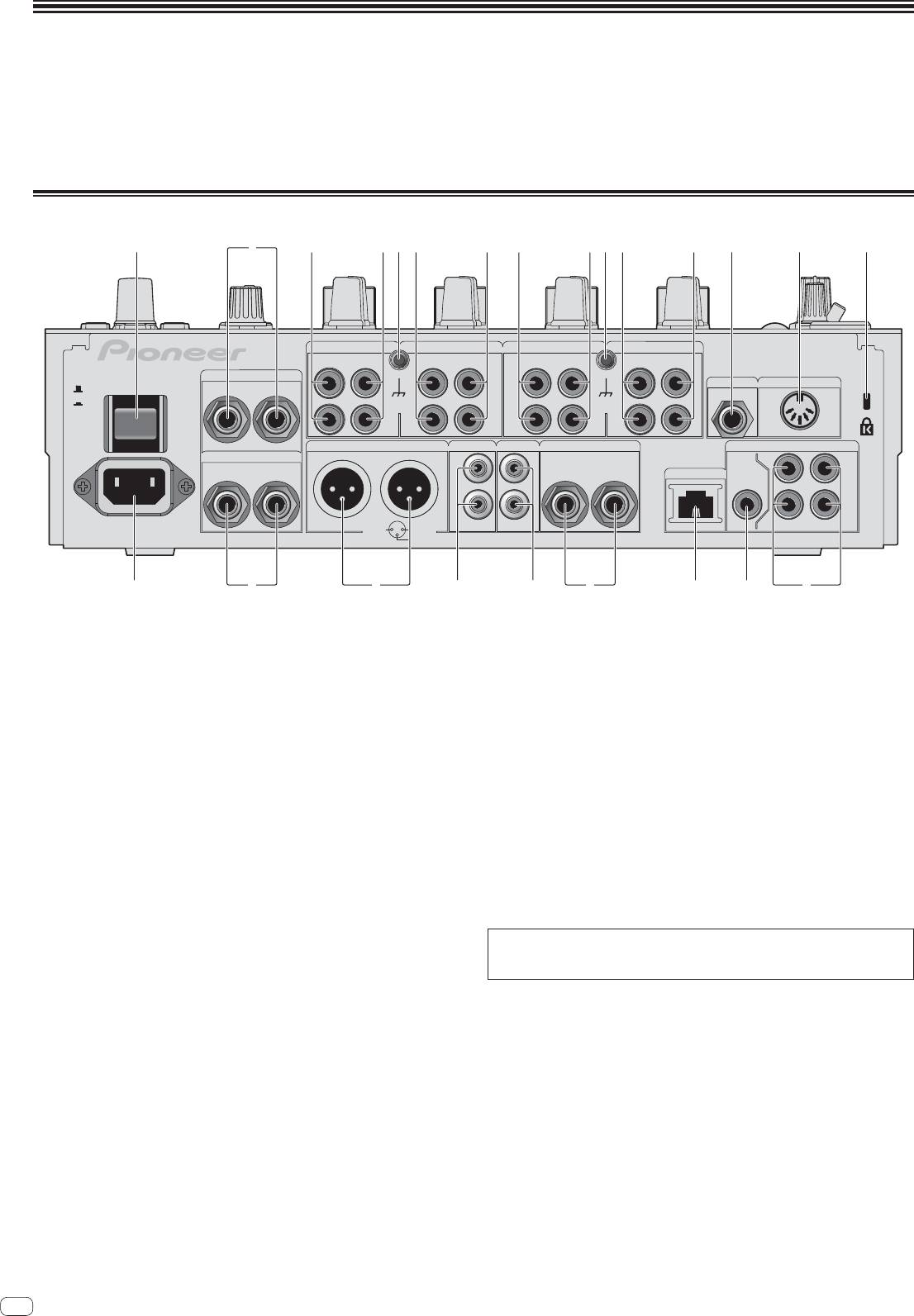
Rear panel
1 34 3443 435 5 6 7 82
CH 4 CH 3
CH 2
CH 1
PHONO PHONO PHONO
CD/ LINE
CD/ LINE
CD/ LINE
PHONO
CD/ LINE
L
L
L
L
RETURN
R
L
(MONO)
MIC2
MIDI OUT
OFF
POWER
ON
SIGNAL GND SIGNAL GND
R
R
R
R
MASTER1 MASTER2
REC OUT
BOOTH
DIGITAL
SEND
R
L
L
L
TRS
CH1CH2
LR
(MONO)
R
L
LINK
MASTER
OUT
IN
R
R
AC IN
CH4
CH3
1 GND
2 HOT
3 COLD
de abh 9cg f
1 POWER button (page 14)
c BOOTH terminals (page 11)
Turns this unit’s power on and off.
These are output terminals for a booth monitor.
2 RETURN terminals (page 11)
d REC OUT terminals (page 11)
Connect to the output terminal of an external effector. When the [L (MONO)]
These are output terminals for recording.
channel only is connected, the [L (MONO)] channel input is simultaneously
input to the [R] channel.
e MASTER2 terminals (page 11)
Connect to a power amplifier, etc.
3 PHONO terminals (page 11)
Connect to a phono level (MM cartridge) output device. Do not input line level
f MASTER1 terminals (page 11)
signals.
Connect to a power amplifier, etc.
To connect a device to the [PHONO] terminals, remove the short-circuit pin plug
Be sure to use these as balanced outputs. Be careful not to accidentally
inserted in the terminals.
insert the power cord of another unit.
Insert this short-circuit pin plug into the [PHONO] terminals when nothing is
g SEND terminals (page 11)
connected to them to cut external noise.
Connect to the input terminal of an external effector. When the [L (MONO)]
4 CD/LINE terminals (page 11)
channel only is connected, a monaural audio signal is output.
Connect to a DJ player or a line level output component.
h AC IN
5 SIGNAL GND terminal (page 11)
Connects to a power outlet using the included power cord. Wait until all connec-
Connects an analog player’s ground wire here. This helps reduce noise when the
tions between the equipment are completed before connecting the power cord.
analog player is connected.
Be sure to use the included power cord.
WARNING
6 MIC2 terminal (page 11)
The short-circuit pin plugs out of the reach of children and infants. If accidentally
Connects a microphone here.
swallowed, contact a doctor immediately.
7 MIDI OUT terminal (page 11)
Connects this to the MIDI IN terminal on an external MIDI sequencer.
8 Kensington security slot
9 DIGITAL IN terminal (page 11)
Connect these to the digital coaxial output terminals on DJ players, etc. The
sound may be momentarily interrupted when the output signal sampling fre-
quency is switched.
a DIGITAL MASTER OUT terminal (page 11)
Outputs the master channel audio signals.
b LINK terminal (page 11)
Connect these to the LINK terminals on Pioneer DJ players or the LAN ports of
computers on which rekordbox is installed (PRO DJ LINK).
To connect multiple devices, use a switching hub (commercially available).
Use a 100Base-TX-compatible switching hub. Some switching hubs may not
operate properly.
10
En
