Pioneer DJM-900SRT: Operation Control Panel
Operation Control Panel: Pioneer DJM-900SRT
Table of contents
- Contents
- Before start
- Installing the software
- Installation Procedure (Windows) Installing the Serato DJ software Installation procedure (Mac OS X)
- Installation Procedure (Windows) Installation procedure (Mac OS X) 9 Log in.
- 11 Read the terms of the license agreement carefully, and if you agree, click [Agree].
- Connections Rear panel
- Connecting input terminals Connecting output terminals
- Connecting to the control panel Connecting this unit and computer
- Operation Control Panel
- Basic Operation
- Advanced Operations About PRO DJ LINK Using the QUANTIZE function
- Using the FADER START function Using the SOUND COLOR FX function Using the BEAT EFFECT function Using the LINK MONITOR function
- Operating DJ software using the MIDI function Operating the [X-PAD]
- Operating an external MIDI sequencer
- Types of effects Types of SOUND COLOR FX effects Types of BEAT EFFECT
- MIDI assignment map Category
- Category
- Changing the settings About the auto standby function About the talk over function Setting preferences About the setting utility software
- Adjusting the buffer size (when using Windows ASIO) Setting the audio data output from this unit to the computer Checking the version of the driver software Checking the latest information on the driver software
- Additional information Troubleshooting
- Block Diagram
- Acquiring the manual About trademarks and registered trademarks
- Specifications
English
Operation
Control Panel
POWER
s
MIC MASTER MIDI
USB
b b b b
t
ON/ OFF LFO FORM
START
MIC1
CD/ LINE PHONO
CD/ LINE PHONO
CD/ LINE PHONO
CD/ LINE PHONO
/STOP
LEVEL
DIGITAL
USB
DIGITAL
USB
DIGITAL
USB
DIGITAL
USB
u
DECK
3
DECK
1
DECK
2
DECK
4
UTILITY
WAKE UP
k
c
c
c
c
BEAT EFFECTS
0
TRIM
TRIM
TRIM
TRIM
l
OVER
OVER
OVER
OVER
OVER
CH SELECT
d
d
d
d
1 2 3 4
1
10
10
10
10
10
MIC 1
7
e
MIC MST
A B
9
7
9
e
7
9
e
7
9
e
7
PARAMETER
v
0
LEVEL
4
HI
4
HI
4
HI
4
HI
4
AUTO
GRID
TA P
BPM
2
MIC 2
2
2
2
2
2
%
ms
0
1
1
1
1
1
0
0
0
0
0
-
26
/
6
-
26
/
6
-
26
/
6
-
26
/
6
HI
-
1
MID
-
1
MID
-
1
MID
-
1
MID
-
1
-
2
-
2
-
2
-
2
-
2
X
-
PAD
3
12 12
EQ
-
3
EQ /
-
3
EQ /
-
3
EQ /
-
3
EQ /
-
3
ISO
ISO
ISO
ISO
LOW
-
5
-
5
-
5
-
5
-
5
w
12 12
-
7
-
26
/
6
-
7
-
26
/
6
-
7
-
26
/
6
-
7
-
26
/
6
-
7
TALK
OFF
ON
OVER
-
10
LOW
-
10
LOW
-
10
LOW
-
10
LOW
-
10
x
-
15
-
15
-
15
-
15
-
15
BEAT
-
24
-
24
-
24
-
24
-
24
y
4
dB
-
26
6
dB
dB
/
-
26
/
6
-
26
/
6
dB
-
26
/
6
dB RL
AUTO
QUAN-
/ TAP
TAP
TIZE
f
f
f
f
z
SPACE
DUB
GATE/
COLOR
COLOR
COLOR
COLOR
BALANCE
ECHO
COMP
A
5
SOUND COLOR FX
g
g
g
g
m
CUE
6
NOISE
CRUSH FILTER
HILOW
HILOW
HILOW
HILOW
RL
FLANGER
PHASER
LINK
FILTER
ROBOT
CUE
6
CUE
6 6 6
CUE
CUE
6
CUE
MELODICTRANS
REVERB
6
CUE
SLIP ROLL
SPIRAL
ROLL
B
MONO STEREO
ECHO
REV ROLL
FADER START
DELAY
MIDI LFO
SND/ RTN
7
1
2 3 4
n
4
MIC
3
CF.A
10
10
10
2
CF.B
HEADPHONES
9
9
9
BOOTH MONITOR
1
MASTER
C
MONO SPLIT
STEREO
8
8
8
7
7
7
8
6
6
6
o
5
5
5
TIME
MIXING
4
4
4
3
3
3
0
2
2
2
D
9
1
1
1
EQ CURVE
EQISOLATOR
000
h
h
h
h
CUE
MASTER
p
LEVEL
LEVEL / DEPTH
BA THRU
BA THRU
BA THRU
BA THRU
CH FADER
a
E
i
i
i
i
q
0
MIN
MAX
CROSS FADER
CROSS FADER ASSIGN
ON/ OFF
PHONES
r
F
AB
j
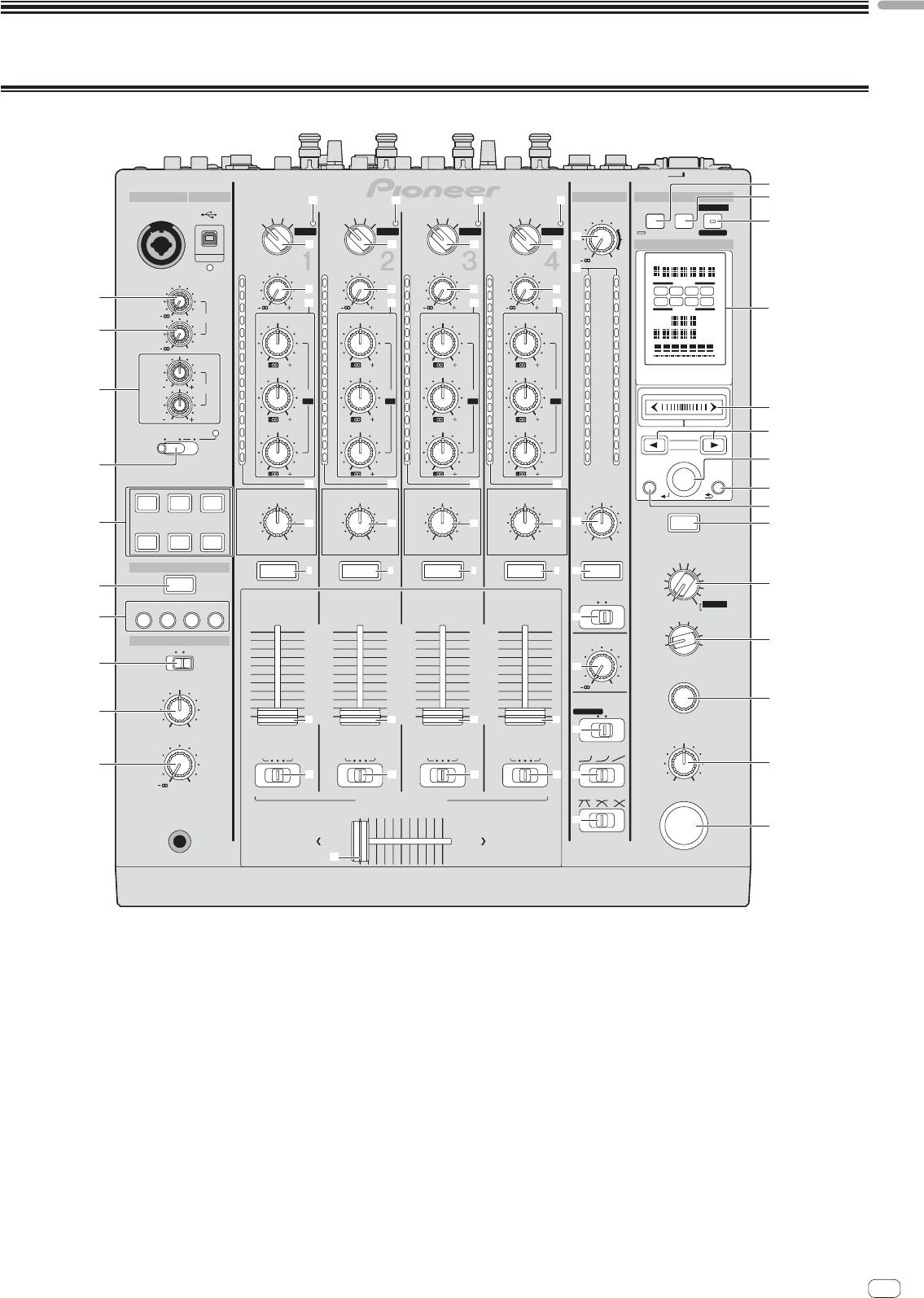
1 MIC1 LEVEL control (page 15)
9 MIXING control (page 14)
Adjusts the sound level output from the [MIC1] channel.
This adjusts the monitor volume balance of the sound of channels for which the
[CUE] button is pressed and the sound of the [MASTER] channel.
2 MIC2 LEVEL control (page 15)
Adjusts the sound level output from the [MIC2] channel.
a LEVEL control (page 14)
Adjusts the sound level output from the headphones.
3 EQ (HI, LOW) controls (page 15)
These adjust the tone quality of the [MIC1] and [MIC2] channels.
b USB audio input indicator
Lights when sound is being input from the computer to the various channels.
4 OFF, ON, TALK OVER selector switch (page 15)
Turns the microphone on/off.
c Input selector switches (page 14)
Selects the input source of each channel from the components connected to
5 SOUND COLOR FX buttons (page 16)
this unit.
These turn the SOUND COLOR FX effects on/off.
d TRIM control (page 14)
6 CUE button (page 14)
Adjusts the level of audio signals input in each channel.
Presses the [CUE] button(s) for the channel(s) you want to monitor.
e EQ/ISO (HI, MID, LOW) controls (page 14)
7 FADER START (1, 2, 3, 4) buttons (page 16)
These adjust the sound quality of the respective channels.
These turn the fader start function on/off.
f Channel Level Indicator (page 14)
8 MONO SPLIT, STEREO selector switch (page 14)
Displays the sound level of the respective channels before passing through the
Switches how the monitor sound output from the headphones is distributed.
channel faders.
En
13
