Pioneer DJM-900SRT: Connecting input terminals Connecting output terminals
Connecting input terminals Connecting output terminals: Pioneer DJM-900SRT
Table of contents
- Contents
- Before start
- Installing the software
- Installation Procedure (Windows) Installing the Serato DJ software Installation procedure (Mac OS X)
- Installation Procedure (Windows) Installation procedure (Mac OS X) 9 Log in.
- 11 Read the terms of the license agreement carefully, and if you agree, click [Agree].
- Connections Rear panel
- Connecting input terminals Connecting output terminals
- Connecting to the control panel Connecting this unit and computer
- Operation Control Panel
- Basic Operation
- Advanced Operations About PRO DJ LINK Using the QUANTIZE function
- Using the FADER START function Using the SOUND COLOR FX function Using the BEAT EFFECT function Using the LINK MONITOR function
- Operating DJ software using the MIDI function Operating the [X-PAD]
- Operating an external MIDI sequencer
- Types of effects Types of SOUND COLOR FX effects Types of BEAT EFFECT
- MIDI assignment map Category
- Category
- Changing the settings About the auto standby function About the talk over function Setting preferences About the setting utility software
- Adjusting the buffer size (when using Windows ASIO) Setting the audio data output from this unit to the computer Checking the version of the driver software Checking the latest information on the driver software
- Additional information Troubleshooting
- Block Diagram
- Acquiring the manual About trademarks and registered trademarks
- Specifications
English
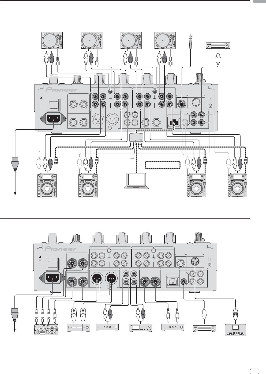
Connecting input terminals
When creating a DVS (Digital Vinyl System) combining a computer, audio interface, etc., be careful in connecting the audio interface to this unit’s input terminals and in
the settings of the input selector switches.
Also refer to the operating instructions of the DJ software and audio interface.
Analog player Analog player Analog player
Analog player
Microphones
Digital audio output device
L
R
L
R
L
R
L
R
CH 4 CH 3
CH 2
CH 1
PHONO PHONO PHONO
CD/ LINE
CD/ LINE
CD/ LINE
PHONO
CD/ LINE
RETURN
L
L
L
L
R
L
(MONO)
MIC2
MIDI OUT
OFF
POWER
ON
SIGNAL GND SIGNAL GND
R
R
R
R
MASTER1 MASTER2
REC OUT
BOOTH
DIGITAL
SEND
R
L
L
L
TRS
CH1CH2
LR
(MONO)
R
L
LINK
MASTER
OUT
IN
R
R
AC IN
1 GND
2 HOT
CH4
CH3
3 COLD
Switching hub
L
R
L
R
L
R
L
R
PRO DJ LINK
1
rekordbox
Computers
2
To power outlet
Pioneer DJ players
Pioneer DJ players
2
1 For details on PRO DJ LINK, see About PRO DJ LINK on page 15.
2 To use the fader start function with PRO DJ LINK, connect a LAN cable (page 16).
Connecting output terminals
CH 4 CH 3
CH 2
CH 1
PHONO
CD/ LINE
CD/ LINEPHONO
CD/ LINEPHONO
PHONO
CD/ LINE
RETURN
L
L
L
L
MIC2
MIDI OUT
OFF
POWER
R
L
(MONO)
ON
SIGNAL GND SIGNAL GND
R
R
R
R
MASTER1 MASTER2
REC OUT
BOOTH
DIGITAL
SEND
R
L
L
L
TRS
CH1CH2
LR
(MONO)
R
L
LINK
MASTER
OUT
IN
R
R
AC IN
CH3
1 GND
2 HOT
CH4
3 COLD
3
L
R
L
R
To power outlet
Power amplifier
2
Power amplifier
2
Cassette deck, etc.
Power amplifier
Digital audio
External effector
1
(analog input recording device)
(for booth monitor)
input device
MIDI sequencer
1 Also connect the external effector to the [RETURN] terminal (input terminal).
2 Be sure to use the [MASTER1] terminals only for a balanced output. Connection with an unbalanced input (such as RCA) using an XLR to RCA converter cable (or con-
verter adapter), etc., may lower the sound quality and/or result in noise.
For connection with an unbalanced input (such as RCA), use the [MASTER2] terminals.
3 Be careful not to accidentally insert the power cord of another unit to [MASTER1] terminal.
En
11
