Asus Motherboard: instruction
Class: Computer equipment, hardware, accessories
Type: Motherboard
Manual for Asus Motherboard
Table of contents
- Index 1. English .................................................................................1
Index
1. English .................................................................................1
2. Türkçe ................................................................................41
3.
.............................................................................
81
4. ...............................................................................121
.............................................................................161
6. Bahasa Indonesia ............................................................
201
7. Italiano
..............................................................................241
8.
한국어
..............................................................................
281
9. Polski ................................................................................321
10. Português .........................................................................361
............................................................................401
12.
..............................................................................
441
13. Srpski ...............................................................................481
14. Español ............................................................................521
15.
ไทย
...................................................................................
561
.........................................................................
601
17. ................................................................................641
18. ................................................................................681

Motherboard
installation guide
Motherboard

E4204
September 2008
Copyright © 2008 ASUSTeK COMPUTER INC. All Rights Reserved.
permission of ASUSTeK COMPUTER INC. (“ASUS”).
product is defaced or missing.

Safety information
Electrical safety
•
•
power cables for the devices are unplugged before the signal cables are
•
Before connecting or removing signal cables from the motherboard, ensure
that all power cables are unplugged.
•
Seek professional assistance before using an adpater or extension cord.
These devices could interrupt the grounding circuit.
•
•
Operation safety
•
the manuals that came with the package.
•
•
•
•
Place the product on a stable surface.
•
English
Chapter 1: Quick Start
1.1 Installing the CPU
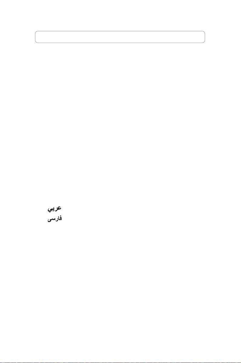
1.1.1 Intel LGA775 Socket
2. Release the load lever from the
motherboard.
retention tab and lift the load plate.
Then push the PnP cap from the
load plate window to remove
To prevent damage to the socket
pins, do not remove the PnP cap
Pick and Place Cap (PnP Cap)
4. Make sure that the gold triangle
3. Position the CPU over the socket.
is on the bottom‑left corner of the
socket.
4

English
6. Close the load plate, then push the load lever until it snaps into the retention
tab.
CPU into the socket to prevent
bending the connectors on the
socket and damaging the CPU!
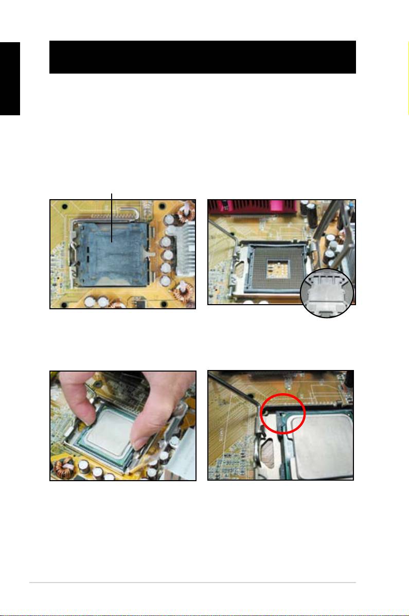
1.1.2 Intel LGA1366 Socket
Retention tab
motherboard.
A
thumb (A), then move it to the left
(B) until it is released from the
retention tab.
B
Load lever
To prevent damage to the socket
pins, do not remove the PnP cap
Load plate
the arrow to a 135º angle.
4
3
ASUS Motherboard installation guide 5
English
5. Remove the PnP cap from the CPU
6. Position the CPU over the socket,
socket.
making sure that the gold triangle
is on the bottom‑left corner of the
Gold
triangle
mark
PnP cap
CPU notch
Alignment key
socket to prevent bending the connectors on the socket and damaging the CPU!
8. Close the load plate (A), and then
push the load lever (B) until it snaps
A
into the retention tab.
B
6
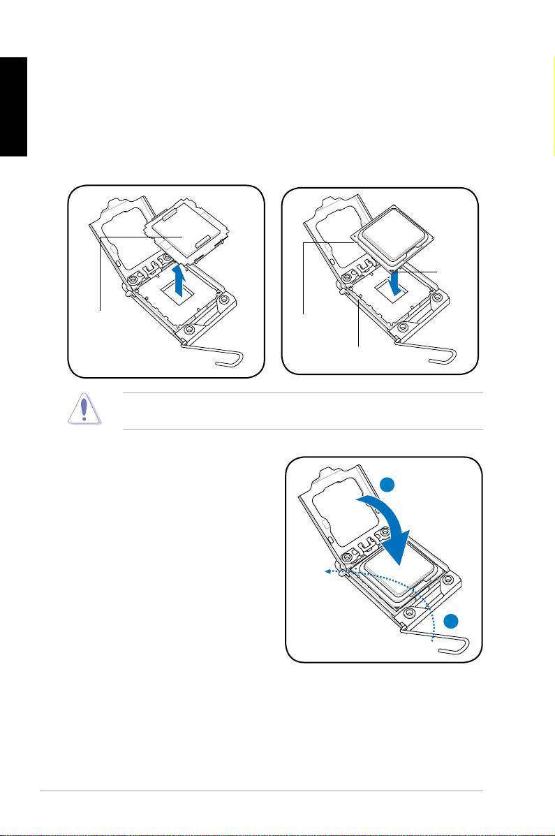
1.1.3 AMD AM2 Socket
English
motherboard.
the socket, then lift it up to a 90º
angle.
Make sure that the socket lever is lifted up to 90º angle. Otherwise, the CPU will
3. Position the CPU above the socket
such that the CPU corner with the
down the socket lever to secure the
gold triangle matches the socket
CPU. The lever clicks on the side tab
corner with a small triangle.
to indicate that it is locked.
socket to prevent bending the connectors on the socket and damaging the CPU!
ASUS Motherboard installation guide 7
English
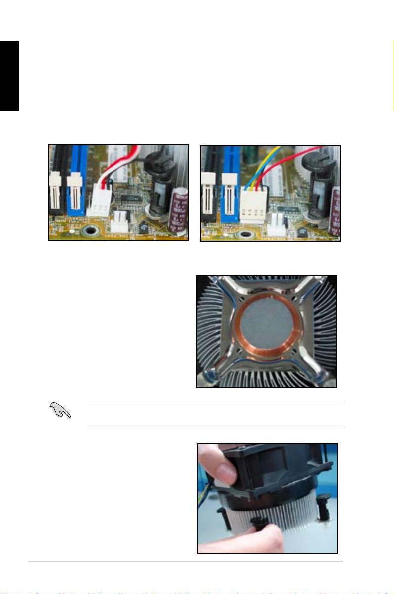
1.2 Installing the heatsink and fan
For Intel-certied heatsink:
2. Some heatsinks will come with
pre‑applied thermal paste. If so,
do not scrape it off and remove
installation. If not, before installing
thermal paste to the exposed area
of the CPU that the heatsink will be
in contact with. Make sure that it is
3. Orient each fastener with the
narrow end of the groove pointing
outward.
8
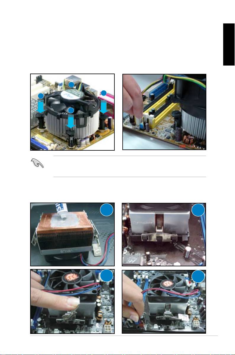
4. Push down two fasteners at a time
5. Connect the CPU fan cable to the
in a diagonal sequence to secure
corresponding connector on the
English
motherboard.
place.
B
A
A
B
directional heatsink to gain the maximum heat dissipation area.
For AMD-certied heatsink:
1
2
3
4
ASUS Motherboard installation guide 9
English
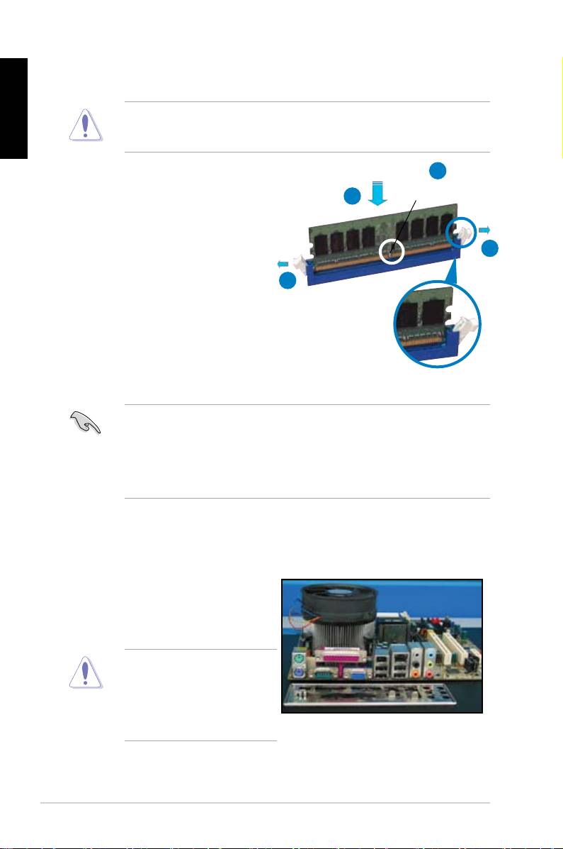
1.3 Installing a DIMM
motherboard and the components.
2
DDR2 DIMM notch
3
1. Press the retaining clips outward
1
matches the break on the socket.
1
socket until the retaining clips
Unlocked retaining clip
motherboard package.
1.4 Installing the motherboard
1. I/O ports differ with motherboards.
Use and install the rear I/O shield
that comes with the motherboard
Some sharp edges and points
puncture resistant gloves before
motherboard and I/O shield
installation.
10
2. Install the standoffs to the matched
screw holes on the metal plate.
damage the I/O ports. Be cautious
English
when installing the I/O shield.
4. Position the I/O side of the
motherboard toward the rear of the
After all the screws have been
chassis and place the motherboard
inserted, drive the screws until
into the chassis.
of the chassis before installing the motherboard. For some chassis models,
ASUS Motherboard installation guide 11
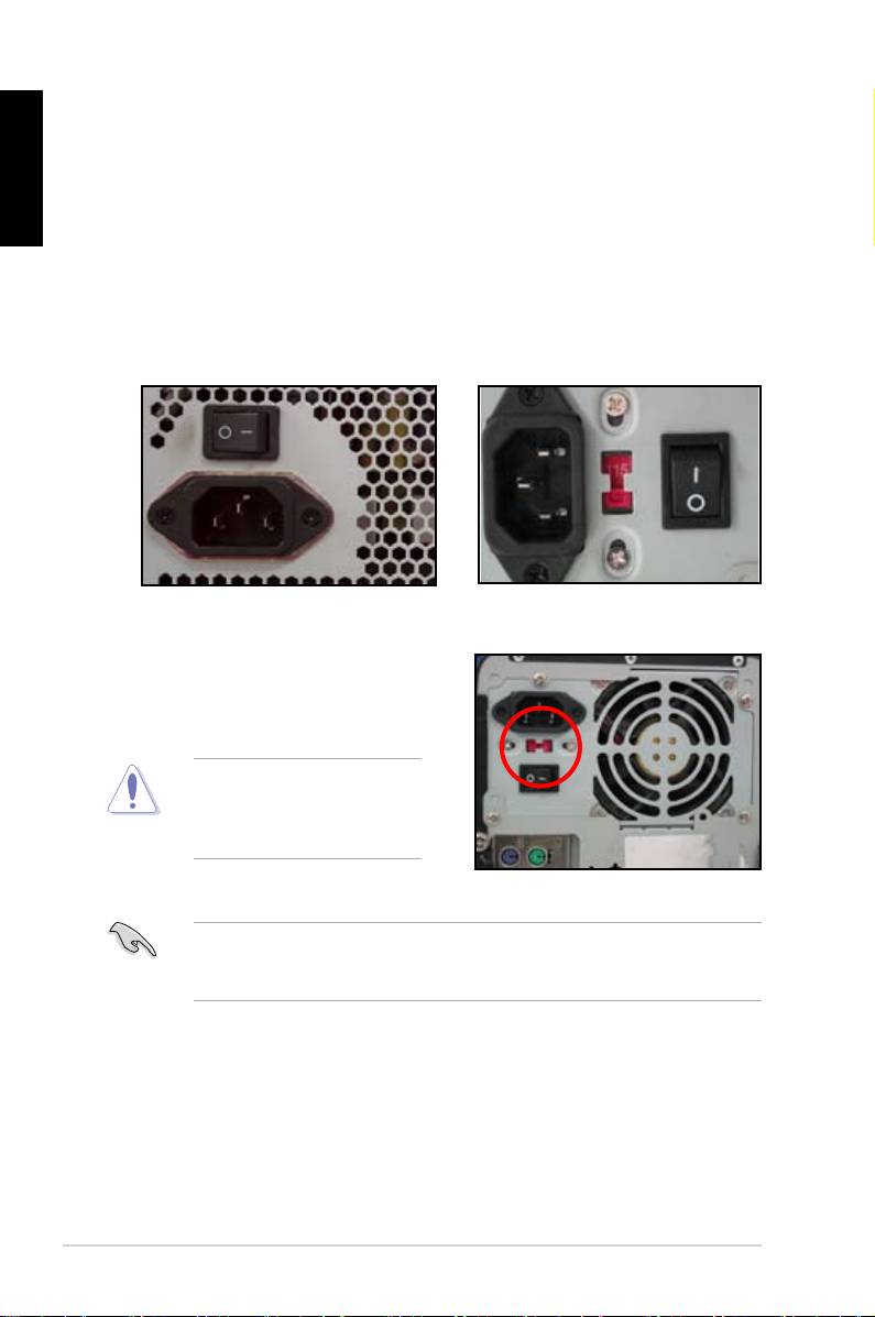
1.5 Installing the power supply unit
English
Power Factor Correction (PFC) and the other with passive PFC.
Power supply with active PFC:
Power supply with passive PFC:
Passive PFC requires user to
the AC input voltage.
voltage.
area.
12
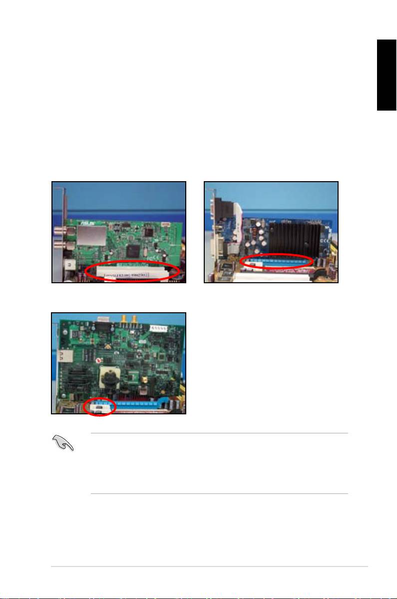
1.6 Installing an expansion card
English
wish to install an expansion card.
3. Screw to secure the card on the slot.
4. Repeat the previous steps to install another expansion card.
PCI card PCIE x16 card
PCIE x1 card
after installing the expansion card.
• Refer to the motherboard user guide for the instructions of the expansion
card signal cable connection.
ASUS Motherboard installation guide 13
1.7 Installing disk drives
English
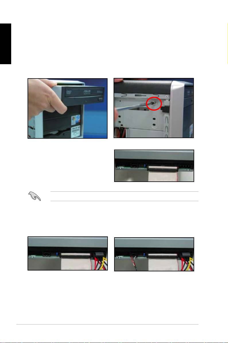
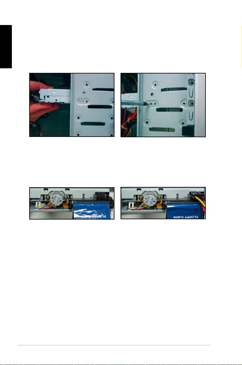
1.7.1 PATA optical disk drive
2. Align with the screw holes and
slide the optical disk drive into the
secure the disk drive with screws.
the optical drive. The red stripe on
should match the dimple marking
Pin1 on the optical drive.
4. Connect the 4‑pin power cable to
5. Attach the audio cable to the
the optical drive.
connector on the optical drive.
14
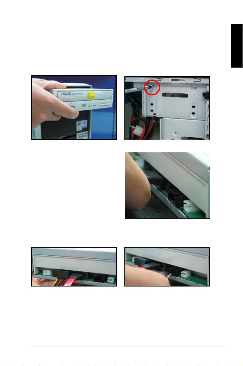
1.7.2 SATA optical disk drive
2. Align with the screw holes and
English
slide the optical disk drive into the
secure the disk drive with screws.
3. Orient and plug the SATA cable into
the optical drive. SATA cables are
cable into the connector.
4. Connect the SATA power cable to
5. Attach the audio cable to the
the the optical drive.
connector on the optical drive.
ASUS Motherboard installation guide 15
English
1.7.3 Floppy disk drive
2. Align with the screw holes and
secure the disk drive with screws.
the connector at the back of the
red stripe on the cable is the pin1
end and should match pin1 on the
16
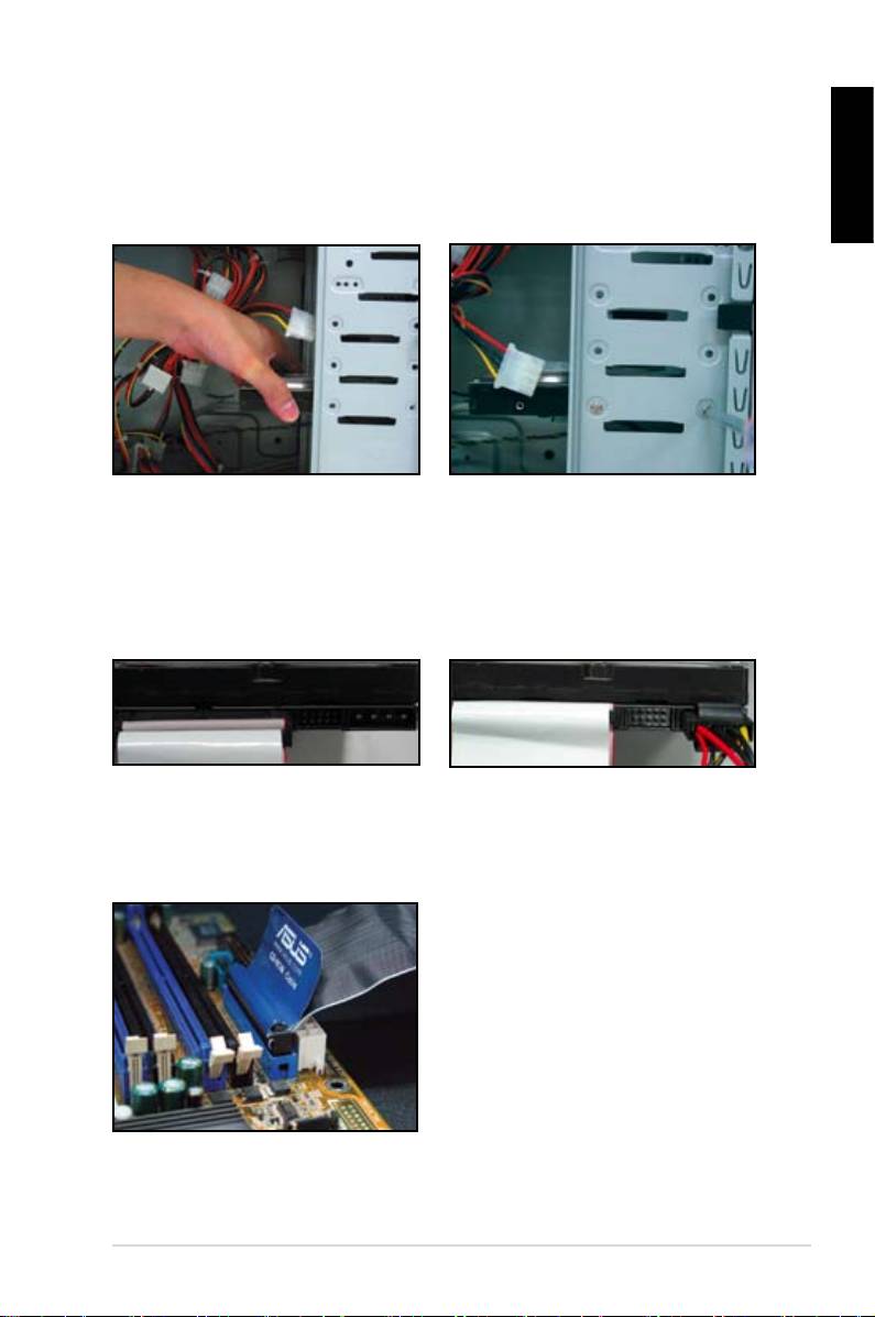
1.7.4 PATA hard disk drive
1. Insert the PATA hard disk drive into
2. Align with the screw holes and
English
secure the disk drive with screws.
3. Orient and connect the signal cable
4. Connect the 4‑pin power cable to
to the hard disk drive. The red stripe
the connector at the back of the
on the cable is the pin1 end. Match
hard disk drive.
force the cable into the connector.
5. Attach the other end of the signal
cable to the corresponding slot on
the motherboard.
ASUS Motherboard installation guide 17
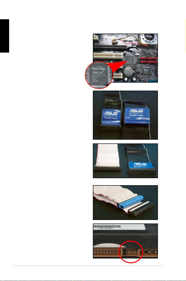
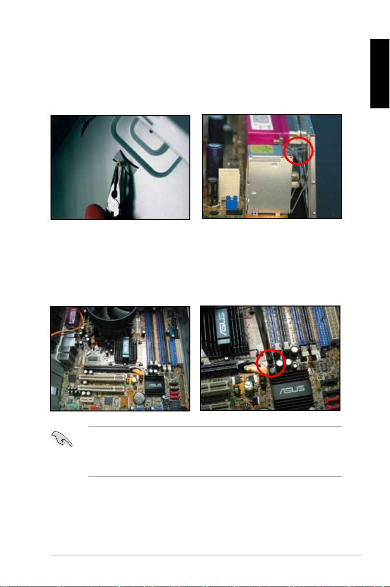
Notes for installing PATA hard disk drive
English
have to install the controller driver
• The cables are designed with pull
drives based on the cable labels.
To prevent damaging the pins, pull
the cable tabs to disconnect the
cable.
disk drives, the newer 80‑wire
(right) and the older 40‑wire (left)
cables. For ATA66/100/133 disk
offer a better performance. The
optical drives.
• The cable connector is color‑
coded. The blue one is for the host
drive.
different position, one in master
18
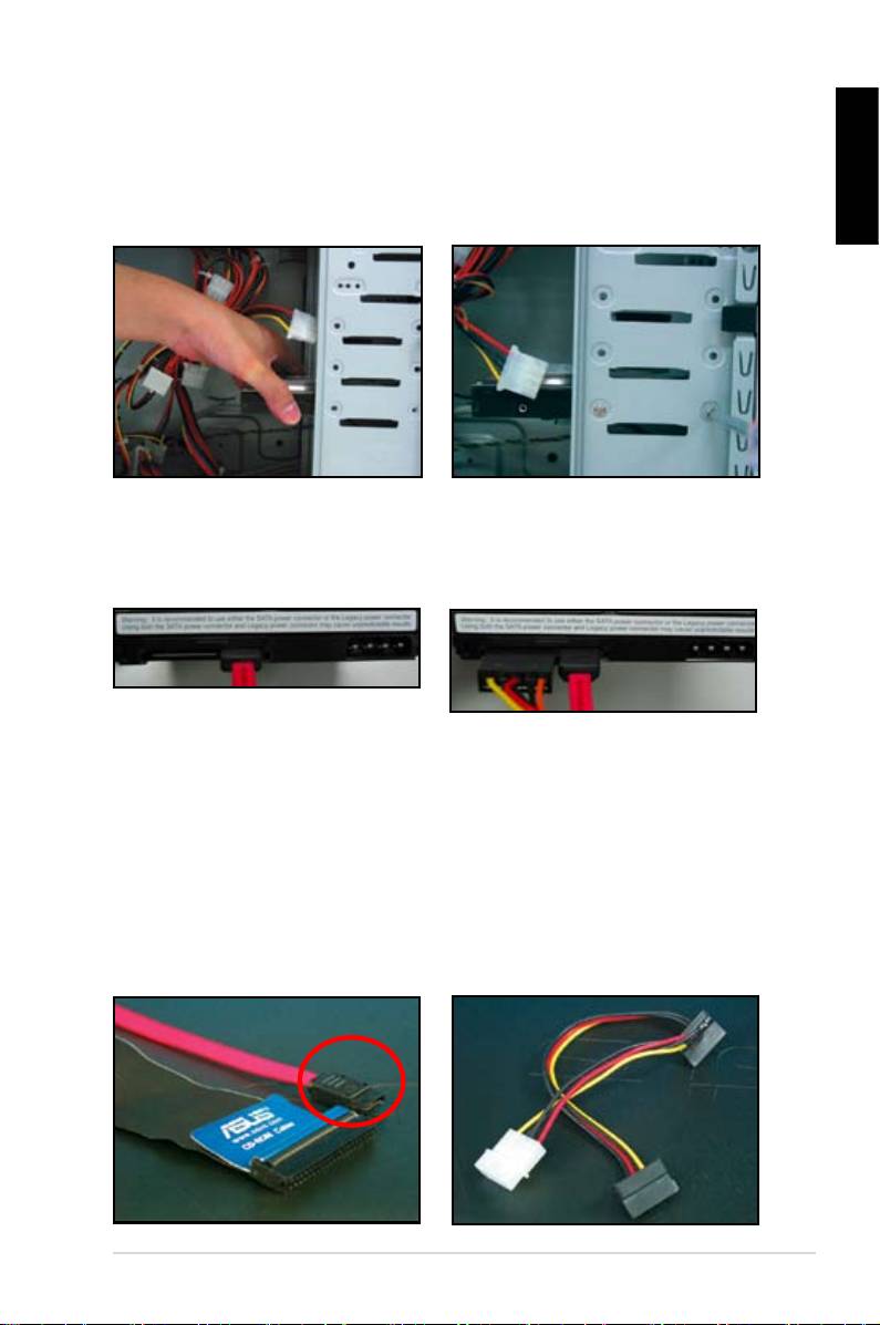
1.7.5 SATA hard disk drive
1. Insert the SATA hard disk drive into
2. Align with the screw holes and
English
secure the disk drive with screws.
3. Orient and connect the SATA cable
4. Connect the SATA power cable to
to the hard disk drive. The cable can
the connector at the back of the
hard disk drive.
Notes for installing SATA hard disk drive
• Serial ATA (SATA) interface
• The SATA power cable connector
provides higher data transmission
is different from the traditional
speed, and better voltage tolerance.
4‑pin power connector. ASUS
The narrow design of the SATA
motherboard bundles power adapter
cable also solves cabling issues
chassis.
new connector.
ASUS Motherboard installation guide 19
