Asus V6-P5G31E: Selecting the voltage Removing the side cover and front panel assembly Installing a CPU Installing an Intel CPU
Selecting the voltage Removing the side cover and front panel assembly Installing a CPU Installing an Intel CPU: Asus V6-P5G31E
Table of contents
- Rear panel features Internal components
- Selecting the voltage Removing the side cover and front panel assembly Installing a CPU Installing an Intel CPU
- Installing an AMD CPU Installing the CPU fan and heatsink assembly Installing an Intel CPU heatsink and fan
- Installing an AMD CPU heatsink and fan Installing a DIMM
- Installing an expansion card Installing storage drives Optical drive Floppy disk drive
- Hard disk drive Reinstalling the front panel assembly and side cover
English
4
Installation manual
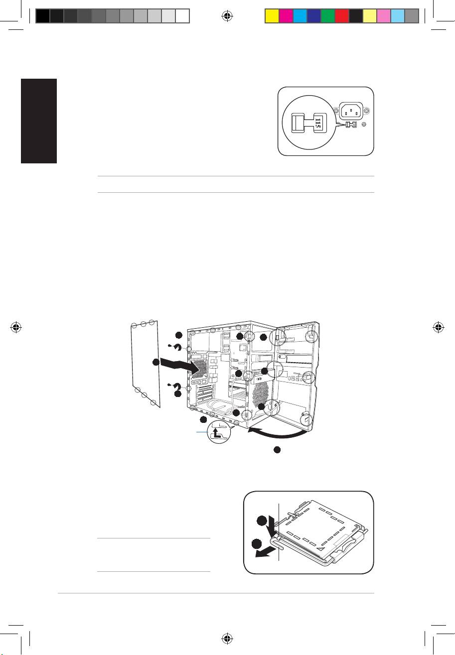
Selecting the voltage
The system’s power supply unit has a 115 V/230 V voltage
selector switch located beside the power connector. Use
this switch to select the appropriate system input voltage
according to the voltage supply in your area.
If the voltage supply in your area is 100-127 V, set the switch
to 115 V.
If the voltage supply in your area is 200-240 V, set the switch
to 230 V.
NOTE: Refer to the system User Guide for the exact location of the voltage selector.
Removing the side cover and front panel assembly
1. Remove the cover screws on the rear panel.
2. Pull the side cover toward the rear panel until its hooks disengage from the chassis tab
holes. Set the side cover aside.
3. Locate the front panel assembly hooks, then lift them until they disengage from the
chassis.
4. Swing the front panel assembly to the right, until the hinge-like tabs on the right side of
the assembly are exposed.
5. Remove the front panel assembly, then set aside.
1
3
4
2
4
3
1
4
3
2
Chassis tab holes
4
Installing a CPU
Installing an Intel CPU
1. Locate the CPU socket on the motherboard.
Retention tab
2. Press the load lever with your thumb (2A),
then move it to the left (2B) until it is released
2A
from the retention tab.
2B
CAUTION! To prevent damage to the
socket pins, do not remove the PnP cap
unless you are installing a CPU.
Load lever
V7-P5G43 QSG.indb 4 9/1/09 4:59:46 PM
