Indesit KJ1G1: Installation
Installation: Indesit KJ1G1
15
All instruction on the following pages must be carried out
by a competent person (corgi registered) in compliance
with gas safety (installation and use) regulation 1984.
Important: disconnect the cooker from the electrycity
and gas supply when any adjustment, etc.
Positioning your appliance
Important:
this appliance may be installed and used only
in permanently ventilated rooms in compliance with current
directives. The following precautions should be taken:
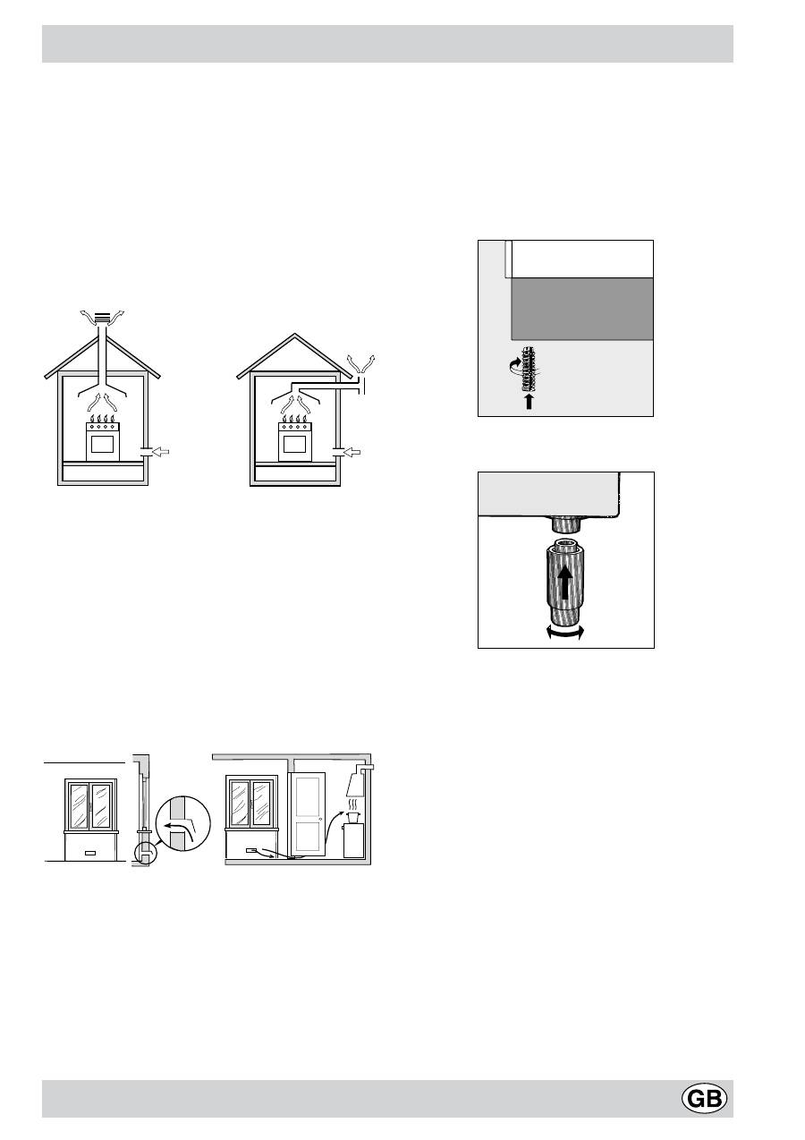
a)
The room must be provided with an external exhaust
system obtained with a hood or with an electric
ventilator that goes on automatically each time the unit
is switched on.
In the case of chimneys or flues
Directly to the
with branches (for cookers)
exterior
b)
The room must be provided with a system for air inflow
which is necessary for a regular combustion. The air
flow necessary for the combustion should be at least 2
m
3
/h for kW of installed power. The system may be
realized by drawing the air directly from outside the
building through a pipe that has at least a 100 cm
2
useable section and which must not be accidently
obstructed (Fig. A). And further it may be realized
indirectly from other adjacent rooms which are provided
with a ventilation pipe for the expulsion of the fumes to
the outside of the building as foresaid, and which must
not be part of the building in common use or rooms
with risk of fire, or bedrooms (Fig. B).
Detail A
Adjacent
Room to
room
be ventilated
Fig. A
Fig. B
Examples of ventilation openings
Increased opening between
for the comburent air
the door and and floor
c)
During prolonged use of the appliance you may
consider it necessary to open a window to the outside
to improve ventilation.
d)
The liquefied petroleum gases, which are heavier than
air, stagnate towards the ground. Therefore, the rooms
containing LPG cans must have openings towards the
outside in order to allow the venting from the ground of
eventual gas leak. Thus, the LPG cans must not be
installed or settled in rooms that are below the ground
level, (cellar, etc.) whether the cans are empty or
partially full. It is advisable to keep in the room only
the can which is being used, and it must be placed
away from direct heat sources (ovens, fireplaces,
stoves, etc.) that could make the can reach
temperatures higher than 50°C.
Levelling your appliance
(only on a few models)
Your cooker is supplied with feet for levelling the appliance.
If necessary, these feet can be screwed into the housings
in the corners of the cooker base.
Mounting the legs
(only on a few models)
Press-fit legs are supplied which fit under the base of your
cooker.
Installation of the cooker
The appliance can be installed next to furniture units which
are no taller than the top of the cooker hob. The wall in
direct contact with the back panel of the cooker must be
made of non-flammable material. During operation the
back panel of the cooker could reach a temperature of
50°C above room temperature. For proper installation of
the cooker, the following precautions must be taken:
a)
The appliance can be placed in a kitchen, dining room
or bedsit, but not in a bathroom.
b)
All furniture around the appliance must be placed at
least 200 mm from the top of the cooker, should the
surface of the appliance be higher than the worktop of
this furniture. Curtains should not be placed behind
the cooker or less than 200 mm away from the sides
of the appliance.
c)
Any hoods must be installed according to the require-
ments in the installation manual for the hoods them-
selves.
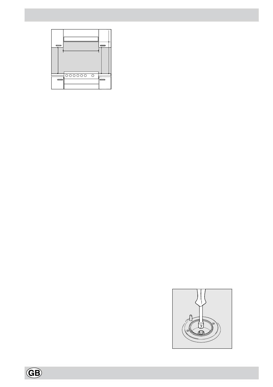
d)
If the cooker is installed beneath a wall cabinet, the
latter must be situated at a minimum of 420 mm above
the hob. The minimum distance between the worktop
and kitchen units made of combustible material is 700
mm.
e)
The wall in direct contact with the back panel of the
cooker must be made of non-flammable materials.
A
Installation
16
Connecting the gas
The appliance should be connected to the mains or to a
gas cylinder in compliance with current directives. Before
making the connection, check that the cooker is regulated
for the gas supply you are using. If not, follow the
instructions indicated in the paragraph “Adapting to
different types of gas”. On some models the gas supply
can be connected on the left or on the right, as necessary;
to change the connection, reverse the position of the hose
holder with that of the cap and replace replace the gasket
(supplied with the appliance). When using liquid gas from
a cylinder, install a pressure regulator which complies with
current directive.
Important:
check that the supply pressure complies with
the values indicated in table 1 “Characteristics of the
burners and nozzles” since this will ensure safe operation,
correct consumption and ensure a longer life to your
appliance.
Connection with hose
Make the connection using a gas hose complying with
the the characteristics provided in current directive. The
internal diameter of the pipe used is as follows:
- 8mm for liquid gas;
- 13mm for methane gas.
When installing the hose, remember to take the following
precautions:
•
No part of the hose should touch parts whose tempe-
rature exceeds 50°C;
•
The length of the hose should be less than 1500 mm;
•
The hose should not be subject to twisting or pulling,
and should not have bends or kinks.
•
The hose should not touch objects with sharp edges,
any moving parts, and it should not be crushed;
•
The full length of the hose should be easy to inspect in
order to check its condition;
Check that the hose fits firmly into place at the two ends
and fix it with clamps complying to current directive.If any
of the above recommendations can not be adopted, flexible
metal pipes should be used.
Should the cooker be installed according to the conditions
of Class 2, subdivision 1, only a flexible metal pipe which
is in compliance with current safety standards should be
used to make the connection to the gas mains.
Connecting a flexible jointless stainless steel pipe
to a threaded attachment
Remove the hose holder fitted on the appliance. The gas
supply pipe fitting is a threaded 1/2 gas cylindrical male
attachment. Only pipes and gaskets complying with current
directives. The full length of the pipe must not exceed 2000
mm.
Tight control
Important:
when installation has been completed, check
the pipe fitting for leaks with a soapy solution. Never use a
flame. Once the connection has been made, ensure that
the flexible metal tube does not touch any moving parts
and is not crushed.
Connecting the supply cable to the mains
Install a normalised plug corresponding to the load
indicated on the data plate. When connecting the cable
directly to the mains, install an omnipolar circuit-breaker
with a minimum contact opening of 3 mm between the
appliance and the mains. The omnipolar circuit breaker
should be sized according to the load and should comply
with current regulations (the earth wire should not be
interrupted by the circuit breaker).
The supply cable should be positioned so that it does not
reach a temperature of more than 50°C with respect to
the room temperature, along its length. Before making the
connection, check that:
•
the limiter valve and the home system can support the
appliance load (see data plate);
•
the mains is properly earthed in compliance with
current directives and regulations;
•
there is easy access to the socket and omnipolar circuit
breaker, once the hob has been installed.
N.B:
never use reducers, adaptors or shunts since they
can cause heating or burning.
The plug and socket must
be easily accessible.
Adapting the cooker to different types of gas
In order to adapt the cooker to a different type of gas with
respect to the gas for which it was produced (indicated on
the label attached to the lid), follow these steps:
a)
replace the hose holder mounted on the appliance with
that supplied in the bag of “cooker accessories”.
Important:
the hose holder for liquid gas is marked 8, the
hose holder for methane gas is marked 13. Always fit the
sealing gasket.
b)
Replacing the burner nozzles on the hob:
•
remove the grids and slide the burners from their
housings;
•
unscrew the nozzles using a 7 mm socket spanner,
and replace them with nozzles for the new type of gas
(see table 1 “Burner and nozzle characteristics”).
•
replace all the components by repeating the steps in
reverse order.
c)
Minimum regulation of the hob burners:
•
turn the tap to minimum;
HOOD
420
Min.
min.
650
mm. with hood
min.
700
mm. without hood
mm.
600
Min.
mm.
420
Min.
mm.
Оглавление
- Avvertenze
- Istruzioni per l’installazione
- Caratteristiche dei bruciatori ed ugelli
- Caratteristiche tecniche
- La cucina con forno elettrico
- •
- Consigli pratici per la cottura
- Manutenzione ordinaria e pulizia della cucina
- Consigli pratici per la cottura
- Important safety warnings
- Installation
- Burner and nozzle characteristics
- Technical Specifications
- The cooker with electric oven
- •
- Cooking advice
- Cooker routine maintenance and cleaning
- Cooking advice
- Áåçîïàñíîñòü õîðîøàÿ ïðèâû÷êà
- Óñòàíîâêà
- Õàðàêòåðèñòèêè ãîðå ë îê è æ èê ë åðîâ
- Òåõíè÷åñêèå õàðàêòåðèñòèêè
- Ï ë èòà ñ ýë åêòðè÷åñêî é äó õîâêî é (îïèñàíèå )
- •
- Ïðàêòè÷åñêèå ñîâåòû
- Î á ñ ëóæ è âàí èå è ó õ î ä
- Cooking advice
- Indesit Company
