Indesit HIM 531 EK.A IX: инструкция
Раздел: Кухонная техника
Тип: Духовка
Инструкция к Духовке Indesit HIM 531 EK.A IX
OVEN
HIM 50 EK.A
HIM 50 EK.A IX
Contents
Installation, 2-4
Positioning
Electrical connections
Data plate
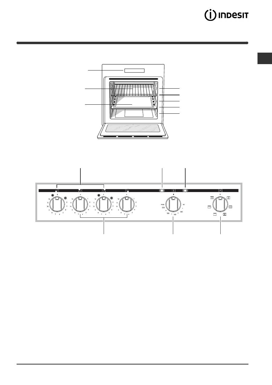
Description of the appliance, 5
Overall view
Control panel
Start-up and use, 6
Starting the oven
Using the cooking timer
Cooking modes, 7-8
Cooking modes
Practical cooking advice
Cooking advice table
Hob, 9
Type of hob
Switching on the glass ceramic hob
Practical advice on using the glass ceramic hob
Precautions and tips, 10
General safety
Disposal
Respecting and conserving the environment
Maintenance and care, 11
Switching the appliance off
Cleaning the appliance
Cleaning the oven door
Replacing the light bulb
Assistance
Operating Instructions
GB
Nederlands, 23
English,1
Deutsch, 34
ÅëëçíéêÜ
,
45
Français, 12
FR
GB
NL
DE
GR
Русский
, 56
RS
2
GB
!
Before placing your new appliance into operation
please read these operating instructions carefully.
They contain important information for safe use, for
installation and for care of the appliance.
!
Please keep these operating instructions for future
reference. Pass them on to possible new owners of
the appliance.
Positioning
!
Keep packaging material out of the reach of
children.
It can become a choking or suffocation
hazard (
see Precautions and tips
).
!
The appliance must be installed by a qualified
person in compliance with the instructions provided.
Incorrect installation may cause harm to persons,
animals or may damage property.
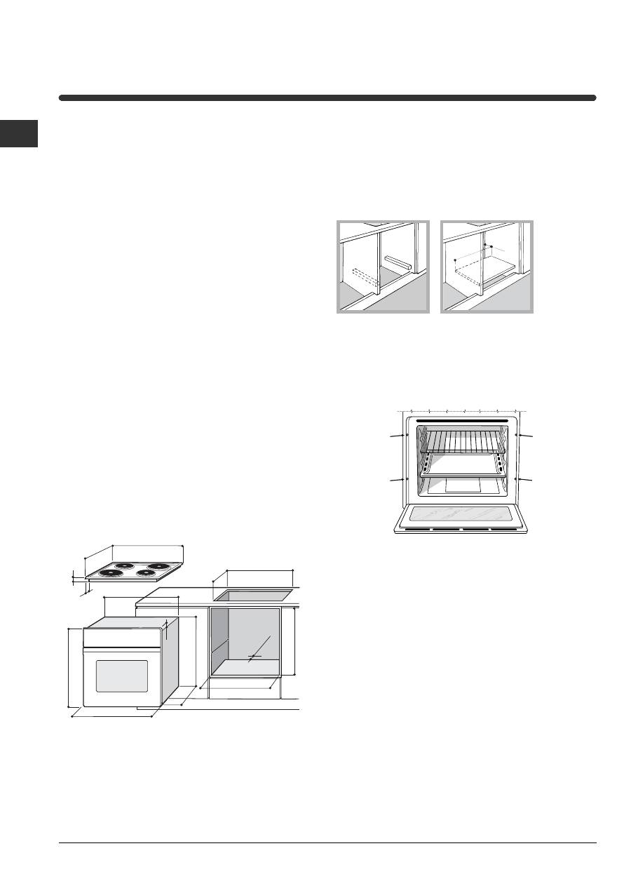
Fitting the appliance
Use the appropriate cabinet to ensure that the
appliance functions properly.
• The panels adjacent to the oven must be made of
heat-resistant material.
• Cabinets with a veneer exterior must be assembled
with glues which can withstand temperatures of up
to 100°C.
• To install the oven
under the counter
(
see
diagram
) and in a
kitchen unit
, the cabinet must
have the following dimensions:
!
The appliance must not come into contact with
electrical parts once it has been installed.
The consumption indications on the data plate have
been calculated for this type of installation.
Ventilation
To ensure good ventilation, the back panel of the
cabinet must be removed. It is advisable to install the
oven so that it rests on two strips of wood, or on a
completely flat surface with an opening of at least 45 x
560 mm (
see diagrams
).
Centring and fastening
Secure the appliance to the cabinet by opening the
oven door and putting 4 screws into the 4 holes of
the outer frame.
!
All parts which ensure the safe operation of the
appliance must not be removable without the aid of a
tool.
595
558
min
45
min
575-585
min
560
+4 -0
480
+4 -0
547 min
555
580
500
39
15
595
23
572
543
54
3
545
560 mm.
45 mm.
Installation
3
GB
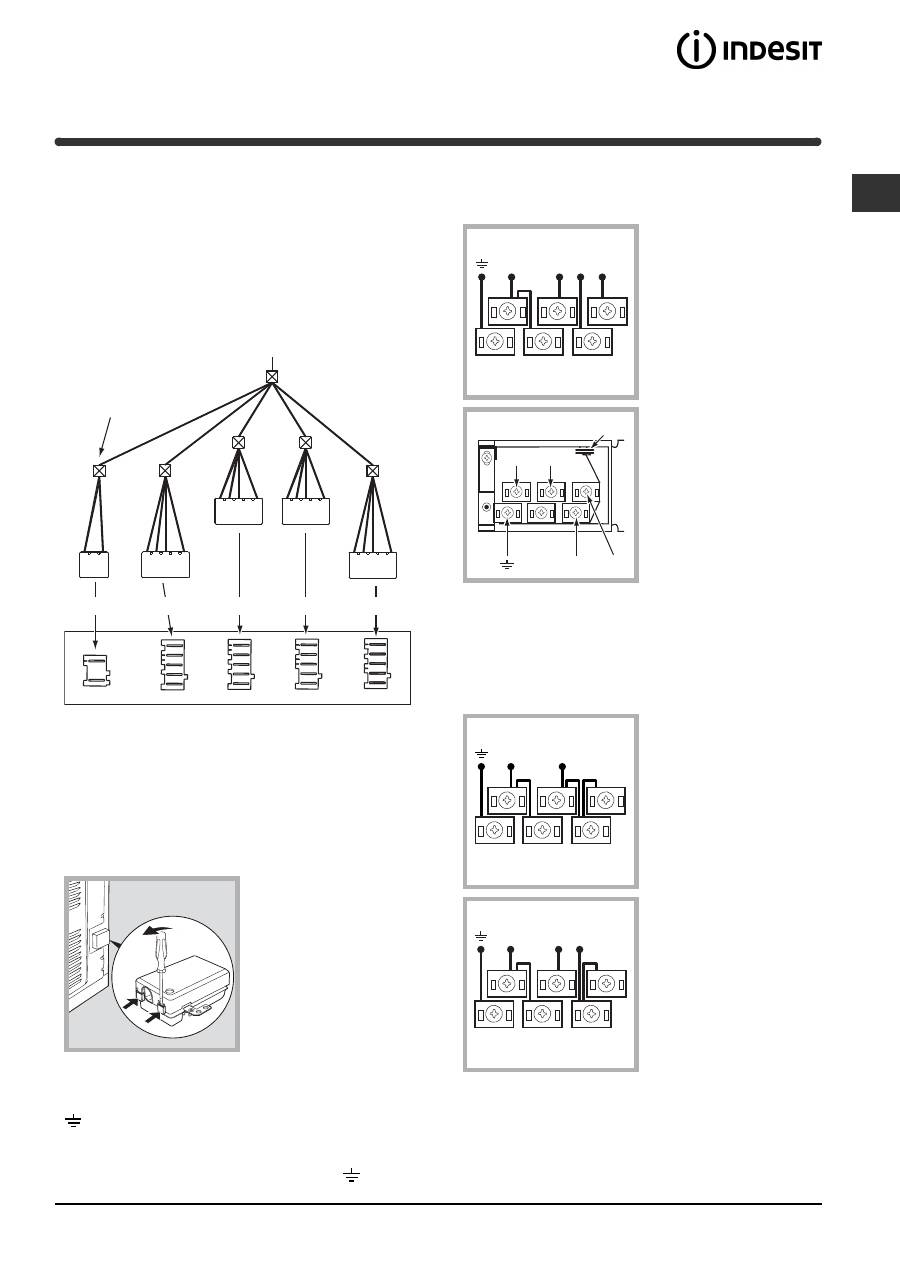
Electrical connections
The cooker must be connected to the mains
electricity supply. It is designed to operate with
alternating current at the voltage and frequency
indicated on the data plate (
see the following page
).
The hob is connected to the cooker using a special
connector.
BUILT-IN HOB
BUILT-IN COOKER
WHITE
RED
YELLOW
BLUE
GREEN
Only on
certain models
Replace the metal protection after performing all the
necessary hob connections. If the hob is removed
from its position, the red cap which was originally
protecting the red connector must be replaced.
Fitting the power supply cable
1. Open the terminal
board by inserting a
screwdriver into the
side tabs of the cover.
Use the screwdriver as
a lever by pushing it
down to open the cover
(
see diagram
).
2. Install the power supply cable by loosening the
cable clamp screw and the wire contact screws L-N-
. Connect the wires to the corresponding
terminals: the Blue wire to the terminal marked (N),
the Brown wire to the terminal marked (L) and the
Yellow Green wire to the terminal marked
.
The terminal board is designed for a 400 V three-
phase connection (
see diagrams below
).
400V 3N~H05RR-F
5x2.5 CEI-UNEL 35363
If the electrical system has other characteristics (
see
diagrams below
), carry out the electrical connection
using the connection supports provided in the box
P.
230V ~H05RR-F 3x4
CEI-UNEL 35363
400V 2N~H05RR-F 4x4
CEI-UNEL 35363
3. Secure the power supply cable by fastening the
clamp screw.
4. Close the cover of the terminal board.
N
L1
L3
L2
1
3
2
4
5
N
L2
L1
L3
P
N
L
1
3
2
4
5
N
L1 L2
1
3
2
4
5
4
GB
Connecting the supply cable to the mains
Install a standardised plug corresponding to the load
indicated on the data plate (
see side
).
The appliance must be directly connected to the
mains using an omnipolar circuit-breaker with a
minimum contact opening of 3 mm installed between
the appliance and the mains, suitable for the load
indicated and complying with current electrical
regulations (the earthing wire must not be interrupted
by the circuit-breaker). The supply cable must not
come into contact with surfaces with temperatures
higher than 50°C.
!
The installer must ensure that the correct electrical
connection has been made and that it is compliant
with safety regulations.
Before connecting to the power supply, make sure that:
• The appliance is earthed and the plug is compliant
with the law.
• The socket can withstand the maximum power of
the appliance, which is indicated on the data plate
(
see below
).
• The voltage must be in the range between the
values indicated on the data plate (
see below
).
• The socket is compatible with the plug of the
appliance. If the socket is incompatible with the
plug, ask an authorised technician to replace it. Do
not use extension cords or multiple sockets.
!
Once the appliance has been installed, the power
supply cable and the electrical socket must be easily
accessible.
!
The cable must not be bent or compressed.
!
The cable must be checked regularly and replaced
by authorised technicians only (
see Assistance
).
!
The manufacturer declines any liability should
these safety measures not be observed.
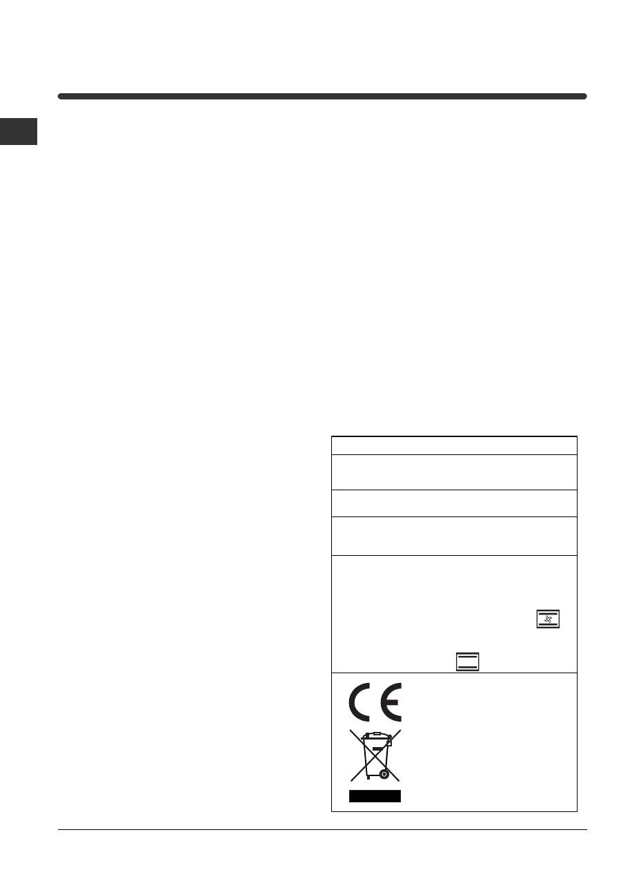
DATA PLATE
Dimensions
width 43.5 cm
height 32 cm
depth 40 cm
Volume
lt. 56
Electrical
connections
voltage: 230V/400V~ 3N 50/60Hz
maximum power absorbed 9450W
ENERGY LABEL
Directive 2002/40/EC on the label
of electric ovens.
Standard EN 50304
Energy consumption for Forced
convection heating mode:
Multi-cooking
Declared energy consumption for
Natural convection Class heating
mode: Convection
This appliance conforms to the
following European Economic
Community directives:
- 2006/95/EEC of 12/12/06 (Low
Voltage) and subsequent
amendments;
- 2004/108/EEC of 15/12/04
(Electromagnetic Compatibility) and
subsequent amendments;
- 93/68/EEC of 22/07/93 and
subsequent amendments.
- 2002/96/EC and subsequent
amendments.
5
GB
Description of the appliance
Overall view
Control panel
Control panel
GRILL
DRIPPING PAN
GUIDES
for the
sliding racks
position 5
position 4
position 3
position 2
position 1
SELECTOR
Knob
HOTPLATES
indicator light
THERMOSTAT
indicator light
THERMOSTAT
Knob
HOTPLATES
knob
EXTENDABLE HOTPLATES
knob
Оглавление
- Installation
- Description of theappliance
- Start-up and use
- Cooking modes
- Hob
- Precautions and tips
- Maintenance and care
- Mode d’emploi
- Installation
- Description del’appareil
- Mise en marche etutilisation
- Programmes
- Table de cuisson
- Précautions et conseils
- Nettoyage et entretien
- Gebruiksaanwijzing
- Het installeren
- Beschrijving van hetapparaat
- Starten en gebruik
- Programma’s
- Kookplaat
- Voorzorgsmaatregelen enadvies
- Onderhoud en verzorging
- Bedienungsanleitung
- Installation
- Beschreibung desGerätes
- Inbetriebsetzung undGebrauch
- Programme
- Kochfeld
- Vorsichtsmaßregeln undHinweise
- Reinigung und Pflege
- Ïäçãßåò ÷ñÞóçò
- ÅãêáôÜóôáóç
- ÐåñéãñáöÞ ôçò óõóêåõÞò
- Åêêßíçóç êáé ÷ñÞóç
- ÐñïãñÜììáôá
- Åðßðåäï øçóßìáôïò
- ÐñïöõëÜîåéò êáé óõìâïõëÝò
- ÓõíôÞñçóç êáé öñïíôßäá
- Руководство поэксплуатации
- Монтаж
- Описание изделия
- Включение и эксплуатация
- Программы
- Варочная панель,
- Предосторожностии рекомендации
- Техническоеобслуживание и уход
